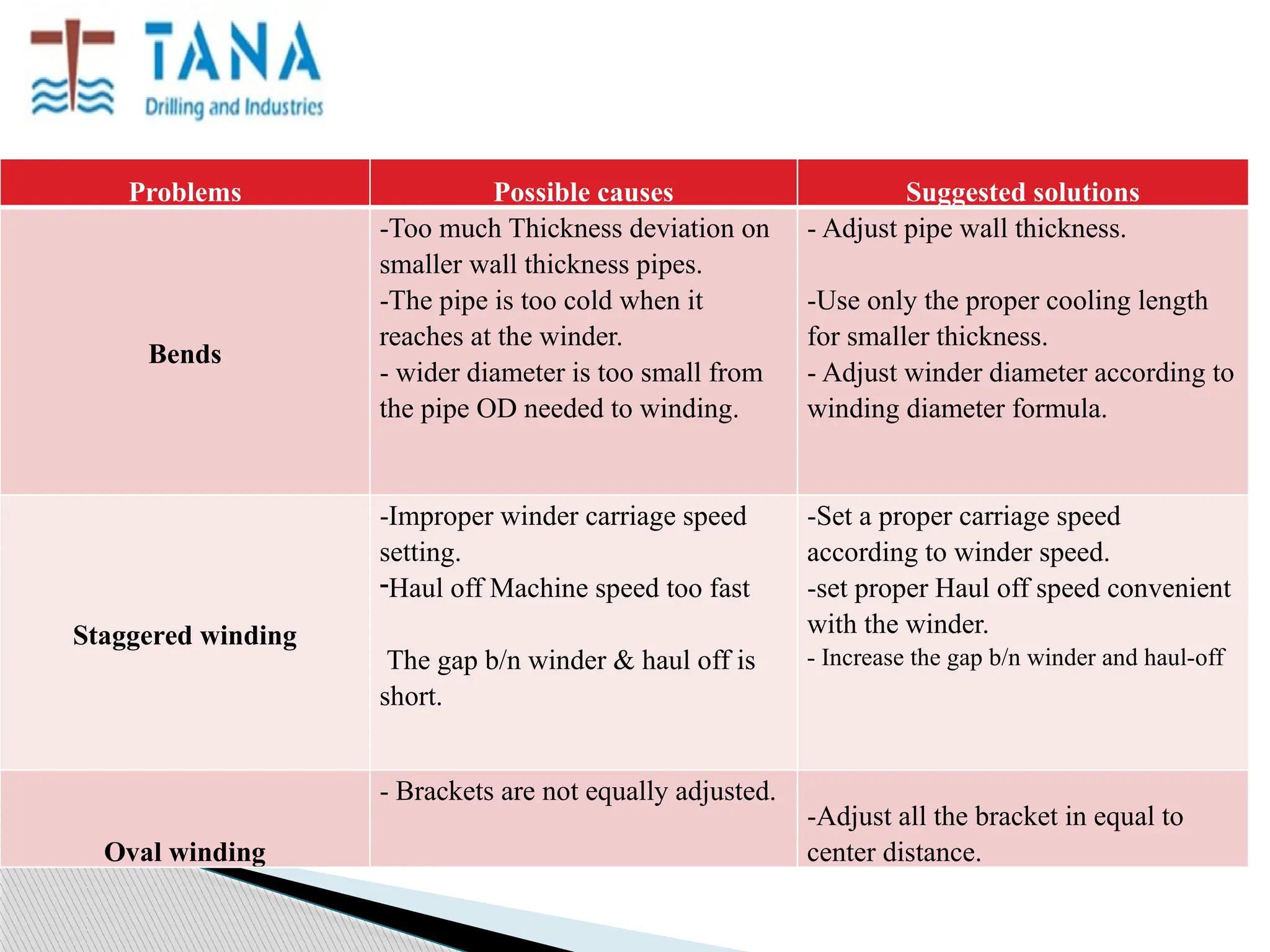
PIPE EXTRUSION
TROUBLESHOOTING
PREPARED BY:
ANAOL ASHINE
QUALITY COORDINATOR
In this training we will focus on PE pipes extrusion machine problems &
troubleshooting. So after this training you will understand how to solve and
troubleshooting PE extruder Machine.
 Before dealing with specific extrusion problems, there are some issues that should be
addressed first. There are some important prerequisites to an efficient problem solving
process.
these are:
 Good instrumentation with data acquisition system (DAS)
 Good understanding of the extrusion process
 Collect and analyze historical data
 information
 Practice critical and independent thinking
 Document the troubleshooting process and develop a database
 Team building
IMPORTANT REQUIREMENTS
GOOD INSTRUMENTATION
 The extrusion process is to a large extent a black box process. In other
words, it is not possible to visually observe what goes on inside the
extruder.
 We can see material going into the extruder and material coming out of the
extrusion die. However, what happens between the feed opening and the
die exit cannot be seen on normal extruders because the process is
obscured by the extruder barrel.
CORPORATE TRAINING A
EXTRUSION
Continuous Process
In principle, the plastic raw material is plasticized by means of a screw
plasticization unit and the molten material is continuously pumped out
through a standard orifice (die) in order to take the shape and then the
shape is set by cooling/sizing system.
Example:Film,Pipe,Tube, Profile, Monofilament, Box Strapping etc.
MAIN TYPES OF PROBLEMS
The number of extrusion problems that can occur is nearly infinite. In
this training we will discuss on the following problems.
 Output problems
 Appearance problems
 Functional product properties
 High melt temperature
 High motor load
 Wear of screw and/or barrel
These problems can be tensile strength, cracking, etc. basically, any undesirable property that
makes the product unable to perform its intended function. It may be hard to list all the cases that
Can make a part nonfunctional.
This can be related to mechanical properties, electrical Properties , optical properties, etc. An
example of a functional product problem is environmental stress-cracking, ESC. In this problem
fracture occurs when the plastic product is under stress and exposed to a chemical that reduces
the
Crack resistance of the plastic. For instance, detergent can cause ESC in HDPE
FUNCTIONAL PRODUCT PROBLEMS
Problem causes solutions
Die (extrudate)
lines.
-Damage to the exit edges of the tip or
die.
-Die drool or build-up on the tip or die
faces.
-Refinish tip or die exit edges to sharp
and uniform about the diameters.
-Adjust temperature of the die exit
accordingly
Extruder output is
less than it should
1- Extruder drive belts slipping
2- Feed throat blocked “chocking”
3- Screw blocked
4- Screw starve fed
5- Die/Extruder temperature too low
6- Screen pack blocked
7- Worn or wrong screw or die design
8- Variation in bulk density / MFR
1- Tighten belts or change if worn
2- Increase water cooling for feed throat /
Make sure in/out piping not blocked with
scale.
3- Clean / purge extruder
4- Increase feeding rate
5- Increase set temperatures
6- Change screens / check for contamination
7- Check or change screw / change die design
8- Check bulk density / MFR
Actual Temperature
overrides set
temperature
1- Extruder zones set temp. too low
2- Improper screw design
3- Worn screw
4- Busted sensors / controllers
5- Malfunction of heating bands
6- Malfunction of cooling fans
7- High screw RPM
1- Raise set temperature
2- Change screw
3- Change screw
4- Check and replace if busted
5- Check heating bands, replace if busted
6- Check cooling fans, replace if busted
7- Check RPM / screw configuration
Extruder Surging
(High Output
Variation)
1- Extruder drive varying speed
2- Extruder / die temp. fluctuation
3- Worn screw and/or barrel
4- Poor die design
5- Rough die/mandrel surface
6- Feeding zone temperature too high
7- Feeding throat cooling rate too low
8- Unmelted resin in metering zone
9- Varying feeding rate
10- Slippage in haul-off
11- Insufficient back pressure
12- Inconsistent pellets geometry /
size
1- Check drive control / power / motor capacity
2- Check temp. controllers & cooling fans
3- Check and replace if worn
4- Change die design
5- Streamline / chrome die set
6- Lower feeding zone set point
7- Increase water flow rate
8- Increase temperature in transition/metering zones
9- Stabilize the feeding rate
10- Check haul-off drives, belts in good shape
11- Use finer screen mesh / lower temp in adaptor
12- Check pellets geometry / size.
High Melt Pressure
1- Melt temperature too low
2- High melt friction in barrel/die
3- Improper die design
4- Very high RPM
5- Very fine screen mesh
6- Eccentric die/mandrel setting
7- Low MFR
1- Increase temperature in extruder
last z
2- Check design of screw & die
3- Change die design one/adaptor
4- Lower RPM
5- Use wider-opening screen mesh
6- Center die/mandrel set
7- Check MFR
Die Drool
1- Damaged die or mandrel exit edge
2- Degraded resin accumulation
3- Inhomogeneous extrudate
4- Improper drying
1- Inspect and repair damage
2- Find and fix areas of flow channel
melt degradation
3- Refer to inhomogeneous extrudate
problem
4- Pre-dry resin to bring moisture to
acceptable level
Die Swell 1- Short die land length
2- Abrupt flow channel before die land
3- Low melt temperature
1- Optimize die land length
2- Reconfigure flow channel to
streamline form
3- Increase temperature in die head
zones
Inhomogeneous extrudate
1- Poor screw design
2- High molecular weight resin
temperature
1- Check screw design
2.1- Increase melt
2.2- Increase screen mesh pack for
filtration
Wavy Internal surface
1- Too low melt temperature
2- Unstable haul off speed
3- High moisture content
4- Extruder Surge
1- Increase temperature in last 2 zones
of extruder, adaptor & die zones
2- Check pressure is correct & belts
are in shape
3- Pre-dry resin to bring moisture to
acceptable level
4- Refer to surge problem above
Variation in pipe diameter 1- Incorrect size of calibrating sleeve
2- Fluctuation in vacuum
3- Rubber seal rupture
1- Check sleeve for correct size
2- Check vacuum pump
3- Check seal and replace if ruptured
Variation in pipe wall thickness
1- Extruder surge
2- Slippage in haul off
1- Refer to surge problem above
2- Check haul-off drives, belts in
good shape
Rough Internal Surface
1- High moisture content
2- High inhomogeneous pellets in
resin
1- Pre-dry resin to bring moisture to
acceptable level
2- Refer to inhomogeneous extrudate
problem
Dull External Surface
1- Too low melt temperature
2- Non-uniform extrudate cooling
1- Increase temperature in last 2 zones
of extruder, adaptor & die zones
2- Check uniformity of cooling after
die
Die Lines
(Straight lines in extrusion
direction)
1- Die drool
2- Surface defect in die
3- Residue from screen mesh
4- Defect in calibrating sleeve
1- Refer to die drool problem above
2- Check and fix die surface
3- Dismantle and clean die
4- Inspect and fix sleeve
Marks on external surface
1- Pipe sticks on sleeve
2- Misalignment of calibrating sleeve
3- Improper pipe supports
1- Increase cooling water flow, reduce
RPM
2- Align sleeve
3- Check pipe supports
Melt fracture
(Short cracks in extrusion
direction)
1- Exceeding critical shear rate
1.1- Streamline/chrome die head set
1.2- Increase melt temperature
1.3- Increase die land length
1.4- Reduce RPM
Visible weld line 1- Discontinuity of resin in die 1.1- Increase melt temperature
1.2- Change die design
1.3- Increase die land length
Sharkskin Effect
(cracks perpendicular to
flow direction) 1- Variation in resin flow inside die
1.1- Pre-heat resin before extrusion
1.2- Increase temperature in die
1.3- Reduce melt pressure or reduce RPM
1.4- Increase die land / die gap
Bubbles & Pores 1- High moisture content
2- Entrapped air in feeding section
3- Water splash before vacuum tank
1- Pre-dry resin to bring moisture to
300ppm max.
2- Increase temperature in feeding section
3- Increase vacuum
Melt degradation 1- Too high melt temperature
2- Long melt residence time
3- Residues of material in extruder/die
1.1- Lower die/barrel temperature
1.2- Change screw design
1.3- Lower RPM
2.1- Reduce residence time
2.2- Check for stagnation spots is die
3- Clean screw, barrel & die head
Thick pipe sagging 1- Too high melt temperature
2- Improper die/mandrel centering
3- Cooling is not enough
1- Adjust settings to reduce melt
temperature
2- Adjust die gap to accommodate sagging
3- Assure availability of required cooling
water
Problem Possible Cause Suggested Action
Oval Pipe
1- Short cooling length / high
output
2- High temperature of cooling
water
3- Improper pipe support
4- Improper coil internal diameter
5- varying pressure of haul-off
belts
1- Use more cooling baths / reduce
output
2- optimize temperature of cooling
water
3- Check pipe supports
4- Increase internal diameter of
coiler
5- Check pressure supply to haul-off
FOLD B/C OF IMPROPER W/M SETTING
SPLITY OR TEARED PIPE
TOTALLY SHRINKED PIPE
TRAPPED AIR DEFECT
FOLD WITH DOTED WATER MARKS
INDENTED WATER LINES & MARKS
INTERNAL DEEP LINES CAUSED FAILURE & EXTERNAL
DAMAGE CAUSED FAILURE
ROUGH SURFACE INSIDE
 Can be caused by moisture or low melt temperature or dirty metal surfaces.
Sticking and seizing on mandrel or sleeve surfaces can cause roughness.
 Very high linear extrusion speeds can cause melt fracture at the die, which is
caused by higher temperature, longer die lands and smaller internal entrance angles
into the die-head section.
 When roughness is observed, try to locate the exact point of its origin. A strip or
roughness on the underside is caused by uneven water cascading; direct another
cascade from bottom upward or cascade all around the pipe.
 Strip roughness on the outside can also be caused by misaligned sleeve or some
foreign matter caught in the sleeve sizing plate.
 A ripples strip of roughness can be caused by a difference in wall thickness at that
point.
 Roughness all over, especially in little V-shaped marks pointing away from the die
aroused from insufficient mixing and Occasionally also from moisture in
SPLITY PIPE
for visible weld marks and check if failure is along weld lines. Extrusion may too cold or
too fast. Raise melt temperature or improve die design by increasing long length to develop more
pressure
Excessive draw down can produce split pipe even with proper re-welding of split streams. Check
pipe for unbalanced orientation in extrusion direction.
LACK OF GLOSS
Same problems and remedies as rough surface discussed above. Raising melt temperature is
Most likely a remedy. Some die cores are electrically heated to give batter internal gloss. The
exterior can be flame polished if linear speed is slow. Sizing sleeves can give best outside
surface. Formulation can be Improved to give better gloss, e.g. Lubricants in PVC.
POOR STRENGTH
See `Split pipe' above. Also indented printing can weaken pipe, as can too much
Draw down at Low temperature. Look carefully for nicks and grooves that could
concentrate stress. Plastic may be degraded by thermal decomposition (PVC)
ultraviolet light long storage in sunlight or use of too strap in the feed. Mould a
plaque from the weak pipe and compare its basic physical properties with those
expected from new compound. Poor mixing can cause weak pipe even if
appearance is acceptable, particularly with PVC. Remedies are given above under
`rough surfaces‘ strength is very much dependent upon material formulation.
DISCOLORED MATERIAL
Decomposition of compound, usually PVC reduces temperature or uses a
different formulation (more stable or less viscous) or improves streamlining of
extruder and die interior.
PREVENTATIVE MEASURES
 Operators should fully understand the extrusion process
 Good machinery instrumentation and maintenance records kept
 Current and historical processing data available
 Material should be stored in a clean, dry area, without being
subject to extreme temperature variation.
 bends
 staggered windings
 oval windings
On this machine those problems could be observed. so
according to our krussmaffie winder machine design and
capacity we can solve this problems by the following
methods.
WINDER MACHINE PROBLEMS AND ITS SUGGESTED
SOLUTIONS
BEND HAPPENS ON WINDER
Problems Possible causes Suggested solutions
Bends
-Too much Thickness deviation on
smaller wall thickness pipes.
-The pipe is too cold when it
reaches at the winder.
- wider diameter is too small from
the pipe OD needed to winding.
- Adjust pipe wall thickness.
-Use only the proper cooling length
for smaller thickness.
- Adjust winder diameter according to
winding diameter formula.
Staggered winding
-Improper winder carriage speed
setting.
-Haul off Machine speed too fast
The gap b/n winder & haul off is
short.
-Set a proper carriage speed
according to winder speed.
-set proper Haul off speed convenient
with the winder.
- Increase the gap b/n winder and haul-off
Oval winding
- Brackets are not equally adjusted.
-Adjust all the bracket in equal to
center distance.
Problems Possible causes Suggested solutions
Pipe too much oval
-The pipe is too hot when it reaches
the winder
-Too much winding tension
-use additional cooling baths or
decrease water temperature .
-Adjust the winder winding torque
and set the winder
Adjuster sensor at the proper distance.
BEST COILS
THANK YOU!
DECEMBER/ 2019

Extruder machine troubleshooting for engineers.pptx

  • 1.
  • 2.
    In this trainingwe will focus on PE pipes extrusion machine problems & troubleshooting. So after this training you will understand how to solve and troubleshooting PE extruder Machine.
  • 3.
     Before dealingwith specific extrusion problems, there are some issues that should be addressed first. There are some important prerequisites to an efficient problem solving process. these are:  Good instrumentation with data acquisition system (DAS)  Good understanding of the extrusion process  Collect and analyze historical data  information  Practice critical and independent thinking  Document the troubleshooting process and develop a database  Team building IMPORTANT REQUIREMENTS
  • 4.
    GOOD INSTRUMENTATION  Theextrusion process is to a large extent a black box process. In other words, it is not possible to visually observe what goes on inside the extruder.  We can see material going into the extruder and material coming out of the extrusion die. However, what happens between the feed opening and the die exit cannot be seen on normal extruders because the process is obscured by the extruder barrel.
  • 5.
    CORPORATE TRAINING A EXTRUSION ContinuousProcess In principle, the plastic raw material is plasticized by means of a screw plasticization unit and the molten material is continuously pumped out through a standard orifice (die) in order to take the shape and then the shape is set by cooling/sizing system. Example:Film,Pipe,Tube, Profile, Monofilament, Box Strapping etc.
  • 6.
    MAIN TYPES OFPROBLEMS The number of extrusion problems that can occur is nearly infinite. In this training we will discuss on the following problems.  Output problems  Appearance problems  Functional product properties  High melt temperature  High motor load  Wear of screw and/or barrel
  • 7.
    These problems canbe tensile strength, cracking, etc. basically, any undesirable property that makes the product unable to perform its intended function. It may be hard to list all the cases that Can make a part nonfunctional. This can be related to mechanical properties, electrical Properties , optical properties, etc. An example of a functional product problem is environmental stress-cracking, ESC. In this problem fracture occurs when the plastic product is under stress and exposed to a chemical that reduces the Crack resistance of the plastic. For instance, detergent can cause ESC in HDPE FUNCTIONAL PRODUCT PROBLEMS
  • 8.
    Problem causes solutions Die(extrudate) lines. -Damage to the exit edges of the tip or die. -Die drool or build-up on the tip or die faces. -Refinish tip or die exit edges to sharp and uniform about the diameters. -Adjust temperature of the die exit accordingly Extruder output is less than it should 1- Extruder drive belts slipping 2- Feed throat blocked “chocking” 3- Screw blocked 4- Screw starve fed 5- Die/Extruder temperature too low 6- Screen pack blocked 7- Worn or wrong screw or die design 8- Variation in bulk density / MFR 1- Tighten belts or change if worn 2- Increase water cooling for feed throat / Make sure in/out piping not blocked with scale. 3- Clean / purge extruder 4- Increase feeding rate 5- Increase set temperatures 6- Change screens / check for contamination 7- Check or change screw / change die design 8- Check bulk density / MFR
  • 9.
    Actual Temperature overrides set temperature 1-Extruder zones set temp. too low 2- Improper screw design 3- Worn screw 4- Busted sensors / controllers 5- Malfunction of heating bands 6- Malfunction of cooling fans 7- High screw RPM 1- Raise set temperature 2- Change screw 3- Change screw 4- Check and replace if busted 5- Check heating bands, replace if busted 6- Check cooling fans, replace if busted 7- Check RPM / screw configuration Extruder Surging (High Output Variation) 1- Extruder drive varying speed 2- Extruder / die temp. fluctuation 3- Worn screw and/or barrel 4- Poor die design 5- Rough die/mandrel surface 6- Feeding zone temperature too high 7- Feeding throat cooling rate too low 8- Unmelted resin in metering zone 9- Varying feeding rate 10- Slippage in haul-off 11- Insufficient back pressure 12- Inconsistent pellets geometry / size 1- Check drive control / power / motor capacity 2- Check temp. controllers & cooling fans 3- Check and replace if worn 4- Change die design 5- Streamline / chrome die set 6- Lower feeding zone set point 7- Increase water flow rate 8- Increase temperature in transition/metering zones 9- Stabilize the feeding rate 10- Check haul-off drives, belts in good shape 11- Use finer screen mesh / lower temp in adaptor 12- Check pellets geometry / size.
  • 10.
    High Melt Pressure 1-Melt temperature too low 2- High melt friction in barrel/die 3- Improper die design 4- Very high RPM 5- Very fine screen mesh 6- Eccentric die/mandrel setting 7- Low MFR 1- Increase temperature in extruder last z 2- Check design of screw & die 3- Change die design one/adaptor 4- Lower RPM 5- Use wider-opening screen mesh 6- Center die/mandrel set 7- Check MFR Die Drool 1- Damaged die or mandrel exit edge 2- Degraded resin accumulation 3- Inhomogeneous extrudate 4- Improper drying 1- Inspect and repair damage 2- Find and fix areas of flow channel melt degradation 3- Refer to inhomogeneous extrudate problem 4- Pre-dry resin to bring moisture to acceptable level Die Swell 1- Short die land length 2- Abrupt flow channel before die land 3- Low melt temperature 1- Optimize die land length 2- Reconfigure flow channel to streamline form 3- Increase temperature in die head zones
  • 11.
    Inhomogeneous extrudate 1- Poorscrew design 2- High molecular weight resin temperature 1- Check screw design 2.1- Increase melt 2.2- Increase screen mesh pack for filtration Wavy Internal surface 1- Too low melt temperature 2- Unstable haul off speed 3- High moisture content 4- Extruder Surge 1- Increase temperature in last 2 zones of extruder, adaptor & die zones 2- Check pressure is correct & belts are in shape 3- Pre-dry resin to bring moisture to acceptable level 4- Refer to surge problem above Variation in pipe diameter 1- Incorrect size of calibrating sleeve 2- Fluctuation in vacuum 3- Rubber seal rupture 1- Check sleeve for correct size 2- Check vacuum pump 3- Check seal and replace if ruptured
  • 12.
    Variation in pipewall thickness 1- Extruder surge 2- Slippage in haul off 1- Refer to surge problem above 2- Check haul-off drives, belts in good shape Rough Internal Surface 1- High moisture content 2- High inhomogeneous pellets in resin 1- Pre-dry resin to bring moisture to acceptable level 2- Refer to inhomogeneous extrudate problem Dull External Surface 1- Too low melt temperature 2- Non-uniform extrudate cooling 1- Increase temperature in last 2 zones of extruder, adaptor & die zones 2- Check uniformity of cooling after die
  • 13.
    Die Lines (Straight linesin extrusion direction) 1- Die drool 2- Surface defect in die 3- Residue from screen mesh 4- Defect in calibrating sleeve 1- Refer to die drool problem above 2- Check and fix die surface 3- Dismantle and clean die 4- Inspect and fix sleeve Marks on external surface 1- Pipe sticks on sleeve 2- Misalignment of calibrating sleeve 3- Improper pipe supports 1- Increase cooling water flow, reduce RPM 2- Align sleeve 3- Check pipe supports Melt fracture (Short cracks in extrusion direction) 1- Exceeding critical shear rate 1.1- Streamline/chrome die head set 1.2- Increase melt temperature 1.3- Increase die land length 1.4- Reduce RPM Visible weld line 1- Discontinuity of resin in die 1.1- Increase melt temperature 1.2- Change die design 1.3- Increase die land length
  • 14.
    Sharkskin Effect (cracks perpendicularto flow direction) 1- Variation in resin flow inside die 1.1- Pre-heat resin before extrusion 1.2- Increase temperature in die 1.3- Reduce melt pressure or reduce RPM 1.4- Increase die land / die gap Bubbles & Pores 1- High moisture content 2- Entrapped air in feeding section 3- Water splash before vacuum tank 1- Pre-dry resin to bring moisture to 300ppm max. 2- Increase temperature in feeding section 3- Increase vacuum Melt degradation 1- Too high melt temperature 2- Long melt residence time 3- Residues of material in extruder/die 1.1- Lower die/barrel temperature 1.2- Change screw design 1.3- Lower RPM 2.1- Reduce residence time 2.2- Check for stagnation spots is die 3- Clean screw, barrel & die head Thick pipe sagging 1- Too high melt temperature 2- Improper die/mandrel centering 3- Cooling is not enough 1- Adjust settings to reduce melt temperature 2- Adjust die gap to accommodate sagging 3- Assure availability of required cooling water
  • 15.
    Problem Possible CauseSuggested Action Oval Pipe 1- Short cooling length / high output 2- High temperature of cooling water 3- Improper pipe support 4- Improper coil internal diameter 5- varying pressure of haul-off belts 1- Use more cooling baths / reduce output 2- optimize temperature of cooling water 3- Check pipe supports 4- Increase internal diameter of coiler 5- Check pressure supply to haul-off
  • 16.
    FOLD B/C OFIMPROPER W/M SETTING
  • 17.
  • 18.
  • 19.
  • 20.
    FOLD WITH DOTEDWATER MARKS
  • 21.
  • 22.
    INTERNAL DEEP LINESCAUSED FAILURE & EXTERNAL DAMAGE CAUSED FAILURE
  • 24.
    ROUGH SURFACE INSIDE Can be caused by moisture or low melt temperature or dirty metal surfaces. Sticking and seizing on mandrel or sleeve surfaces can cause roughness.  Very high linear extrusion speeds can cause melt fracture at the die, which is caused by higher temperature, longer die lands and smaller internal entrance angles into the die-head section.  When roughness is observed, try to locate the exact point of its origin. A strip or roughness on the underside is caused by uneven water cascading; direct another cascade from bottom upward or cascade all around the pipe.  Strip roughness on the outside can also be caused by misaligned sleeve or some foreign matter caught in the sleeve sizing plate.  A ripples strip of roughness can be caused by a difference in wall thickness at that point.  Roughness all over, especially in little V-shaped marks pointing away from the die aroused from insufficient mixing and Occasionally also from moisture in
  • 25.
    SPLITY PIPE for visibleweld marks and check if failure is along weld lines. Extrusion may too cold or too fast. Raise melt temperature or improve die design by increasing long length to develop more pressure Excessive draw down can produce split pipe even with proper re-welding of split streams. Check pipe for unbalanced orientation in extrusion direction.
  • 26.
    LACK OF GLOSS Sameproblems and remedies as rough surface discussed above. Raising melt temperature is Most likely a remedy. Some die cores are electrically heated to give batter internal gloss. The exterior can be flame polished if linear speed is slow. Sizing sleeves can give best outside surface. Formulation can be Improved to give better gloss, e.g. Lubricants in PVC.
  • 27.
    POOR STRENGTH See `Splitpipe' above. Also indented printing can weaken pipe, as can too much Draw down at Low temperature. Look carefully for nicks and grooves that could concentrate stress. Plastic may be degraded by thermal decomposition (PVC) ultraviolet light long storage in sunlight or use of too strap in the feed. Mould a plaque from the weak pipe and compare its basic physical properties with those expected from new compound. Poor mixing can cause weak pipe even if appearance is acceptable, particularly with PVC. Remedies are given above under `rough surfaces‘ strength is very much dependent upon material formulation.
  • 28.
    DISCOLORED MATERIAL Decomposition ofcompound, usually PVC reduces temperature or uses a different formulation (more stable or less viscous) or improves streamlining of extruder and die interior.
  • 29.
    PREVENTATIVE MEASURES  Operatorsshould fully understand the extrusion process  Good machinery instrumentation and maintenance records kept  Current and historical processing data available  Material should be stored in a clean, dry area, without being subject to extreme temperature variation.
  • 30.
     bends  staggeredwindings  oval windings On this machine those problems could be observed. so according to our krussmaffie winder machine design and capacity we can solve this problems by the following methods. WINDER MACHINE PROBLEMS AND ITS SUGGESTED SOLUTIONS
  • 31.
  • 32.
  • 33.
    Problems Possible causesSuggested solutions Bends -Too much Thickness deviation on smaller wall thickness pipes. -The pipe is too cold when it reaches at the winder. - wider diameter is too small from the pipe OD needed to winding. - Adjust pipe wall thickness. -Use only the proper cooling length for smaller thickness. - Adjust winder diameter according to winding diameter formula. Staggered winding -Improper winder carriage speed setting. -Haul off Machine speed too fast The gap b/n winder & haul off is short. -Set a proper carriage speed according to winder speed. -set proper Haul off speed convenient with the winder. - Increase the gap b/n winder and haul-off Oval winding - Brackets are not equally adjusted. -Adjust all the bracket in equal to center distance.
  • 34.
    Problems Possible causesSuggested solutions Pipe too much oval -The pipe is too hot when it reaches the winder -Too much winding tension -use additional cooling baths or decrease water temperature . -Adjust the winder winding torque and set the winder Adjuster sensor at the proper distance. BEST COILS
  • 35.