SlideShare a Scribd company logo
1 of 13
Download to read offline
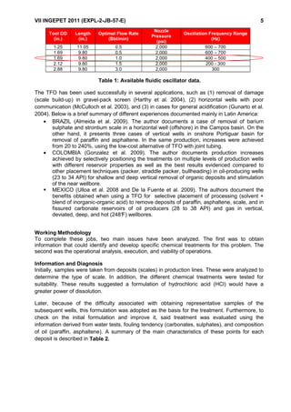
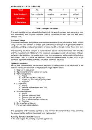
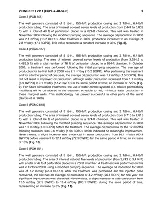
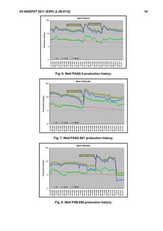
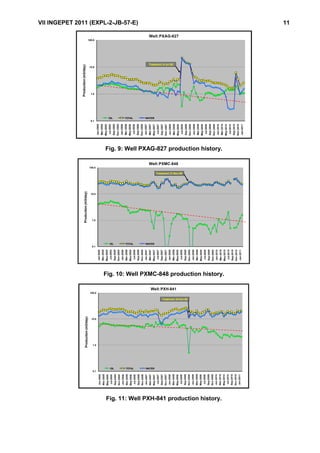
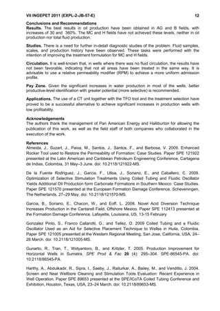
VII INGEPET 2011 (EXPL-2-JB-57-E)
Stimulation with Coiled Tubing and Fluidic Oscillation: Applications in Wells with
Low Production (Marginal Profitability) in San Jorge Gulf Area, Argentina:
Case History
Juan Bonapace (Halliburton), German Rimondi (Halliburton), Mario Bustamante (Pan
American Energy), and Rodrigo Quintavalla (Pan American Energy)
Abstract
In the area of Cerro Dragon (San Jorge Gulf basin (SJGB), Argentina), a group of wells in
different fields have shown a marked decrease in production in recent years, many of them are
affected by the secondary recovery system (waterflooding).
The causes of damage detected in these wells are principally deposits of paraffin, asphaltene,
and scales (calcium carbonate), the latter caused by the fouling tendency found in water
samples.
To increase the production of these wells, workover interventions have been frequently
conducted by hydraulic fracturing, acid treatments, and reperforating zones. Acid treatments
(near-wellbore cleanout) with a CT unit and a new tool called a true fluidic oscillator (TFO) have
been proposed to find a more cost-effective alternative.
To enhance the effect of the stimulation systems, the TFO generates a frequency of impact of
300 to 600 Hz on the formation that weakens and efficiently removes the damage. The CT
synergy, generation of fluid waves, and the selection systems for optimal acid flow through each
hole have led to significant results of reduced cost and time and improved production.
A total of twenty jobs have been performed, 75% of them showed increases in the total fluid
production; the oil production increased from 30 to 365%. This paper discusses the expertise,
results, and lessons learned in these fields.
Introduction—Reservoir Geology
The SJGB is located within the provinces of Chubut and Santa Cruz in southern Argentina. It
has an irregular shape with greater east-west elongation, having its main development in the
onshore part (65%) and the rest in the offshore area. Its genesis is of an extensional type in the
Mesozoic age; the main filling occurred in a stage of rifting from the late Jurassic to early
Cretaceous period, and the nature of the sediments is predominantly lakes and rivers.
This basin presents a two-dominant structural style; in the eastern sector, it is extensional and,
in the western sector, it is compressional (San Bernardo fold belt). The hydrocarbon traps are
mostly combined (sedimentary and structural).
The main production levels are formations, such as Mina del Carmen (formed by a continental
environment composed of lakes and rivers with light oil), Comodoro Rivadavia, and El Trebol
(fluvial continental environment of a deltaic type). Sand bodies have thicknesses of 2 to 10 m,
with porosities varying from 17 to 27%, decreasing in depth, and permeability values fluctuate.
In general, permeability values average 50 mD.
Geographic Description
VII INGEPET 2011 (EXPL-2-JB-57-E) 2
The Cerro Dragon area is located 85 km, west of the city of Comodoro Rivadavia, on the
western flank of the SJGB in the province of Chubut, Argentina (Fig. 1).
The area operated by Pan American Energy LLC consists of approximately 50 different
operational fields covering an area of nearly 3500 km2
in which 3,800 active wells are located,
with an average depth of 2200 meters. Half the oil production comes from 60 secondary-
recovery projects with a total of 650 injection wells. The Cerro Dragon field has been under
development and exploitation since 1959.
Fig. 1: Geographic location.
Background
The study area comprises four fields: AG, MC, l H, and B.
An average well in these fields experiences the following stages:
• Completion—initial period of production in the life of a well (perforations, stimulations).
• Workover interventions with different purposes—isolate water production zones, add
new productive levels, or stimulate and restimulate.
• Secondary recovery—maintaining or increasing production through different techniques.
Throughout the productive life of a well, production decline can be caused by obstruction of
perforations, scaling generation, fine-sediment production, deposition of organic material
(asphaltene and paraffin), and water blocking.
To sustain production over time, several alternatives have been applied to maintain or increase
oil production (acidification, new perforation, and hydraulic fracture) and decrease water
production (isolated levels, cementing treatments, sealing zones with conformance treatments,
and mechanical methods).
Re-perforating to bypass problem zones or zones with decreased production is a common, low-
cost practice to stabilize or increase production in this field. The results have been favorable in
most cases.
VII INGEPET 2011 (EXPL-2-JB-57-E) 3
Considering the background and characteristics of the reservoir type (multi-layer) as well as the
low availability of workover equipment, a technical and economical alternative to conventional
chemical cleaning (near-wellbore stimulation) is a method of using coiled tubing (CT) with a
TFO tool.
Technical Description—Coiled Tubing
CT technology has evolved significantly since the early 1960s, when the first CT unit was built
and used in the oilfield. As technology improved, CT began to be recognized as a reliable, cost-
effective, and fast way to perform live-well intervention. A significant breakthrough in CT
reliability took place in the 1970s and 1980s, when continuous milling came about and
manufacturing quality was improved. Before this time, CT was manufactured in 1,500-ft sections
and welded together. Higher-strength steels began to be used to manufacture tubing, adding
additional durability and strength to the system. Now, CT can be manufactured from steels with
various high yield strengths, and in sizes up to 4.5-in. OD. Fig. 2 shows a land CT unit working
on a well.
Fig. 2: Land CT unit working on a well.
True Fluidic Oscillator
The TFO tool creates pulsating pressure waves within the wellbore and formation fluids. These
pressure waves help to break up near-wellbore damage and to restore the permeability of the
formation by carrying a treatment fluid into the formation (Webb et al. 2006). The tool does not
require a packer and does not contain elastomer sealing elements, which reduces the number
of elements that can fail. The treatment fluid is then pumped through the tool, into the borehole
and the formation (Fig. 3).
VII INGEPET 2011 (EXPL-2-JB-57-E) 4
Fig. 3: Fluidic oscillator.
As fluid flows inside the tool, oscillating pressure waves are created by the Coanda effect,
discovered in 1930 by Henry Coanda. He observed that a fluid that emerges from a nozzle
tends to flow near the surface, provided that the curvature is not too accentuated.
Inside the tool, a fluid stream is repeatedly switched from one passageway to another by means
of this effect, rapidly oscillating between two different paths. This allows the tool to create
pressure waves without moving parts and without relying on cavitations. These waves are not
affected by standoff, as with conventional jetting or velocity tools. The kinetic energy travels
through fluid with little energy loss.
When the wave reaches the formation, the energy is dumped and damage removal is initiated.
As the damage is removed, the pressure waves are able to penetrate more deeply into the
formation, removing perforation-tunnel damage, scales, formation fines, mud and cement
damage, drilling damage, water and gas blocks, and asphaltene/paraffin deposits. The acoustic
streaming induced by the oscillator focuses the treatment on the immediate area of the tool. The
action of the chemical is enhanced by the increased contact area with the formation.
TFOs are available in sizes varying from 1.69- to 2.88-in. OD. This tool is adaptable to both
jointed pipe and CT applications. The tools operate at an optimal pressure drop of
approximately 2,000 psi and oscillate at a frequency between 200 to 600 Hz. The tools have
been used up to 400°F, and they are suitable for ga s service. Table 1 shows the available tool
sizes, optimal rates, nozzle pressures, and frequency ranges, and the TFO used in this case
history is indicated below.
VII INGEPET 2011 (EXPL-2-JB-57-E) 5
Table 1: Available fluidic oscillator data.
The TFO has been used successfully in several applications, such as (1) removal of damage
(scale build-up) in gravel-pack screen (Harthy et al. 2004), (2) horizontal wells with poor
communication (McCulloch et al. 2003), and (3) in cases for general acidification (Gunarto et al.
2004). Below is a brief summary of different experiences documented mainly in Latin America:
• BRAZIL (Almeida et al. 2009). The author documents a case of removal of barium
sulphate and strontium scale in a horizontal well (offshore) in the Campos basin. On the
other hand, it presents three cases of vertical wells in onshore Portiguar basin for
removal of paraffin and asphaltene. In the same production, increases were achieved
from 20 to 240%, using the low-cost alternative of TFO with joint tubing.
• COLOMBIA (Gonzalez et al. 2009). The author documents production increases
achieved by selectively positioning the treatments on multiple levels of production wells
with different reservoir properties as well as the best results evidenced compared to
other placement techniques (packer, straddle packer, bullheading) in oil-producing wells
(23 to 34 API) for shallow and deep vertical removal of organic deposits and stimulation
of the near wellbore.
MEXICO (Ulloa et al. 2008 and De la Fuente et al. 2009). The authors document the
benefits obtained when using a TFO for selective placement of processing (solvent +
blend of inorganic-organic acid) to remove deposits of paraffin, asphaltene, scale, and in
fissured carbonate reservoirs of oil producers (28 to 38 API) and gas in vertical,
deviated, deep, and hot (248°F) wellbores.
Working Methodology
To complete these jobs, two main issues have been analyzed. The first was to obtain
information that could identify and develop specific chemical treatments for this problem. The
second was the operational analysis, execution, and viability of operations.
Information and Diagnosis
Initially, samples were taken from deposits (scales) in production lines. These were analyzed to
determine the type of scale. In addition, the different chemical treatments were tested for
suitability. These results suggested a formulation of hydrochloric acid (HCl) would have a
greater power of dissolution.
Later, because of the difficulty associated with obtaining representative samples of the
subsequent wells, this formulation was adopted as the basis for the treatment. Furthermore, to
check on the initial formulation and improve it, said treatment was evaluated using the
information derived from water tests, fouling tendency (carbonates, sulphates), and composition
of oil (paraffin, asphaltene). A summary of the main characteristics of these points for each
deposit is described in Table 2.
Tool OD
(in.)
Length
(in.)
Optimal Flow Rate
(Bbl/min)
Nozzle
Pressure
(psi)
Oscillation Frequency Range
(Hz)
1.25 11.05 0.5 2,000 600 – 700
1.69 9.80 0.5 2,000 600 – 700
1.69 9.80 1.0 2,000 400 – 500
2.12 9.80 1.5 2,000 200 - 300
2.88 9.80 3.0 2,000 300
VII INGEPET 2011 (EXPL-2-JB-57-E) 6
FIELD AG MC H B
Scale (tendency) low - moderate very low very low without
% Paraffin 9 8 9 > 10
% Asphaltene 4 4 8 3
Table 2: Analysis performed.
The analysis obtained has allowed identification of the type of damage, such as organic (wax
and asphaltene) and inorganic deposits (calcium carbonate) located near the well (near-
wellbore skin).
Treatment Design
Treatments have been designed as near-wellbore stimulation to be pumped to a matrix system
using a volume ratio between 25 and 50 gal/ft perforated (an average of 30 gal/ft perforated was
used); thus, yielding a radius of penetration of about 2 to 3 ft seeking to reduce the positive skin.
The laboratory results on samples of scale indicated a base solution formulated with 10% HCl
and 5% mutual solvent. Additionally, this treatment was supplemented with corrosion inhibitor,
surfactant, clay stabilizer, penetrating agent, and iron sequestering and aromatic solvent at an
early stage. Later, to optimize the treatment, certain components were modified, such as pH
controller, a paraffin inhibitor, solvents, emulsifier, and micro-emulsion.
Operation Sequence
All the work conducted has had the same sequence of development in the preparation of the
well and subsequent execution of the production stage detailed below:
1. Stop well in production.
2. Rig down and remove surface unit pump.
3. Workover operation.
a. Rig up
b. Pull out subsurface unit pump
c. Isolate pay zone with plug and packer
d. Rig down
4. CT operation.
a. Rig up
b. Perform acid treatment with TFO
c. Rig down
5. Workover operation.
a. Rig up
b. Recover treatment fluid
c. Remove plug and packer
d. Run in hole subsurface unit pump
e. Rig down
6. Rig up surface unit pump.
7. Put well back into production.
The appropriate and necessary logistics to help minimize the nonproductive times, benefiting
the economy of the well and the project, were implemented.
Pumping Schedule: Initial Sequence
In the early stages, the pumping sequence applied was:
VII INGEPET 2011 (EXPL-2-JB-57-E) 7
1. Because the bottomhole assembly (BHA) was at the bottom of the chamber (area
between the plug and the packer), the proceeding consisted of washing this surface with
linear gel treated water.
2. While the BHA remained at the bottom, the pumping treatment was initiated (acid and
solvent).
3. The chamber was filled with treatment fluid.
4. The CT was raised to the packer.
5. The well was closed (annulus-closed) and a rundown was performed to the bottom of
the well, forcing the treatment into the formation.
6. The annulus was opened to recover as much of the surface treatment as possible, as
well as the waste material that could have remained from the chemical action.
This initial sequence of applying the treatment was carried out in the first eight operated wells
(AG). The sequence described above is shown in Fig. 4 from left to right.
Fig. 4: Initial sequence.
Pumping Schedule: Modified Sequence
The treatment placement was analyzed to improve its efficiency. This resulted in dividing the
treatment into two stages, the first one consisting of solvent, and the second one of acid
treatment. The objective was to improve the solubilization of inorganic compounds with acid
treatment. To achieve this, the solvent was pumped during the first stage, so that organic
compounds could be removed.
The new pumping sequence used was:
1. The chamber was cleaned (casing cleaning) with a solvent-based treatment.
2. The chamber was washed to remove any debris generated by this first solution.
3. Once the annulus was closed, solvent was injected to the formation to clean the near-
wellbore area.
4. In the second part of the treatment, a volume of acid solution was injected.
5. In the last stage of the sequence, the annulus was opened to recover the greatest
amount of fluid pumped (wasted acid), circulating with the CT in the downhole.
This method of applying the treatment has been used on wells AG, MC, H, and B. The
distribution mechanism is shown in Fig. 5.
2480 ft 2480 ft
2980 ft 2980 ft
CERRAR
RETORNO
ABRIR
RETORNO
Closed
annulus
Open
annulus
VII INGEPET 2011 (EXPL-2-JB-57-E) 8
Fig. 5: Modified sequence.
Case Histories
During the period from 2007 to 2009, 20 jobs in these fields were completed, showing increases
in oil production of 60% and also an increase in the total fluid produced (i.e., water + oil) in 75%
of the operated wells. Six representative cases of these fields appear below.
Case 1 (PXAG-5)
The well geometry consisted of 7-in., 20-lb/ft production casing and 2 7/8-in., 6.4 lb/ft production
tubing. The area of interest covered four levels of production (from 2,589 to 2,956 ft) with a total
of 26.5 ft of perforation placed in a 403.5-ft chamber (distance between plug and packer). Two
treatments were performed on this well. The first was in November 2007 using the initial
pumping sequence, and the second, in July 2009, was applied with the modified pumping
sequence. The average oil production for the first half of 2007 was 3.3 m³/day (20.8 BOPD). A
sudden, sharp drop between July and September, with production dropping to 2 m³/day (12.5
BOPD), was the reason for the first completion treatment performed. The resulting production
was 6.9 m³/day (43.4 BOPD); an increase of 245%. In June 2009, there was a similar drop in
production to 2.2 m³/day (13.8 BOPD). After repeating the treatment, the production reached
values of 4.9 m³/day (30.8 BOPD); an increase of 122% (Fig. 6).
Case 2 (PXAG-801)
The well geometry consisted of 5 ½-in., 15.5-lb/ft production casing and 2 7/8-in., 6.4-lb/ft
production tubing. The area of interest covered six levels of production (from 2,493 to 2,973 ft)
with a total number of 54 ft of perforation placed in a 525-ft chamber. A treatment was
performed on this well in October 2007 following the initial pumping sequence. The average oil
production before the treatment was 1.8 m³/day (11.3 BOPD). After the treatment was
performed and the injected dose recovered, the well production was 8.3 m³/day (52.2 BOPD);
an increase of 360%. In the two years following, the average oil production after the treatment
was 6.4 m³/day (40.3 BOPD) (Fig. 7).
Packer Packer Packer
Tapón Tapón Tapón
LIMPIEZA DEL CASING CON SOLVENTE FORZAMIENTO DEL SOLVENTE A LA FORMACIÓN FORZAMIENTO DEL ACIDO A LA FORMACIÓN
Casing cleaning with
solvent
Solvent Injection into
formation
Acid Injection into formation
Packer
Plug
VII INGEPET 2011 (EXPL-2-JB-57-E) 9
Case 3 (PXB-858)
The well geometry consisted of 5 ½-in., 15.5-lb/ft production casing and 2 7/8-in., 6.4-lb/ft
production tubing. The area of interest covered seven levels of production (from 2,447 to 3,032
ft) with a total of 49 ft of perforation placed in a 627-ft chamber. This well was treated in
November 2008 following the modified pumping sequence. The average oil production in 2008
was 2.1 m³/day (13.2 BOPD). After treatment in 2009, production increased to an average of
2.8 m³/day (17.6 BOPD). This value represents a constant increase of 33% (Fig. 8).
Case 4 (PXAG-827)
The well geometry consisted of 5 ½-in., 15.5-lb/ft production casing and 2 7/8-in., 6.4-lb/ft
production tubing. The area of interest covered seven levels of production (from 3,534.5 to
4,483.5 ft) with a total number of 76 ft of perforation placed in a 984-ft chamber. In October
2008, a treatment was performed following the initial pumping sequence. The average oil
production for the first half of 2008 was 2.1 m³/day (13.2 BOPD). After performing the treatment
and for a further period of one year, the average oil production was 1.2 m³/day (7.5 BOPD). This
did not result in improved oil production, although water production increased from 1.1 m³/day
(6.9 BWPD) to 9.1 m³/day (57.2 BWPD) in the same period of time; an increase of 720% (Fig.
9). For future stimulation treatments, the use of water-control systems (i.e. relative permeability
modifiers) will be considered in the treatment schedule to help minimize water production in
these marginal wells. This methodology has proved successful in other parts of the world
(Garcia et al. 2008).
Case 5 (PXMC-848)
The well geometry consisted of 5 ½-in., 15.5-lb/ft production casing and 2 7/8-in., 6.4-lb/ft
production tubing. The area of interest covered seven levels of production (from 6,713 to 7,015
ft) with a total of 64 ft of perforation placed in a 374-ft chamber. This well was treated in
November 2008, following the modified pumping sequence. The average oil production in 2008
was 1.2 m³/day (3.9 BOPD) before the treatment. The average oil production for the 12 months
following treatment was 0.6 m³/day (1.96 BOPD), which indicated no meaningful improvement.
Nevertheless, a slight increase was evidenced in water production; from 20.1 m³/day (65.9
BWPD) before treatment to 22.1 m³/day (72.5 BWPD) for the same period of time; an increase
of 10% (Fig. 10).
Case 6 (PXH-841)
The well geometry consisted of 5 ½-in., 15.5-lb/ft production casing and 2 7/8-in., 6.4-lb/ft
production tubing. The area of interest included five levels of production (from 2,743 to 3,414 ft)
with a total of 45 ft of perforation placed in a 722-ft chamber. A treatment was performed on this
well in October 2008 using a modified pumping sequence. The average oil production for 2008
was of 7.2 m³/day (45.3 BOPD). After the treatment was performed and the injected dose
recovered, the well had an average oil production of 4.2 m³/day (26.4 BOPD) for one year. No
significant improvement was observed. Nevertheless, a slight increase in water production from
15.5 m³/day (97.5 BWPD) to 16.4 m³/day (103.1 BWPD) during the same period of time,
representing an increase by 6% (Fig. 11).
VII INGEPET 2011 (EXPL-2-JB-57-E) 10
Fig. 6: Well PXAG-5 production history.
Fig. 7: Well PXAG-801 production history.
Fig. 8: Well PXB-858 production history.
0.1
1.0
10.0
100.0
Jan-2005
Mar-2005
May-2005
Jul-2005
Sep-2005
Nov-2005
Jan-2006
Mar-2006
May-2006
Jul-2006
Sep-2006
Nov-2006
Jan-2007
Mar-2007
May-2007
Jul-2007
Sep-2007
Nov-2007
Jan-2008
Mar-2008
May-2008
Jul-2008
Sep-2008
Nov-2008
Jan-2009
Mar-2009
May-2009
Jul-2009
Sep-2009
Nov-2009
Jan-2010
Mar-2010
May-2010
Jul-2010
Sep-2010
Nov-2010
Jan-2011
Production(m3/day)
Well:PXAG-5
OIL TOTAL WATER
Treatment 5-Nov-07
Treatment 5-Jul-09
0.1
1.0
10.0
100.0
Jan-2005
Mar-2005
May-2005
Jul-2005
Sep-2005
Nov-2005
Jan-2006
Mar-2006
May-2006
Jul-2006
Sep-2006
Nov-2006
Jan-2007
Mar-2007
May-2007
Jul-2007
Sep-2007
Nov-2007
Jan-2008
Mar-2008
May-2008
Jul-2008
Sep-2008
Nov-2008
Jan-2009
Mar-2009
May-2009
Jul-2009
Sep-2009
Nov-2009
Jan-2010
Mar-2010
May-2010
Jul-2010
Sep-2010
Nov-2010
Jan-2011
Production(m3/day)
Well:PXAG-801
OIL TOTAL WATER
Treatment 30-Oct-07
0.1
1.0
10.0
100.0
Jan-2005
Mar-2005
May-2005
Jul-2005
Sep-2005
Nov-2005
Jan-2006
Mar-2006
May-2006
Jul-2006
Sep-2006
Nov-2006
Jan-2007
Mar-2007
May-2007
Jul-2007
Sep-2007
Nov-2007
Jan-2008
Mar-2008
May-2008
Jul-2008
Sep-2008
Nov-2008
Jan-2009
Mar-2009
May-2009
Jul-2009
Sep-2009
Nov-2009
Jan-2010
Mar-2010
May-2010
Jul-2010
Sep-2010
Nov-2010
Jan-2011
Production(m3/day)
Well:PXB-858
OIL TOTAL WATER
Treatment 13-Nov-08
VII INGEPET 2011 (EXPL-2-JB-57-E) 11
Fig. 9: Well PXAG-827 production history.
Fig. 10: Well PXMC-848 production history.
Fig. 11: Well PXH-841 production history.
0.1
1.0
10.0
100.0
Jan-2005
Mar-2005
May-2005
Jul-2005
Sep-2005
Nov-2005
Jan-2006
Mar-2006
May-2006
Jul-2006
Sep-2006
Nov-2006
Jan-2007
Mar-2007
May-2007
Jul-2007
Sep-2007
Nov-2007
Jan-2008
Mar-2008
May-2008
Jul-2008
Sep-2008
Nov-2008
Jan-2009
Mar-2009
May-2009
Jul-2009
Sep-2009
Nov-2009
Jan-2010
Mar-2010
May-2010
Jul-2010
Sep-2010
Nov-2010
Jan-2011
Production(m3/day)
Well:PXAG-827
OIL TOTAL WATER
Treatment 9-Jul-08
0.1
1.0
10.0
100.0
Jan-2005
Mar-2005
May-2005
Jul-2005
Sep-2005
Nov-2005
Jan-2006
Mar-2006
May-2006
Jul-2006
Sep-2006
Nov-2006
Jan-2007
Mar-2007
May-2007
Jul-2007
Sep-2007
Nov-2007
Jan-2008
Mar-2008
May-2008
Jul-2008
Sep-2008
Nov-2008
Jan-2009
Mar-2009
May-2009
Jul-2009
Sep-2009
Nov-2009
Jan-2010
Mar-2010
May-2010
Jul-2010
Sep-2010
Nov-2010
Jan-2011
Production(m3/day)
Well:PXMC-848
OIL TOTAL WATER
Treatment 21-Nov-08
0.1
1.0
10.0
100.0
Jan-2005
Mar-2005
May-2005
Jul-2005
Sep-2005
Nov-2005
Jan-2006
Mar-2006
May-2006
Jul-2006
Sep-2006
Nov-2006
Jan-2007
Mar-2007
May-2007
Jul-2007
Sep-2007
Nov-2007
Jan-2008
Mar-2008
May-2008
Jul-2008
Sep-2008
Nov-2008
Jan-2009
Mar-2009
May-2009
Jul-2009
Sep-2009
Nov-2009
Jan-2010
Mar-2010
May-2010
Jul-2010
Sep-2010
Nov-2010
Jan-2011
Production(m3/day)
Well:PXH-841
OIL TOTAL WATER
Treatment 24-Oct-08
VII INGEPET 2011 (EXPL-2-JB-57-E) 12
Conclusions and Recommendations
Results. The best results in oil production have been obtained in AG and B fields, with
increases of 30 and 360%. The MC and H fields have not achieved these levels, neither in oil
production nor total fluid production.
Studies. There is a need for further in-detail diagnostic studies of the problem. Fluid samples,
scales, and production history have been observed. These tasks were performed with the
intention of improving the treatment formulation for MC and H fields.
Circulation. It is well-known that, in wells where there was no fluid circulation, the results have
not been favorable, indicating that not all areas have been treated in the same way. It is
advisable to use a relative permeability modifier (RPM) to achieve a more uniform admission
profile.
Pay Zone. Given the significant increases in water production in most of the wells, better
productive-level identification with greater potential (more selective) is recommended.
Applications. The use of a CT unit together with the TFO tool and the treatment selection have
proved to be a successful alternative to achieve significant increases in production wells with
low profitability.
Acknowledgements
The authors thank the management of Pan American Energy and Halliburton for allowing the
publication of this work, as well as the field staff of both companies who collaborated in the
execution of the work.
References
Almeida, J., Suzart, J., Paiva, M., Santos, J., Santos, F., and Barbosa, V. 2009. Enhanced
Rocker Tool used to Restore the Permeability of Formation: Case Studies. Paper SPE 121922
presented at the Latin American and Caribbean Petroleum Engineering Conference, Cartagena
de Indias, Colombia, 31 May–3 June. doi: 10.2118/121922-MS.
De la Fuente Rodriguez, J., Garcia, F., Ulloa, J., Soriano, E., and Caballero, C. 2009.
Optimization of Selective Stimulation Treatments Using Coiled Tubing and Fluidic Oscillator
Yields Additional Oil Production form Carbonate Formations in Southern Mexico: Case Studies.
Paper SPE 121570 presented at the European Formation Damage Conference, Scheveningen,
The Netherlands, 27–29 May. doi: 10.2118/121570-MS.
Garcia, B., Soriano, E., Chacon, W., and Eoff, L. 2008. Novel Acid Diversion Technique
Increases Production in the Cantarell Field, Offshore Mexico. Paper SPE 112413 presented at
the Formation Damage Conference, Lafayette, Louisiana, US, 13-15 February
Gonzalez Pinto, S., Franco Callarotti, G., and Tellez, O. 2009 Coiled Tubing and a Fluidic
Oscillator Used as an Aid for Selective Placement Technique to Wellss in Huila, Colombia.
Paper SPE 121005 presented at the Western Regional Meeting, San Jose, California, USA, 24–
26 March. doi: 10.2118/121005-MS.
Gunarto, R., Tran, T., Widyantoro, B., and Kritzler, T. 2005. Production Improvement for
Horizontal Wells in Sumatra. SPE Prod & Fac 20 (4): 295–304. SPE-86545-PA. doi:
10.2118/86545-PA.
Harthy, A., Abdulkadir, R., Sipra, I., Saeby, J., Raiturkar, A., Bailey, M., and Venditto, J. 2004.
Screen and Near Wellbore Cleaning and Stimulation Tools Evaluation: Recent Experience in
Well Operation. Paper SPE 89653 presented at the SPE/ICoTA Coiled Tubing Conference and
Exhibition, Houston, Texas, USA, 23–24 March. doi: 10.2118/89653-MS.
VII INGEPET 2011 (EXPL-2-JB-57-E) 13
McCulloch, D., Mann, J., Macmillan, P., and Ali, S. 2003. Damage Removal in Screened
Horizontal Wells. Paper SPE 81732 presented at the SPE/ICoTA Coiled Tubing Conference,
Houston, Texas, USA, 8–9 April. doi: 10.2118/81732-MS.
Ulloa Gutierrez, J.V., Franco Callarotti, G. Akrich, O., and Rodriguez Monroy, R. 2008.
Stimulation with Coiled Tubing and Fluidic Oscillation. Paper SPE 113716 presented at the
SPE/ICoTA Coiled Tubing and Well Intervention Conference and Exhibition, The Woodlands,
Texas, USA, 1–2 April. doi: 10.2118/113716-MS.
Webb, E., Schultz, R., Howard, R., and Tucker, J. 2006. Next Generation Fluidic Oscillator.
Paper SPE 99855 presented at the SPE/ICoTA Coiled Tubing and Well Intervention Conference
and Exhibition, The Woodlands, Texas, USA, 4–5 April. doi: 10.2118/99855-MS.

More Related Content

What's hot

2575150, Significant Production Improvement of UltraLow Permeability Granitic...
2575150, Significant Production Improvement of UltraLow Permeability Granitic...2575150, Significant Production Improvement of UltraLow Permeability Granitic...
2575150, Significant Production Improvement of UltraLow Permeability Granitic...Mostafa Kortam
 
Hydraulic Fracturing: Importance to the Industry
Hydraulic Fracturing: Importance to the IndustryHydraulic Fracturing: Importance to the Industry
Hydraulic Fracturing: Importance to the IndustryPorts-To-Plains Blog
 
14 aneu applications of technological & engineering solutions edit
14 aneu applications of technological & engineering solutions edit 14 aneu applications of technological & engineering solutions edit
14 aneu applications of technological & engineering solutions edit Juan Carlos Bonapace
 
Controlling Water On Construction Sites
Controlling Water On Construction SitesControlling Water On Construction Sites
Controlling Water On Construction SitesMartin Preene
 
Expandable liner hanger and packer exceed expectations for first deepwater we...
Expandable liner hanger and packer exceed expectations for first deepwater we...Expandable liner hanger and packer exceed expectations for first deepwater we...
Expandable liner hanger and packer exceed expectations for first deepwater we...Baker Hughes
 
Water dam versus Tailing Dam
Water dam versus Tailing DamWater dam versus Tailing Dam
Water dam versus Tailing Damfrank huangfu
 
Tight Reservoir Technology IUGF 20 1 2012
Tight Reservoir Technology IUGF 20 1 2012Tight Reservoir Technology IUGF 20 1 2012
Tight Reservoir Technology IUGF 20 1 2012Dev Dutt Sharma
 
Groundwater improvement techniques
Groundwater improvement techniques Groundwater improvement techniques
Groundwater improvement techniques my-will
 
Construction Dewatering PowerPoint
Construction Dewatering PowerPointConstruction Dewatering PowerPoint
Construction Dewatering PowerPointTerry Aylward
 
Coal Combustible Presentation 7 30_2015
Coal Combustible Presentation 7 30_2015Coal Combustible Presentation 7 30_2015
Coal Combustible Presentation 7 30_2015Terry Aylward
 

What's hot (20)

Spe 151819-ms
Spe 151819-msSpe 151819-ms
Spe 151819-ms
 
Spe 164580-ms
Spe 164580-msSpe 164580-ms
Spe 164580-ms
 
Spe 185478-ms
Spe 185478-msSpe 185478-ms
Spe 185478-ms
 
Spe 123010-ms
Spe 123010-msSpe 123010-ms
Spe 123010-ms
 
Spe 180818-ms ttec 2016
Spe 180818-ms ttec 2016Spe 180818-ms ttec 2016
Spe 180818-ms ttec 2016
 
2575150, Significant Production Improvement of UltraLow Permeability Granitic...
2575150, Significant Production Improvement of UltraLow Permeability Granitic...2575150, Significant Production Improvement of UltraLow Permeability Granitic...
2575150, Significant Production Improvement of UltraLow Permeability Granitic...
 
Hydraulic Fracturing: Importance to the Industry
Hydraulic Fracturing: Importance to the IndustryHydraulic Fracturing: Importance to the Industry
Hydraulic Fracturing: Importance to the Industry
 
14 aneu applications of technological & engineering solutions edit
14 aneu applications of technological & engineering solutions edit 14 aneu applications of technological & engineering solutions edit
14 aneu applications of technological & engineering solutions edit
 
SPE-15101-PA
SPE-15101-PASPE-15101-PA
SPE-15101-PA
 
Controlling Water On Construction Sites
Controlling Water On Construction SitesControlling Water On Construction Sites
Controlling Water On Construction Sites
 
Expandable liner hanger and packer exceed expectations for first deepwater we...
Expandable liner hanger and packer exceed expectations for first deepwater we...Expandable liner hanger and packer exceed expectations for first deepwater we...
Expandable liner hanger and packer exceed expectations for first deepwater we...
 
Productividad
ProductividadProductividad
Productividad
 
Shale gas presentation
Shale gas presentationShale gas presentation
Shale gas presentation
 
Water dam versus Tailing Dam
Water dam versus Tailing DamWater dam versus Tailing Dam
Water dam versus Tailing Dam
 
Tight Reservoir Technology IUGF 20 1 2012
Tight Reservoir Technology IUGF 20 1 2012Tight Reservoir Technology IUGF 20 1 2012
Tight Reservoir Technology IUGF 20 1 2012
 
tight reservoir
tight reservoir tight reservoir
tight reservoir
 
Construction dewatering technology data sheet
Construction dewatering technology data sheetConstruction dewatering technology data sheet
Construction dewatering technology data sheet
 
Groundwater improvement techniques
Groundwater improvement techniques Groundwater improvement techniques
Groundwater improvement techniques
 
Construction Dewatering PowerPoint
Construction Dewatering PowerPointConstruction Dewatering PowerPoint
Construction Dewatering PowerPoint
 
Coal Combustible Presentation 7 30_2015
Coal Combustible Presentation 7 30_2015Coal Combustible Presentation 7 30_2015
Coal Combustible Presentation 7 30_2015
 

Similar to Expl 2-jb-57-e

The great shale-gas rush new product developement
The great shale-gas rush new product developementThe great shale-gas rush new product developement
The great shale-gas rush new product developementGaurav Singh
 
Case study Read the following case study and write your report about t.pdf
Case study Read the following case study and write your report about t.pdfCase study Read the following case study and write your report about t.pdf
Case study Read the following case study and write your report about t.pdfakknit
 
Cdw sed tank_tech_memo1111
Cdw sed tank_tech_memo1111Cdw sed tank_tech_memo1111
Cdw sed tank_tech_memo1111Mazen Alqadi
 
Abstract This case study examines the formation damage that occurred i.pdf
Abstract This case study examines the formation damage that occurred i.pdfAbstract This case study examines the formation damage that occurred i.pdf
Abstract This case study examines the formation damage that occurred i.pdfatozbazar
 
Hydrodynamic cavitation tool
Hydrodynamic cavitation toolHydrodynamic cavitation tool
Hydrodynamic cavitation toolerdemsecen
 
A case study on blowout and its control in krishna godavari (kg) basin, east ...
A case study on blowout and its control in krishna godavari (kg) basin, east ...A case study on blowout and its control in krishna godavari (kg) basin, east ...
A case study on blowout and its control in krishna godavari (kg) basin, east ...Alexander Decker
 
11.a case study on blowout and its control in krishna godavari (kg) basin, ea...
11.a case study on blowout and its control in krishna godavari (kg) basin, ea...11.a case study on blowout and its control in krishna godavari (kg) basin, ea...
11.a case study on blowout and its control in krishna godavari (kg) basin, ea...Alexander Decker
 
Gulf of Mexico Hydrate Mounds
Gulf of Mexico Hydrate MoundsGulf of Mexico Hydrate Mounds
Gulf of Mexico Hydrate MoundsB.Nicole Barry
 
Creating a Worldwide Unconventional Revolution Through a Technically Driven S...
Creating a Worldwide Unconventional Revolution Through a Technically Driven S...Creating a Worldwide Unconventional Revolution Through a Technically Driven S...
Creating a Worldwide Unconventional Revolution Through a Technically Driven S...Society of Petroleum Engineers
 
SPE JPT - 2008 9 tech update
SPE JPT - 2008 9 tech updateSPE JPT - 2008 9 tech update
SPE JPT - 2008 9 tech updateManuel S. Navarro
 

Similar to Expl 2-jb-57-e (20)

SPE WVS-593.
SPE WVS-593. SPE WVS-593.
SPE WVS-593.
 
Ejge
EjgeEjge
Ejge
 
The great shale-gas rush new product developement
The great shale-gas rush new product developementThe great shale-gas rush new product developement
The great shale-gas rush new product developement
 
Case study Read the following case study and write your report about t.pdf
Case study Read the following case study and write your report about t.pdfCase study Read the following case study and write your report about t.pdf
Case study Read the following case study and write your report about t.pdf
 
SPE-147389-PA
SPE-147389-PASPE-147389-PA
SPE-147389-PA
 
SPE-178786-MS
SPE-178786-MSSPE-178786-MS
SPE-178786-MS
 
Cdw sed tank_tech_memo1111
Cdw sed tank_tech_memo1111Cdw sed tank_tech_memo1111
Cdw sed tank_tech_memo1111
 
SPE-10022.pdf
SPE-10022.pdfSPE-10022.pdf
SPE-10022.pdf
 
Abstract This case study examines the formation damage that occurred i.pdf
Abstract This case study examines the formation damage that occurred i.pdfAbstract This case study examines the formation damage that occurred i.pdf
Abstract This case study examines the formation damage that occurred i.pdf
 
POSTER (Original)
POSTER (Original)POSTER (Original)
POSTER (Original)
 
Hydrodynamic cavitation tool
Hydrodynamic cavitation toolHydrodynamic cavitation tool
Hydrodynamic cavitation tool
 
A case study on blowout and its control in krishna godavari (kg) basin, east ...
A case study on blowout and its control in krishna godavari (kg) basin, east ...A case study on blowout and its control in krishna godavari (kg) basin, east ...
A case study on blowout and its control in krishna godavari (kg) basin, east ...
 
A case study on blowout and its control in krishna godavari (kg) basin, east ...
A case study on blowout and its control in krishna godavari (kg) basin, east ...A case study on blowout and its control in krishna godavari (kg) basin, east ...
A case study on blowout and its control in krishna godavari (kg) basin, east ...
 
11.a case study on blowout and its control in krishna godavari (kg) basin, ea...
11.a case study on blowout and its control in krishna godavari (kg) basin, ea...11.a case study on blowout and its control in krishna godavari (kg) basin, ea...
11.a case study on blowout and its control in krishna godavari (kg) basin, ea...
 
Gulf of Mexico Hydrate Mounds
Gulf of Mexico Hydrate MoundsGulf of Mexico Hydrate Mounds
Gulf of Mexico Hydrate Mounds
 
Spe 119460-ms
Spe 119460-msSpe 119460-ms
Spe 119460-ms
 
Creating a Worldwide Unconventional Revolution Through a Technically Driven S...
Creating a Worldwide Unconventional Revolution Through a Technically Driven S...Creating a Worldwide Unconventional Revolution Through a Technically Driven S...
Creating a Worldwide Unconventional Revolution Through a Technically Driven S...
 
H0372040043
H0372040043H0372040043
H0372040043
 
IPTC_12_2015
IPTC_12_2015IPTC_12_2015
IPTC_12_2015
 
SPE JPT - 2008 9 tech update
SPE JPT - 2008 9 tech updateSPE JPT - 2008 9 tech update
SPE JPT - 2008 9 tech update
 

More from Juan Carlos Bonapace

Multipay Well Completion in Argentina: A Versatile Pinpoint Completion Techno...
Multipay Well Completion in Argentina: A Versatile Pinpoint Completion Techno...Multipay Well Completion in Argentina: A Versatile Pinpoint Completion Techno...
Multipay Well Completion in Argentina: A Versatile Pinpoint Completion Techno...Juan Carlos Bonapace
 
Technological Aadvances Hydraulic Fracture
Technological Aadvances Hydraulic FractureTechnological Aadvances Hydraulic Fracture
Technological Aadvances Hydraulic FractureJuan Carlos Bonapace
 
Logistica proppant no convencional v1
Logistica proppant no convencional v1Logistica proppant no convencional v1
Logistica proppant no convencional v1Juan Carlos Bonapace
 
Iapg jornadas shale neuquén vm completion in existing wells- 2013 neuquén
Iapg jornadas shale neuquén vm completion in existing wells- 2013 neuquénIapg jornadas shale neuquén vm completion in existing wells- 2013 neuquén
Iapg jornadas shale neuquén vm completion in existing wells- 2013 neuquénJuan Carlos Bonapace
 
Iapg jornadas shale neuquén vaca muerta a regional vision- 2013 neuquén
Iapg jornadas shale neuquén vaca muerta a regional vision- 2013 neuquénIapg jornadas shale neuquén vaca muerta a regional vision- 2013 neuquén
Iapg jornadas shale neuquén vaca muerta a regional vision- 2013 neuquénJuan Carlos Bonapace
 
Conexplo proppant management 2014 mendoza
Conexplo proppant management 2014 mendozaConexplo proppant management 2014 mendoza
Conexplo proppant management 2014 mendozaJuan Carlos Bonapace
 
IAPG - Jornadas Perforacion y Terminación 2011, CR-Arg
IAPG - Jornadas Perforacion y Terminación 2011, CR-ArgIAPG - Jornadas Perforacion y Terminación 2011, CR-Arg
IAPG - Jornadas Perforacion y Terminación 2011, CR-ArgJuan Carlos Bonapace
 

More from Juan Carlos Bonapace (15)

SPE-212574-MS.pdf
SPE-212574-MS.pdfSPE-212574-MS.pdf
SPE-212574-MS.pdf
 
SPE-212571-MS.pdf
SPE-212571-MS.pdfSPE-212571-MS.pdf
SPE-212571-MS.pdf
 
Presentation_SPE-212571-MS.pptx
Presentation_SPE-212571-MS.pptxPresentation_SPE-212571-MS.pptx
Presentation_SPE-212571-MS.pptx
 
Presentation_SPE-212574-MS.pptx
Presentation_SPE-212574-MS.pptxPresentation_SPE-212574-MS.pptx
Presentation_SPE-212574-MS.pptx
 
Multipay Well Completion in Argentina: A Versatile Pinpoint Completion Techno...
Multipay Well Completion in Argentina: A Versatile Pinpoint Completion Techno...Multipay Well Completion in Argentina: A Versatile Pinpoint Completion Techno...
Multipay Well Completion in Argentina: A Versatile Pinpoint Completion Techno...
 
Technological Aadvances Hydraulic Fracture
Technological Aadvances Hydraulic FractureTechnological Aadvances Hydraulic Fracture
Technological Aadvances Hydraulic Fracture
 
Logistica proppant no convencional v1
Logistica proppant no convencional v1Logistica proppant no convencional v1
Logistica proppant no convencional v1
 
Iapg jornadas shale neuquén vm completion in existing wells- 2013 neuquén
Iapg jornadas shale neuquén vm completion in existing wells- 2013 neuquénIapg jornadas shale neuquén vm completion in existing wells- 2013 neuquén
Iapg jornadas shale neuquén vm completion in existing wells- 2013 neuquén
 
Iapg jornadas shale neuquén vaca muerta a regional vision- 2013 neuquén
Iapg jornadas shale neuquén vaca muerta a regional vision- 2013 neuquénIapg jornadas shale neuquén vaca muerta a regional vision- 2013 neuquén
Iapg jornadas shale neuquén vaca muerta a regional vision- 2013 neuquén
 
Conexplo proppant management 2014 mendoza
Conexplo proppant management 2014 mendozaConexplo proppant management 2014 mendoza
Conexplo proppant management 2014 mendoza
 
Expl 2-jb-57-e INGEPET VII 2011
Expl 2-jb-57-e INGEPET VII 2011Expl 2-jb-57-e INGEPET VII 2011
Expl 2-jb-57-e INGEPET VII 2011
 
IAPG - Jornadas Perforacion y Terminación 2011, CR-Arg
IAPG - Jornadas Perforacion y Terminación 2011, CR-ArgIAPG - Jornadas Perforacion y Terminación 2011, CR-Arg
IAPG - Jornadas Perforacion y Terminación 2011, CR-Arg
 
SPE. WMOG-15 session i
SPE. WMOG-15 session i SPE. WMOG-15 session i
SPE. WMOG-15 session i
 
SPE-172724
SPE-172724SPE-172724
SPE-172724
 
SPE-174118
SPE-174118SPE-174118
SPE-174118
 

Recently uploaded

Call Girls Service Nagpur Tanvi Call 7001035870 Meet With Nagpur Escorts
Call Girls Service Nagpur Tanvi Call 7001035870 Meet With Nagpur EscortsCall Girls Service Nagpur Tanvi Call 7001035870 Meet With Nagpur Escorts
Call Girls Service Nagpur Tanvi Call 7001035870 Meet With Nagpur EscortsCall Girls in Nagpur High Profile
 
Decoding Kotlin - Your guide to solving the mysterious in Kotlin.pptx
Decoding Kotlin - Your guide to solving the mysterious in Kotlin.pptxDecoding Kotlin - Your guide to solving the mysterious in Kotlin.pptx
Decoding Kotlin - Your guide to solving the mysterious in Kotlin.pptxJoão Esperancinha
 
Architect Hassan Khalil Portfolio for 2024
Architect Hassan Khalil Portfolio for 2024Architect Hassan Khalil Portfolio for 2024
Architect Hassan Khalil Portfolio for 2024hassan khalil
 
Internship report on mechanical engineering
Internship report on mechanical engineeringInternship report on mechanical engineering
Internship report on mechanical engineeringmalavadedarshan25
 
Current Transformer Drawing and GTP for MSETCL
Current Transformer Drawing and GTP for MSETCLCurrent Transformer Drawing and GTP for MSETCL
Current Transformer Drawing and GTP for MSETCLDeelipZope
 
Sheet Pile Wall Design and Construction: A Practical Guide for Civil Engineer...
Sheet Pile Wall Design and Construction: A Practical Guide for Civil Engineer...Sheet Pile Wall Design and Construction: A Practical Guide for Civil Engineer...
Sheet Pile Wall Design and Construction: A Practical Guide for Civil Engineer...Dr.Costas Sachpazis
 
MANUFACTURING PROCESS-II UNIT-5 NC MACHINE TOOLS
MANUFACTURING PROCESS-II UNIT-5 NC MACHINE TOOLSMANUFACTURING PROCESS-II UNIT-5 NC MACHINE TOOLS
MANUFACTURING PROCESS-II UNIT-5 NC MACHINE TOOLSSIVASHANKAR N
 
Biology for Computer Engineers Course Handout.pptx
Biology for Computer Engineers Course Handout.pptxBiology for Computer Engineers Course Handout.pptx
Biology for Computer Engineers Course Handout.pptxDeepakSakkari2
 
Microscopic Analysis of Ceramic Materials.pptx
Microscopic Analysis of Ceramic Materials.pptxMicroscopic Analysis of Ceramic Materials.pptx
Microscopic Analysis of Ceramic Materials.pptxpurnimasatapathy1234
 
Coefficient of Thermal Expansion and their Importance.pptx
Coefficient of Thermal Expansion and their Importance.pptxCoefficient of Thermal Expansion and their Importance.pptx
Coefficient of Thermal Expansion and their Importance.pptxAsutosh Ranjan
 
HARMONY IN THE NATURE AND EXISTENCE - Unit-IV
HARMONY IN THE NATURE AND EXISTENCE - Unit-IVHARMONY IN THE NATURE AND EXISTENCE - Unit-IV
HARMONY IN THE NATURE AND EXISTENCE - Unit-IVRajaP95
 
Call Girls Delhi {Jodhpur} 9711199012 high profile service
Call Girls Delhi {Jodhpur} 9711199012 high profile serviceCall Girls Delhi {Jodhpur} 9711199012 high profile service
Call Girls Delhi {Jodhpur} 9711199012 high profile servicerehmti665
 
GDSC ASEB Gen AI study jams presentation
GDSC ASEB Gen AI study jams presentationGDSC ASEB Gen AI study jams presentation
GDSC ASEB Gen AI study jams presentationGDSCAESB
 
(MEERA) Dapodi Call Girls Just Call 7001035870 [ Cash on Delivery ] Pune Escorts
(MEERA) Dapodi Call Girls Just Call 7001035870 [ Cash on Delivery ] Pune Escorts(MEERA) Dapodi Call Girls Just Call 7001035870 [ Cash on Delivery ] Pune Escorts
(MEERA) Dapodi Call Girls Just Call 7001035870 [ Cash on Delivery ] Pune Escortsranjana rawat
 
IVE Industry Focused Event - Defence Sector 2024
IVE Industry Focused Event - Defence Sector 2024IVE Industry Focused Event - Defence Sector 2024
IVE Industry Focused Event - Defence Sector 2024Mark Billinghurst
 
Introduction to Multiple Access Protocol.pptx
Introduction to Multiple Access Protocol.pptxIntroduction to Multiple Access Protocol.pptx
Introduction to Multiple Access Protocol.pptxupamatechverse
 
OSVC_Meta-Data based Simulation Automation to overcome Verification Challenge...
OSVC_Meta-Data based Simulation Automation to overcome Verification Challenge...OSVC_Meta-Data based Simulation Automation to overcome Verification Challenge...
OSVC_Meta-Data based Simulation Automation to overcome Verification Challenge...Soham Mondal
 
Analog to Digital and Digital to Analog Converter
Analog to Digital and Digital to Analog ConverterAnalog to Digital and Digital to Analog Converter
Analog to Digital and Digital to Analog ConverterAbhinavSharma374939
 
High Profile Call Girls Nagpur Isha Call 7001035870 Meet With Nagpur Escorts
High Profile Call Girls Nagpur Isha Call 7001035870 Meet With Nagpur EscortsHigh Profile Call Girls Nagpur Isha Call 7001035870 Meet With Nagpur Escorts
High Profile Call Girls Nagpur Isha Call 7001035870 Meet With Nagpur Escortsranjana rawat
 
Processing & Properties of Floor and Wall Tiles.pptx
Processing & Properties of Floor and Wall Tiles.pptxProcessing & Properties of Floor and Wall Tiles.pptx
Processing & Properties of Floor and Wall Tiles.pptxpranjaldaimarysona
 

Recently uploaded (20)

Call Girls Service Nagpur Tanvi Call 7001035870 Meet With Nagpur Escorts
Call Girls Service Nagpur Tanvi Call 7001035870 Meet With Nagpur EscortsCall Girls Service Nagpur Tanvi Call 7001035870 Meet With Nagpur Escorts
Call Girls Service Nagpur Tanvi Call 7001035870 Meet With Nagpur Escorts
 
Decoding Kotlin - Your guide to solving the mysterious in Kotlin.pptx
Decoding Kotlin - Your guide to solving the mysterious in Kotlin.pptxDecoding Kotlin - Your guide to solving the mysterious in Kotlin.pptx
Decoding Kotlin - Your guide to solving the mysterious in Kotlin.pptx
 
Architect Hassan Khalil Portfolio for 2024
Architect Hassan Khalil Portfolio for 2024Architect Hassan Khalil Portfolio for 2024
Architect Hassan Khalil Portfolio for 2024
 
Internship report on mechanical engineering
Internship report on mechanical engineeringInternship report on mechanical engineering
Internship report on mechanical engineering
 
Current Transformer Drawing and GTP for MSETCL
Current Transformer Drawing and GTP for MSETCLCurrent Transformer Drawing and GTP for MSETCL
Current Transformer Drawing and GTP for MSETCL
 
Sheet Pile Wall Design and Construction: A Practical Guide for Civil Engineer...
Sheet Pile Wall Design and Construction: A Practical Guide for Civil Engineer...Sheet Pile Wall Design and Construction: A Practical Guide for Civil Engineer...
Sheet Pile Wall Design and Construction: A Practical Guide for Civil Engineer...
 
MANUFACTURING PROCESS-II UNIT-5 NC MACHINE TOOLS
MANUFACTURING PROCESS-II UNIT-5 NC MACHINE TOOLSMANUFACTURING PROCESS-II UNIT-5 NC MACHINE TOOLS
MANUFACTURING PROCESS-II UNIT-5 NC MACHINE TOOLS
 
Biology for Computer Engineers Course Handout.pptx
Biology for Computer Engineers Course Handout.pptxBiology for Computer Engineers Course Handout.pptx
Biology for Computer Engineers Course Handout.pptx
 
Microscopic Analysis of Ceramic Materials.pptx
Microscopic Analysis of Ceramic Materials.pptxMicroscopic Analysis of Ceramic Materials.pptx
Microscopic Analysis of Ceramic Materials.pptx
 
Coefficient of Thermal Expansion and their Importance.pptx
Coefficient of Thermal Expansion and their Importance.pptxCoefficient of Thermal Expansion and their Importance.pptx
Coefficient of Thermal Expansion and their Importance.pptx
 
HARMONY IN THE NATURE AND EXISTENCE - Unit-IV
HARMONY IN THE NATURE AND EXISTENCE - Unit-IVHARMONY IN THE NATURE AND EXISTENCE - Unit-IV
HARMONY IN THE NATURE AND EXISTENCE - Unit-IV
 
Call Girls Delhi {Jodhpur} 9711199012 high profile service
Call Girls Delhi {Jodhpur} 9711199012 high profile serviceCall Girls Delhi {Jodhpur} 9711199012 high profile service
Call Girls Delhi {Jodhpur} 9711199012 high profile service
 
GDSC ASEB Gen AI study jams presentation
GDSC ASEB Gen AI study jams presentationGDSC ASEB Gen AI study jams presentation
GDSC ASEB Gen AI study jams presentation
 
(MEERA) Dapodi Call Girls Just Call 7001035870 [ Cash on Delivery ] Pune Escorts
(MEERA) Dapodi Call Girls Just Call 7001035870 [ Cash on Delivery ] Pune Escorts(MEERA) Dapodi Call Girls Just Call 7001035870 [ Cash on Delivery ] Pune Escorts
(MEERA) Dapodi Call Girls Just Call 7001035870 [ Cash on Delivery ] Pune Escorts
 
IVE Industry Focused Event - Defence Sector 2024
IVE Industry Focused Event - Defence Sector 2024IVE Industry Focused Event - Defence Sector 2024
IVE Industry Focused Event - Defence Sector 2024
 
Introduction to Multiple Access Protocol.pptx
Introduction to Multiple Access Protocol.pptxIntroduction to Multiple Access Protocol.pptx
Introduction to Multiple Access Protocol.pptx
 
OSVC_Meta-Data based Simulation Automation to overcome Verification Challenge...
OSVC_Meta-Data based Simulation Automation to overcome Verification Challenge...OSVC_Meta-Data based Simulation Automation to overcome Verification Challenge...
OSVC_Meta-Data based Simulation Automation to overcome Verification Challenge...
 
Analog to Digital and Digital to Analog Converter
Analog to Digital and Digital to Analog ConverterAnalog to Digital and Digital to Analog Converter
Analog to Digital and Digital to Analog Converter
 
High Profile Call Girls Nagpur Isha Call 7001035870 Meet With Nagpur Escorts
High Profile Call Girls Nagpur Isha Call 7001035870 Meet With Nagpur EscortsHigh Profile Call Girls Nagpur Isha Call 7001035870 Meet With Nagpur Escorts
High Profile Call Girls Nagpur Isha Call 7001035870 Meet With Nagpur Escorts
 
Processing & Properties of Floor and Wall Tiles.pptx
Processing & Properties of Floor and Wall Tiles.pptxProcessing & Properties of Floor and Wall Tiles.pptx
Processing & Properties of Floor and Wall Tiles.pptx
 

Expl 2-jb-57-e

  • 1. VII INGEPET 2011 (EXPL-2-JB-57-E) Stimulation with Coiled Tubing and Fluidic Oscillation: Applications in Wells with Low Production (Marginal Profitability) in San Jorge Gulf Area, Argentina: Case History Juan Bonapace (Halliburton), German Rimondi (Halliburton), Mario Bustamante (Pan American Energy), and Rodrigo Quintavalla (Pan American Energy) Abstract In the area of Cerro Dragon (San Jorge Gulf basin (SJGB), Argentina), a group of wells in different fields have shown a marked decrease in production in recent years, many of them are affected by the secondary recovery system (waterflooding). The causes of damage detected in these wells are principally deposits of paraffin, asphaltene, and scales (calcium carbonate), the latter caused by the fouling tendency found in water samples. To increase the production of these wells, workover interventions have been frequently conducted by hydraulic fracturing, acid treatments, and reperforating zones. Acid treatments (near-wellbore cleanout) with a CT unit and a new tool called a true fluidic oscillator (TFO) have been proposed to find a more cost-effective alternative. To enhance the effect of the stimulation systems, the TFO generates a frequency of impact of 300 to 600 Hz on the formation that weakens and efficiently removes the damage. The CT synergy, generation of fluid waves, and the selection systems for optimal acid flow through each hole have led to significant results of reduced cost and time and improved production. A total of twenty jobs have been performed, 75% of them showed increases in the total fluid production; the oil production increased from 30 to 365%. This paper discusses the expertise, results, and lessons learned in these fields. Introduction—Reservoir Geology The SJGB is located within the provinces of Chubut and Santa Cruz in southern Argentina. It has an irregular shape with greater east-west elongation, having its main development in the onshore part (65%) and the rest in the offshore area. Its genesis is of an extensional type in the Mesozoic age; the main filling occurred in a stage of rifting from the late Jurassic to early Cretaceous period, and the nature of the sediments is predominantly lakes and rivers. This basin presents a two-dominant structural style; in the eastern sector, it is extensional and, in the western sector, it is compressional (San Bernardo fold belt). The hydrocarbon traps are mostly combined (sedimentary and structural). The main production levels are formations, such as Mina del Carmen (formed by a continental environment composed of lakes and rivers with light oil), Comodoro Rivadavia, and El Trebol (fluvial continental environment of a deltaic type). Sand bodies have thicknesses of 2 to 10 m, with porosities varying from 17 to 27%, decreasing in depth, and permeability values fluctuate. In general, permeability values average 50 mD. Geographic Description
  • 2. VII INGEPET 2011 (EXPL-2-JB-57-E) 2 The Cerro Dragon area is located 85 km, west of the city of Comodoro Rivadavia, on the western flank of the SJGB in the province of Chubut, Argentina (Fig. 1). The area operated by Pan American Energy LLC consists of approximately 50 different operational fields covering an area of nearly 3500 km2 in which 3,800 active wells are located, with an average depth of 2200 meters. Half the oil production comes from 60 secondary- recovery projects with a total of 650 injection wells. The Cerro Dragon field has been under development and exploitation since 1959. Fig. 1: Geographic location. Background The study area comprises four fields: AG, MC, l H, and B. An average well in these fields experiences the following stages: • Completion—initial period of production in the life of a well (perforations, stimulations). • Workover interventions with different purposes—isolate water production zones, add new productive levels, or stimulate and restimulate. • Secondary recovery—maintaining or increasing production through different techniques. Throughout the productive life of a well, production decline can be caused by obstruction of perforations, scaling generation, fine-sediment production, deposition of organic material (asphaltene and paraffin), and water blocking. To sustain production over time, several alternatives have been applied to maintain or increase oil production (acidification, new perforation, and hydraulic fracture) and decrease water production (isolated levels, cementing treatments, sealing zones with conformance treatments, and mechanical methods). Re-perforating to bypass problem zones or zones with decreased production is a common, low- cost practice to stabilize or increase production in this field. The results have been favorable in most cases.
  • 3. VII INGEPET 2011 (EXPL-2-JB-57-E) 3 Considering the background and characteristics of the reservoir type (multi-layer) as well as the low availability of workover equipment, a technical and economical alternative to conventional chemical cleaning (near-wellbore stimulation) is a method of using coiled tubing (CT) with a TFO tool. Technical Description—Coiled Tubing CT technology has evolved significantly since the early 1960s, when the first CT unit was built and used in the oilfield. As technology improved, CT began to be recognized as a reliable, cost- effective, and fast way to perform live-well intervention. A significant breakthrough in CT reliability took place in the 1970s and 1980s, when continuous milling came about and manufacturing quality was improved. Before this time, CT was manufactured in 1,500-ft sections and welded together. Higher-strength steels began to be used to manufacture tubing, adding additional durability and strength to the system. Now, CT can be manufactured from steels with various high yield strengths, and in sizes up to 4.5-in. OD. Fig. 2 shows a land CT unit working on a well. Fig. 2: Land CT unit working on a well. True Fluidic Oscillator The TFO tool creates pulsating pressure waves within the wellbore and formation fluids. These pressure waves help to break up near-wellbore damage and to restore the permeability of the formation by carrying a treatment fluid into the formation (Webb et al. 2006). The tool does not require a packer and does not contain elastomer sealing elements, which reduces the number of elements that can fail. The treatment fluid is then pumped through the tool, into the borehole and the formation (Fig. 3).
  • 4. VII INGEPET 2011 (EXPL-2-JB-57-E) 4 Fig. 3: Fluidic oscillator. As fluid flows inside the tool, oscillating pressure waves are created by the Coanda effect, discovered in 1930 by Henry Coanda. He observed that a fluid that emerges from a nozzle tends to flow near the surface, provided that the curvature is not too accentuated. Inside the tool, a fluid stream is repeatedly switched from one passageway to another by means of this effect, rapidly oscillating between two different paths. This allows the tool to create pressure waves without moving parts and without relying on cavitations. These waves are not affected by standoff, as with conventional jetting or velocity tools. The kinetic energy travels through fluid with little energy loss. When the wave reaches the formation, the energy is dumped and damage removal is initiated. As the damage is removed, the pressure waves are able to penetrate more deeply into the formation, removing perforation-tunnel damage, scales, formation fines, mud and cement damage, drilling damage, water and gas blocks, and asphaltene/paraffin deposits. The acoustic streaming induced by the oscillator focuses the treatment on the immediate area of the tool. The action of the chemical is enhanced by the increased contact area with the formation. TFOs are available in sizes varying from 1.69- to 2.88-in. OD. This tool is adaptable to both jointed pipe and CT applications. The tools operate at an optimal pressure drop of approximately 2,000 psi and oscillate at a frequency between 200 to 600 Hz. The tools have been used up to 400°F, and they are suitable for ga s service. Table 1 shows the available tool sizes, optimal rates, nozzle pressures, and frequency ranges, and the TFO used in this case history is indicated below.
  • 5. VII INGEPET 2011 (EXPL-2-JB-57-E) 5 Table 1: Available fluidic oscillator data. The TFO has been used successfully in several applications, such as (1) removal of damage (scale build-up) in gravel-pack screen (Harthy et al. 2004), (2) horizontal wells with poor communication (McCulloch et al. 2003), and (3) in cases for general acidification (Gunarto et al. 2004). Below is a brief summary of different experiences documented mainly in Latin America: • BRAZIL (Almeida et al. 2009). The author documents a case of removal of barium sulphate and strontium scale in a horizontal well (offshore) in the Campos basin. On the other hand, it presents three cases of vertical wells in onshore Portiguar basin for removal of paraffin and asphaltene. In the same production, increases were achieved from 20 to 240%, using the low-cost alternative of TFO with joint tubing. • COLOMBIA (Gonzalez et al. 2009). The author documents production increases achieved by selectively positioning the treatments on multiple levels of production wells with different reservoir properties as well as the best results evidenced compared to other placement techniques (packer, straddle packer, bullheading) in oil-producing wells (23 to 34 API) for shallow and deep vertical removal of organic deposits and stimulation of the near wellbore. MEXICO (Ulloa et al. 2008 and De la Fuente et al. 2009). The authors document the benefits obtained when using a TFO for selective placement of processing (solvent + blend of inorganic-organic acid) to remove deposits of paraffin, asphaltene, scale, and in fissured carbonate reservoirs of oil producers (28 to 38 API) and gas in vertical, deviated, deep, and hot (248°F) wellbores. Working Methodology To complete these jobs, two main issues have been analyzed. The first was to obtain information that could identify and develop specific chemical treatments for this problem. The second was the operational analysis, execution, and viability of operations. Information and Diagnosis Initially, samples were taken from deposits (scales) in production lines. These were analyzed to determine the type of scale. In addition, the different chemical treatments were tested for suitability. These results suggested a formulation of hydrochloric acid (HCl) would have a greater power of dissolution. Later, because of the difficulty associated with obtaining representative samples of the subsequent wells, this formulation was adopted as the basis for the treatment. Furthermore, to check on the initial formulation and improve it, said treatment was evaluated using the information derived from water tests, fouling tendency (carbonates, sulphates), and composition of oil (paraffin, asphaltene). A summary of the main characteristics of these points for each deposit is described in Table 2. Tool OD (in.) Length (in.) Optimal Flow Rate (Bbl/min) Nozzle Pressure (psi) Oscillation Frequency Range (Hz) 1.25 11.05 0.5 2,000 600 – 700 1.69 9.80 0.5 2,000 600 – 700 1.69 9.80 1.0 2,000 400 – 500 2.12 9.80 1.5 2,000 200 - 300 2.88 9.80 3.0 2,000 300
  • 6. VII INGEPET 2011 (EXPL-2-JB-57-E) 6 FIELD AG MC H B Scale (tendency) low - moderate very low very low without % Paraffin 9 8 9 > 10 % Asphaltene 4 4 8 3 Table 2: Analysis performed. The analysis obtained has allowed identification of the type of damage, such as organic (wax and asphaltene) and inorganic deposits (calcium carbonate) located near the well (near- wellbore skin). Treatment Design Treatments have been designed as near-wellbore stimulation to be pumped to a matrix system using a volume ratio between 25 and 50 gal/ft perforated (an average of 30 gal/ft perforated was used); thus, yielding a radius of penetration of about 2 to 3 ft seeking to reduce the positive skin. The laboratory results on samples of scale indicated a base solution formulated with 10% HCl and 5% mutual solvent. Additionally, this treatment was supplemented with corrosion inhibitor, surfactant, clay stabilizer, penetrating agent, and iron sequestering and aromatic solvent at an early stage. Later, to optimize the treatment, certain components were modified, such as pH controller, a paraffin inhibitor, solvents, emulsifier, and micro-emulsion. Operation Sequence All the work conducted has had the same sequence of development in the preparation of the well and subsequent execution of the production stage detailed below: 1. Stop well in production. 2. Rig down and remove surface unit pump. 3. Workover operation. a. Rig up b. Pull out subsurface unit pump c. Isolate pay zone with plug and packer d. Rig down 4. CT operation. a. Rig up b. Perform acid treatment with TFO c. Rig down 5. Workover operation. a. Rig up b. Recover treatment fluid c. Remove plug and packer d. Run in hole subsurface unit pump e. Rig down 6. Rig up surface unit pump. 7. Put well back into production. The appropriate and necessary logistics to help minimize the nonproductive times, benefiting the economy of the well and the project, were implemented. Pumping Schedule: Initial Sequence In the early stages, the pumping sequence applied was:
  • 7. VII INGEPET 2011 (EXPL-2-JB-57-E) 7 1. Because the bottomhole assembly (BHA) was at the bottom of the chamber (area between the plug and the packer), the proceeding consisted of washing this surface with linear gel treated water. 2. While the BHA remained at the bottom, the pumping treatment was initiated (acid and solvent). 3. The chamber was filled with treatment fluid. 4. The CT was raised to the packer. 5. The well was closed (annulus-closed) and a rundown was performed to the bottom of the well, forcing the treatment into the formation. 6. The annulus was opened to recover as much of the surface treatment as possible, as well as the waste material that could have remained from the chemical action. This initial sequence of applying the treatment was carried out in the first eight operated wells (AG). The sequence described above is shown in Fig. 4 from left to right. Fig. 4: Initial sequence. Pumping Schedule: Modified Sequence The treatment placement was analyzed to improve its efficiency. This resulted in dividing the treatment into two stages, the first one consisting of solvent, and the second one of acid treatment. The objective was to improve the solubilization of inorganic compounds with acid treatment. To achieve this, the solvent was pumped during the first stage, so that organic compounds could be removed. The new pumping sequence used was: 1. The chamber was cleaned (casing cleaning) with a solvent-based treatment. 2. The chamber was washed to remove any debris generated by this first solution. 3. Once the annulus was closed, solvent was injected to the formation to clean the near- wellbore area. 4. In the second part of the treatment, a volume of acid solution was injected. 5. In the last stage of the sequence, the annulus was opened to recover the greatest amount of fluid pumped (wasted acid), circulating with the CT in the downhole. This method of applying the treatment has been used on wells AG, MC, H, and B. The distribution mechanism is shown in Fig. 5. 2480 ft 2480 ft 2980 ft 2980 ft CERRAR RETORNO ABRIR RETORNO Closed annulus Open annulus
  • 8. VII INGEPET 2011 (EXPL-2-JB-57-E) 8 Fig. 5: Modified sequence. Case Histories During the period from 2007 to 2009, 20 jobs in these fields were completed, showing increases in oil production of 60% and also an increase in the total fluid produced (i.e., water + oil) in 75% of the operated wells. Six representative cases of these fields appear below. Case 1 (PXAG-5) The well geometry consisted of 7-in., 20-lb/ft production casing and 2 7/8-in., 6.4 lb/ft production tubing. The area of interest covered four levels of production (from 2,589 to 2,956 ft) with a total of 26.5 ft of perforation placed in a 403.5-ft chamber (distance between plug and packer). Two treatments were performed on this well. The first was in November 2007 using the initial pumping sequence, and the second, in July 2009, was applied with the modified pumping sequence. The average oil production for the first half of 2007 was 3.3 m³/day (20.8 BOPD). A sudden, sharp drop between July and September, with production dropping to 2 m³/day (12.5 BOPD), was the reason for the first completion treatment performed. The resulting production was 6.9 m³/day (43.4 BOPD); an increase of 245%. In June 2009, there was a similar drop in production to 2.2 m³/day (13.8 BOPD). After repeating the treatment, the production reached values of 4.9 m³/day (30.8 BOPD); an increase of 122% (Fig. 6). Case 2 (PXAG-801) The well geometry consisted of 5 ½-in., 15.5-lb/ft production casing and 2 7/8-in., 6.4-lb/ft production tubing. The area of interest covered six levels of production (from 2,493 to 2,973 ft) with a total number of 54 ft of perforation placed in a 525-ft chamber. A treatment was performed on this well in October 2007 following the initial pumping sequence. The average oil production before the treatment was 1.8 m³/day (11.3 BOPD). After the treatment was performed and the injected dose recovered, the well production was 8.3 m³/day (52.2 BOPD); an increase of 360%. In the two years following, the average oil production after the treatment was 6.4 m³/day (40.3 BOPD) (Fig. 7). Packer Packer Packer Tapón Tapón Tapón LIMPIEZA DEL CASING CON SOLVENTE FORZAMIENTO DEL SOLVENTE A LA FORMACIÓN FORZAMIENTO DEL ACIDO A LA FORMACIÓN Casing cleaning with solvent Solvent Injection into formation Acid Injection into formation Packer Plug
  • 9. VII INGEPET 2011 (EXPL-2-JB-57-E) 9 Case 3 (PXB-858) The well geometry consisted of 5 ½-in., 15.5-lb/ft production casing and 2 7/8-in., 6.4-lb/ft production tubing. The area of interest covered seven levels of production (from 2,447 to 3,032 ft) with a total of 49 ft of perforation placed in a 627-ft chamber. This well was treated in November 2008 following the modified pumping sequence. The average oil production in 2008 was 2.1 m³/day (13.2 BOPD). After treatment in 2009, production increased to an average of 2.8 m³/day (17.6 BOPD). This value represents a constant increase of 33% (Fig. 8). Case 4 (PXAG-827) The well geometry consisted of 5 ½-in., 15.5-lb/ft production casing and 2 7/8-in., 6.4-lb/ft production tubing. The area of interest covered seven levels of production (from 3,534.5 to 4,483.5 ft) with a total number of 76 ft of perforation placed in a 984-ft chamber. In October 2008, a treatment was performed following the initial pumping sequence. The average oil production for the first half of 2008 was 2.1 m³/day (13.2 BOPD). After performing the treatment and for a further period of one year, the average oil production was 1.2 m³/day (7.5 BOPD). This did not result in improved oil production, although water production increased from 1.1 m³/day (6.9 BWPD) to 9.1 m³/day (57.2 BWPD) in the same period of time; an increase of 720% (Fig. 9). For future stimulation treatments, the use of water-control systems (i.e. relative permeability modifiers) will be considered in the treatment schedule to help minimize water production in these marginal wells. This methodology has proved successful in other parts of the world (Garcia et al. 2008). Case 5 (PXMC-848) The well geometry consisted of 5 ½-in., 15.5-lb/ft production casing and 2 7/8-in., 6.4-lb/ft production tubing. The area of interest covered seven levels of production (from 6,713 to 7,015 ft) with a total of 64 ft of perforation placed in a 374-ft chamber. This well was treated in November 2008, following the modified pumping sequence. The average oil production in 2008 was 1.2 m³/day (3.9 BOPD) before the treatment. The average oil production for the 12 months following treatment was 0.6 m³/day (1.96 BOPD), which indicated no meaningful improvement. Nevertheless, a slight increase was evidenced in water production; from 20.1 m³/day (65.9 BWPD) before treatment to 22.1 m³/day (72.5 BWPD) for the same period of time; an increase of 10% (Fig. 10). Case 6 (PXH-841) The well geometry consisted of 5 ½-in., 15.5-lb/ft production casing and 2 7/8-in., 6.4-lb/ft production tubing. The area of interest included five levels of production (from 2,743 to 3,414 ft) with a total of 45 ft of perforation placed in a 722-ft chamber. A treatment was performed on this well in October 2008 using a modified pumping sequence. The average oil production for 2008 was of 7.2 m³/day (45.3 BOPD). After the treatment was performed and the injected dose recovered, the well had an average oil production of 4.2 m³/day (26.4 BOPD) for one year. No significant improvement was observed. Nevertheless, a slight increase in water production from 15.5 m³/day (97.5 BWPD) to 16.4 m³/day (103.1 BWPD) during the same period of time, representing an increase by 6% (Fig. 11).
  • 10. VII INGEPET 2011 (EXPL-2-JB-57-E) 10 Fig. 6: Well PXAG-5 production history. Fig. 7: Well PXAG-801 production history. Fig. 8: Well PXB-858 production history. 0.1 1.0 10.0 100.0 Jan-2005 Mar-2005 May-2005 Jul-2005 Sep-2005 Nov-2005 Jan-2006 Mar-2006 May-2006 Jul-2006 Sep-2006 Nov-2006 Jan-2007 Mar-2007 May-2007 Jul-2007 Sep-2007 Nov-2007 Jan-2008 Mar-2008 May-2008 Jul-2008 Sep-2008 Nov-2008 Jan-2009 Mar-2009 May-2009 Jul-2009 Sep-2009 Nov-2009 Jan-2010 Mar-2010 May-2010 Jul-2010 Sep-2010 Nov-2010 Jan-2011 Production(m3/day) Well:PXAG-5 OIL TOTAL WATER Treatment 5-Nov-07 Treatment 5-Jul-09 0.1 1.0 10.0 100.0 Jan-2005 Mar-2005 May-2005 Jul-2005 Sep-2005 Nov-2005 Jan-2006 Mar-2006 May-2006 Jul-2006 Sep-2006 Nov-2006 Jan-2007 Mar-2007 May-2007 Jul-2007 Sep-2007 Nov-2007 Jan-2008 Mar-2008 May-2008 Jul-2008 Sep-2008 Nov-2008 Jan-2009 Mar-2009 May-2009 Jul-2009 Sep-2009 Nov-2009 Jan-2010 Mar-2010 May-2010 Jul-2010 Sep-2010 Nov-2010 Jan-2011 Production(m3/day) Well:PXAG-801 OIL TOTAL WATER Treatment 30-Oct-07 0.1 1.0 10.0 100.0 Jan-2005 Mar-2005 May-2005 Jul-2005 Sep-2005 Nov-2005 Jan-2006 Mar-2006 May-2006 Jul-2006 Sep-2006 Nov-2006 Jan-2007 Mar-2007 May-2007 Jul-2007 Sep-2007 Nov-2007 Jan-2008 Mar-2008 May-2008 Jul-2008 Sep-2008 Nov-2008 Jan-2009 Mar-2009 May-2009 Jul-2009 Sep-2009 Nov-2009 Jan-2010 Mar-2010 May-2010 Jul-2010 Sep-2010 Nov-2010 Jan-2011 Production(m3/day) Well:PXB-858 OIL TOTAL WATER Treatment 13-Nov-08
  • 11. VII INGEPET 2011 (EXPL-2-JB-57-E) 11 Fig. 9: Well PXAG-827 production history. Fig. 10: Well PXMC-848 production history. Fig. 11: Well PXH-841 production history. 0.1 1.0 10.0 100.0 Jan-2005 Mar-2005 May-2005 Jul-2005 Sep-2005 Nov-2005 Jan-2006 Mar-2006 May-2006 Jul-2006 Sep-2006 Nov-2006 Jan-2007 Mar-2007 May-2007 Jul-2007 Sep-2007 Nov-2007 Jan-2008 Mar-2008 May-2008 Jul-2008 Sep-2008 Nov-2008 Jan-2009 Mar-2009 May-2009 Jul-2009 Sep-2009 Nov-2009 Jan-2010 Mar-2010 May-2010 Jul-2010 Sep-2010 Nov-2010 Jan-2011 Production(m3/day) Well:PXAG-827 OIL TOTAL WATER Treatment 9-Jul-08 0.1 1.0 10.0 100.0 Jan-2005 Mar-2005 May-2005 Jul-2005 Sep-2005 Nov-2005 Jan-2006 Mar-2006 May-2006 Jul-2006 Sep-2006 Nov-2006 Jan-2007 Mar-2007 May-2007 Jul-2007 Sep-2007 Nov-2007 Jan-2008 Mar-2008 May-2008 Jul-2008 Sep-2008 Nov-2008 Jan-2009 Mar-2009 May-2009 Jul-2009 Sep-2009 Nov-2009 Jan-2010 Mar-2010 May-2010 Jul-2010 Sep-2010 Nov-2010 Jan-2011 Production(m3/day) Well:PXMC-848 OIL TOTAL WATER Treatment 21-Nov-08 0.1 1.0 10.0 100.0 Jan-2005 Mar-2005 May-2005 Jul-2005 Sep-2005 Nov-2005 Jan-2006 Mar-2006 May-2006 Jul-2006 Sep-2006 Nov-2006 Jan-2007 Mar-2007 May-2007 Jul-2007 Sep-2007 Nov-2007 Jan-2008 Mar-2008 May-2008 Jul-2008 Sep-2008 Nov-2008 Jan-2009 Mar-2009 May-2009 Jul-2009 Sep-2009 Nov-2009 Jan-2010 Mar-2010 May-2010 Jul-2010 Sep-2010 Nov-2010 Jan-2011 Production(m3/day) Well:PXH-841 OIL TOTAL WATER Treatment 24-Oct-08
  • 12. VII INGEPET 2011 (EXPL-2-JB-57-E) 12 Conclusions and Recommendations Results. The best results in oil production have been obtained in AG and B fields, with increases of 30 and 360%. The MC and H fields have not achieved these levels, neither in oil production nor total fluid production. Studies. There is a need for further in-detail diagnostic studies of the problem. Fluid samples, scales, and production history have been observed. These tasks were performed with the intention of improving the treatment formulation for MC and H fields. Circulation. It is well-known that, in wells where there was no fluid circulation, the results have not been favorable, indicating that not all areas have been treated in the same way. It is advisable to use a relative permeability modifier (RPM) to achieve a more uniform admission profile. Pay Zone. Given the significant increases in water production in most of the wells, better productive-level identification with greater potential (more selective) is recommended. Applications. The use of a CT unit together with the TFO tool and the treatment selection have proved to be a successful alternative to achieve significant increases in production wells with low profitability. Acknowledgements The authors thank the management of Pan American Energy and Halliburton for allowing the publication of this work, as well as the field staff of both companies who collaborated in the execution of the work. References Almeida, J., Suzart, J., Paiva, M., Santos, J., Santos, F., and Barbosa, V. 2009. Enhanced Rocker Tool used to Restore the Permeability of Formation: Case Studies. Paper SPE 121922 presented at the Latin American and Caribbean Petroleum Engineering Conference, Cartagena de Indias, Colombia, 31 May–3 June. doi: 10.2118/121922-MS. De la Fuente Rodriguez, J., Garcia, F., Ulloa, J., Soriano, E., and Caballero, C. 2009. Optimization of Selective Stimulation Treatments Using Coiled Tubing and Fluidic Oscillator Yields Additional Oil Production form Carbonate Formations in Southern Mexico: Case Studies. Paper SPE 121570 presented at the European Formation Damage Conference, Scheveningen, The Netherlands, 27–29 May. doi: 10.2118/121570-MS. Garcia, B., Soriano, E., Chacon, W., and Eoff, L. 2008. Novel Acid Diversion Technique Increases Production in the Cantarell Field, Offshore Mexico. Paper SPE 112413 presented at the Formation Damage Conference, Lafayette, Louisiana, US, 13-15 February Gonzalez Pinto, S., Franco Callarotti, G., and Tellez, O. 2009 Coiled Tubing and a Fluidic Oscillator Used as an Aid for Selective Placement Technique to Wellss in Huila, Colombia. Paper SPE 121005 presented at the Western Regional Meeting, San Jose, California, USA, 24– 26 March. doi: 10.2118/121005-MS. Gunarto, R., Tran, T., Widyantoro, B., and Kritzler, T. 2005. Production Improvement for Horizontal Wells in Sumatra. SPE Prod & Fac 20 (4): 295–304. SPE-86545-PA. doi: 10.2118/86545-PA. Harthy, A., Abdulkadir, R., Sipra, I., Saeby, J., Raiturkar, A., Bailey, M., and Venditto, J. 2004. Screen and Near Wellbore Cleaning and Stimulation Tools Evaluation: Recent Experience in Well Operation. Paper SPE 89653 presented at the SPE/ICoTA Coiled Tubing Conference and Exhibition, Houston, Texas, USA, 23–24 March. doi: 10.2118/89653-MS.
  • 13. VII INGEPET 2011 (EXPL-2-JB-57-E) 13 McCulloch, D., Mann, J., Macmillan, P., and Ali, S. 2003. Damage Removal in Screened Horizontal Wells. Paper SPE 81732 presented at the SPE/ICoTA Coiled Tubing Conference, Houston, Texas, USA, 8–9 April. doi: 10.2118/81732-MS. Ulloa Gutierrez, J.V., Franco Callarotti, G. Akrich, O., and Rodriguez Monroy, R. 2008. Stimulation with Coiled Tubing and Fluidic Oscillation. Paper SPE 113716 presented at the SPE/ICoTA Coiled Tubing and Well Intervention Conference and Exhibition, The Woodlands, Texas, USA, 1–2 April. doi: 10.2118/113716-MS. Webb, E., Schultz, R., Howard, R., and Tucker, J. 2006. Next Generation Fluidic Oscillator. Paper SPE 99855 presented at the SPE/ICoTA Coiled Tubing and Well Intervention Conference and Exhibition, The Woodlands, Texas, USA, 4–5 April. doi: 10.2118/99855-MS.