The paper presents a new approach for regulating the output voltage of a self-excited induction generator (SEIG) driven by a variable-speed DC motor using a proportional-integral (PI) control method. A MATLAB Simulink model is developed and compared with experimental results obtained from a dSPACE board, confirming the high performance and effectiveness of the proposed system in maintaining a constant AC voltage amidst variations in load and rotor speed. Overall, the study highlights the potential for using a voltage source inverter (VSI) in renewable energy applications while addressing challenges like voltage regulation and harmonic distortion.
![International Journal of Power Electronics and Drive System (IJPEDS)
Vol. 8, No. 3, September 2017, pp. 1368~1380
ISSN: 2088-8694, DOI: 10.11591/ijpeds.v8i3.pp1368-1380 1368
Journal homepage: http://iaesjournal.com/online/index.php/IJPEDS
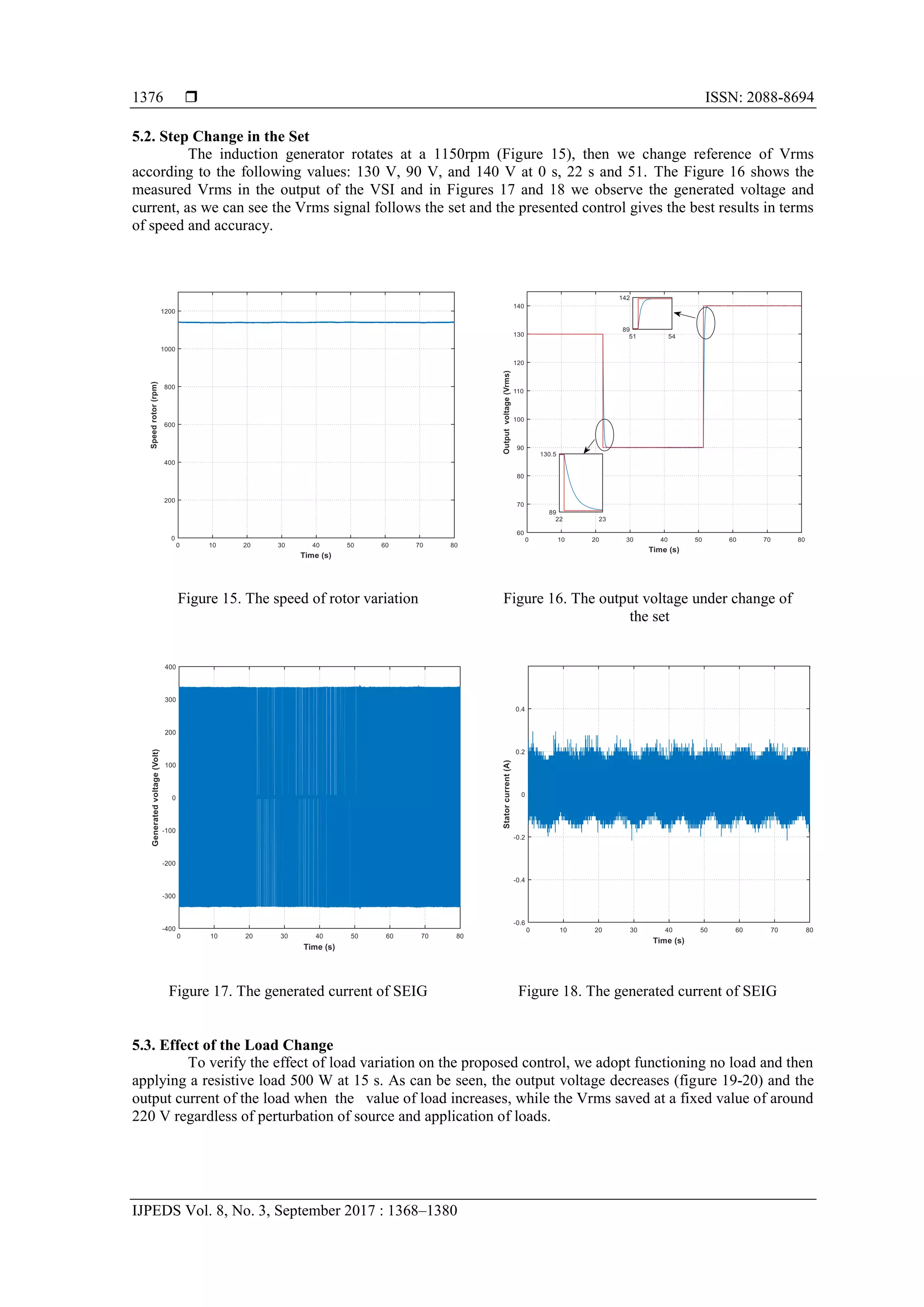
Experimental dSPACE Analysis for Self-excited Induction
Generator Used in Voltage Control
Rachid El Akhrif, Ahmed Abbou, Mohamed Barara, Mohamed Akherraz, Youssef Majdoub
Mohammadia School of Engineers, Mohammed V University, Rabat, Morocco
Article Info ABSTRACT
Article history:
Received Mar 19, 2017
Revised Jun 10, 2017
Accepted Aug 14, 2017
In this paper, a new approach is proposed for keeping the RMS voltage
output constant, the system is supplying by a self-excited induction generator
(SEIG) driven by a controlled DC motor with variable speed and load. The
scheme used in this paper is based on a classical Proportional-Integral
regulator wich controls a SPWM switching. A MATLAB Simulink model of
the system is developed to maintain the AC voltage at the desired value.
Then a comparison is examined between simulation and experimental results
using dSPACE board. The results are provided to verify the effectiveness of
this approach and it gives very high performance.
Keyword:
dSPACE Implementation
PI control
Stand alone generator
Three-phase voltage source
inverter
Wind energy
Copyright ©2017 Institute of Advanced Engineering and Science.
All rights reserved.
Corresponding Author:
Rachid El Akhrif,
Department of Electrical Engineering,
Mohammadia School of engineers,
Mohammed V University,
Avenue Ibn Sina, Rabat 10000, Morocco.
Email: elakhrif@gmail
1. INTRODUCTION
Energy production using renewable natural resources such as the wind has became an obligation in
recent years account their positive effects, especially in remote areas where the self-excited induction
generator (SEIG) is the most used [1]. The difficulty of the use of this kind of generator are the regulation
and control of frequency and voltage, and also the very bad power factor.
There is some parameters that influences the variation and the change of magnitude of voltage
produced by the generator and the frequency which are the rotor speed, the capacitance of excitation and the
change of load [2]. To solve this problem, several studies were dedicated [3] by using an advanced power
electronic converters, all the variable parameters (voltage and frequency) in the output of the SEIG are
converted into constant values.
This configuration uses different sources of direct current, which is considered an advantage for
applications with renewable energy sources since it allows generating different voltage levels at the output to
suit the use. However this still has limitations namely the imbalance of power between the generators versus
consumption.
The disadvantage of Three-phase source inverter (VSI) is the THD voltage (Total harmonic
distortion) [4] this value should not go over 5 per cent, according to the guidelines of the IEEE Standard
519-1992. Generally, there are many ways to generate a voltage output with low distortion. among these
methods are mentioned series and shunt compensation or hybrid series active power filters which can be used
for the exclusion of harmonics when nonlinear loads [5] are coupled to a VSI [6, 7]. On the other hand, we
can use the optimum fixed LC compensator, which is considered to reduce the expected value of the total
THD, while it is highly preferable to keep a specific value of the power factor (PF) [8, 9].](https://image.slidesharecdn.com/8381-9537-1-pb-210608022759/75/Experimental-dSPACE-Analysis-for-Self-excited-Induction-Generator-Used-in-Voltage-Control-1-2048.jpg)
![IJPEDS ISSN: 2088-8694
Experimental dSPACE Analysis for SEIG used in Voltage Control (Rachid El Akhrif)
1369
Another constraint is added, it is the great variability of wind speed in the case of a wind power
plant and the change of solar radiation in the case of a photovoltaic plant this obviously affects the quality of
the energy which will cause major disruptions on the connected load. The VSI proposed may be the solution
to generate electricity of good quality despite these disturbances. This kind of converter has been much
recent interest in recent years and this is especially due to the large number of its advantages in practice.
The research that preceded this work, deals with many control techniques for generating the output
voltage with a good quality and without distortions, purely a sinusoidal waveforms. First, in [10] a classical
proportional-integral (PI) controller was investigated and secondly a PI-derivative (PID) controllers for the
single-phase inverter was treated in [11]. In this context, the present work concerns a stand-alone system
based on a voltage source inverter and feeding by a SEIG then we present a experimental study of the system
performance.
The three phase full bridge diode rectifier is feeding by the voltage output of the SEIG and converts
the alternative power to a variable DC voltage. The effect of the wind is represented by the prime mover
which also leads to a variable RMS output voltage of the inverter.The objective is to regulate the output
voltage by using the closed-loop control scheme that why a classical PI controller is considered to obtain the
appropriate modulation index (mi) used in sinusoidal pulse-width modulation (SPWM), and finally we create
the different permutation which can take the VSI. The output of the system contains a lot of distortions and
the THD is very haigh. So, we connect a passive filter before transferring power to the loads [12].
The outline of this paper is done as the following: in first section we talk about the system
configuration and we propose the PI regulator used with the SPWM switching scheme. In the second section,
the simulation, the experimental results and the corresponding analysis are presented. Finally, in the last
section we end up this paper with a conclusion.
2. SYSTEM CONFIGURATION
In this section we present the stand-alone generator, which is designed for feeding a three phase
load, Figure 1 shows a schematic of our system. The pargraphes below discuss mathematical equations that
model the components of the system considered namely the SEIG, AC/DC converter, the VSI and LC filter.
Figure 1. Configuration of the proposed system
2.1. SEIG Mathematical Model
Practically we consider the dynamic model of the SEIG. It can be calculated from the classical
model by modifying the conventional dynamic equations of an AC machine, this is presented in the works of
M.Basic [13]. The classic dynamic model SEIG expressed in the Laplace domain and suitable for use in
MATLAB Simulink is described in the stationary reference frame by the following 1 differential Order:](https://image.slidesharecdn.com/8381-9537-1-pb-210608022759/75/Experimental-dSPACE-Analysis-for-Self-excited-Induction-Generator-Used-in-Voltage-Control-2-2048.jpg)
![ ISSN: 2088-8694
IJPEDS Vol. 8, No. 3, September 2017 : 1368–1380
1370
)
(
1 2
r
m
s
r
r
r
m
r
r
r
m
s
s
r
s
r
m
r
s
s K
L
u
L
i
R
L
i
L
L
i
R
L
i
L
L
L
si
)
(
1 2
r
m
s
r
r
r
r
m
r
r
m
s
r
m
s
s
r
r
s
s K
L
u
L
i
L
L
i
R
L
i
L
i
R
L
L
L
si
(1)
)
(
1
r
s
s
m
r
r
s
r
r
r
s
s
m
r
s
s
s
m
r
s
r K
L
u
L
i
R
L
i
L
L
i
L
L
i
R
L
L
L
si
)
(
1
r
s
s
m
r
r
r
s
r
r
s
s
m
r
s
s
s
m
r
s
r K
L
u
L
i
L
L
i
R
L
i
L
L
i
R
L
L
L
si
Where:
a.
s
u and
s
u
are the α-axis and β-axis component of the stator phase voltage space-vector;
b.
s
i and
s
i
are the α-axis and β-axis component of the stator phase current space-vector;
c.
r
i and
r
i
are the α-axis and β-axis component of the rotor phase current space-vector;
d. s
R and r
R are the stator and rotor resistance, respectively;
e. s
L , r
L and m
L are the stator inductance, the rotor inductance and the magnetizing inductance, respectively;
f. r
is the rotor angular speed;
g. is the total leakage factor;
h.
r
K and
r
K
are the α-axis and β-axis component of the voltage initially induced due to the residual rotor
flux linkage.
s
r
r
r
+ -
R
i
s
i
s
u
m
i
r
i
s
R s
L r
L
r
R
m
L
C
R
S
Figure 2. The equivalent schematic of the SEIG
The Equation that describe the voltage in the DC link is:
0
0
1
dc
dc
t
dc u
dt
i
C
u
(2)
Figure 2 shows the conventional SEIG equivalent circuit described by (1). An experimental test of the
machine object of the study was has given magnetization curve which represents. The variation of
magnetizing inductance (Lm) in function of phase voltage for induction machine [14].
2.2. Three Phase AC/DC Converter
A rectifier is an electrical machine that transfers AC current, which has a sinusoidal waveforms, to
DC current, which flows in only one direction. The circuit is composed of 6 diodes: a group of three in the
top and a group of three in the bottom.
](https://image.slidesharecdn.com/8381-9537-1-pb-210608022759/75/Experimental-dSPACE-Analysis-for-Self-excited-Induction-Generator-Used-in-Voltage-Control-3-2048.jpg)
![IJPEDS ISSN: 2088-8694
Experimental dSPACE Analysis for SEIG used in Voltage Control (Rachid El Akhrif)
1371
Figure 3. Three-phase AC/DC converter
2.3. Three-Phase Source Voltage Inverter
A power inverter, is an electronic device that converts DC current to AC current. The VSI has three-
switching states as described in Table 1, obtained by different permutations of the six switches Sa, Sb, Sc,
Sa', Sb' and Sc'. For supplying the power to the loads. We use a three voltage source inverter which is
represented in the Figure 4, It is used to generate and keep the alternating output voltage at a fixed value (220
Vrms), with 50 Hz frequency and with differents types of loads in isolated power generation systems. We
note that the outputs (voltage and current) depends on the scheme of the control permutations state outputs.
Figure 4. Three-phase DC/AC inverter
Table 1. The switching statesof the inverter
Sa Sb Sc Sa' Sb' Sc' Uab Ubc Uca
1 0 1 0 1 0 0 0 0
0 1 0 1 1 0 0 -Udc Udc
1 0 0 1 1 0 Udc -Udc 0
0 1 1 0 1 0 -Udc 0 Udc
1 0 1 0 0 1 0 Udc -Udc
0 1 0 1 0 1 0 0 0
1 0 0 1 0 1 Udc 0 -Udc
0 1 1 0 0 1 -Udc Udc 0
3. PROPOSED SCHEME OF CONTROL: PI REGULATOR CONNECTED WITH THE SPWM
PERMUTATIONS
The main of this section is to define the scheme of control employed in the three-phase inverter in
the stand-alone power generation system, so we use a classical Proportional-Integral regulator wich controls
a SPWM switching. The Figure 4 represents the proposed configuration to regulate and keep the output
voltage at 220 Vrms in different uses (change of loads) with a 50 Hz constant frequency [15].
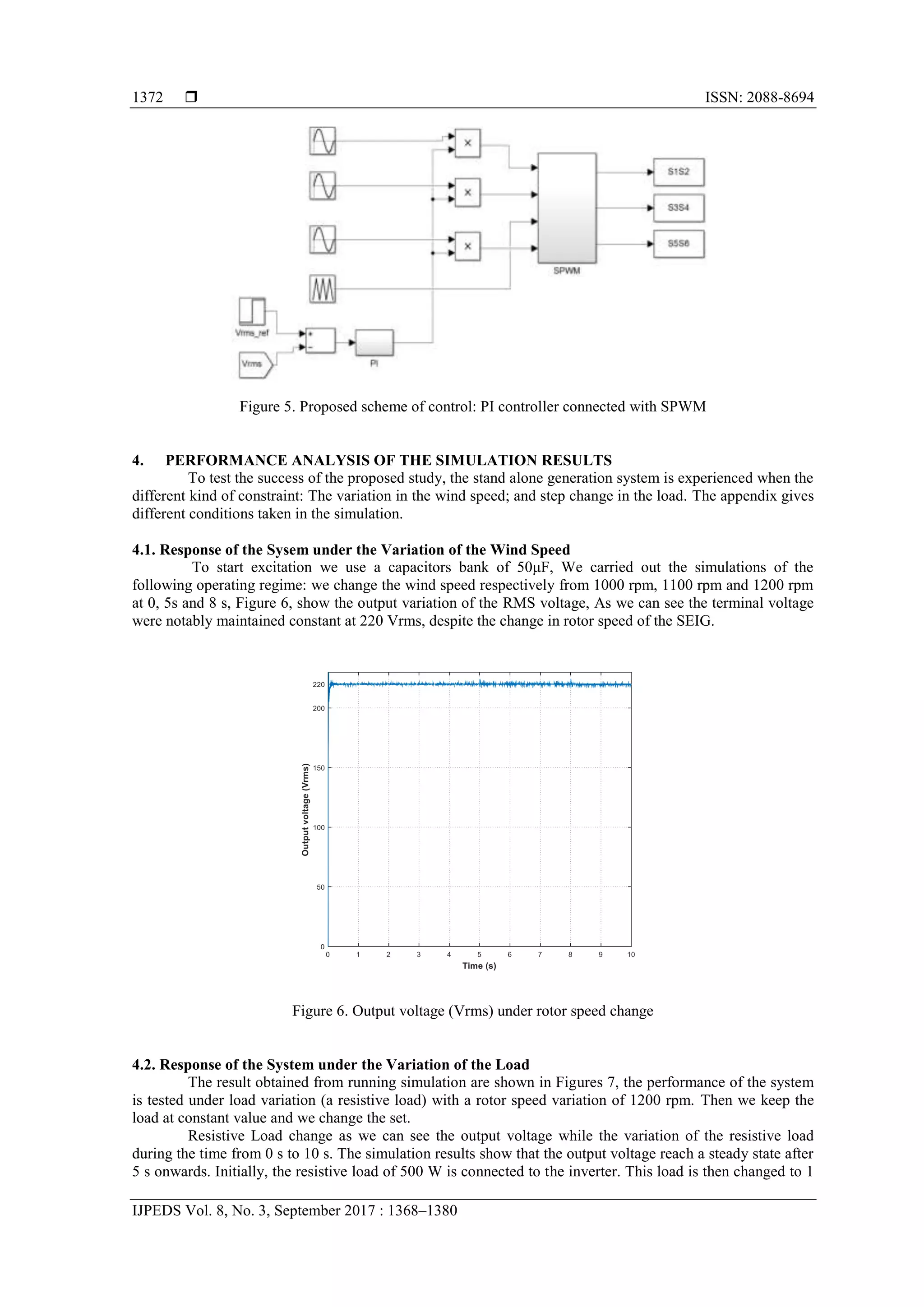
Figure 5 illustrates the Simulink model of the proposed controller. It's composed from a 3-level
PWM inverter with sinusoidal modulation, then we compare the control signal at a desired output frequency
with multilevel triangular waveforms [16-17].](https://image.slidesharecdn.com/8381-9537-1-pb-210608022759/75/Experimental-dSPACE-Analysis-for-Self-excited-Induction-Generator-Used-in-Voltage-Control-4-2048.jpg)
![IJPEDS ISSN: 2088-8694
Experimental dSPACE Analysis for SEIG used in Voltage Control (Rachid El Akhrif)
1379
Figure 25. The generated voltage of SEIG during
load variation
Figure 26. The generated voltage of SEIG during load
variation
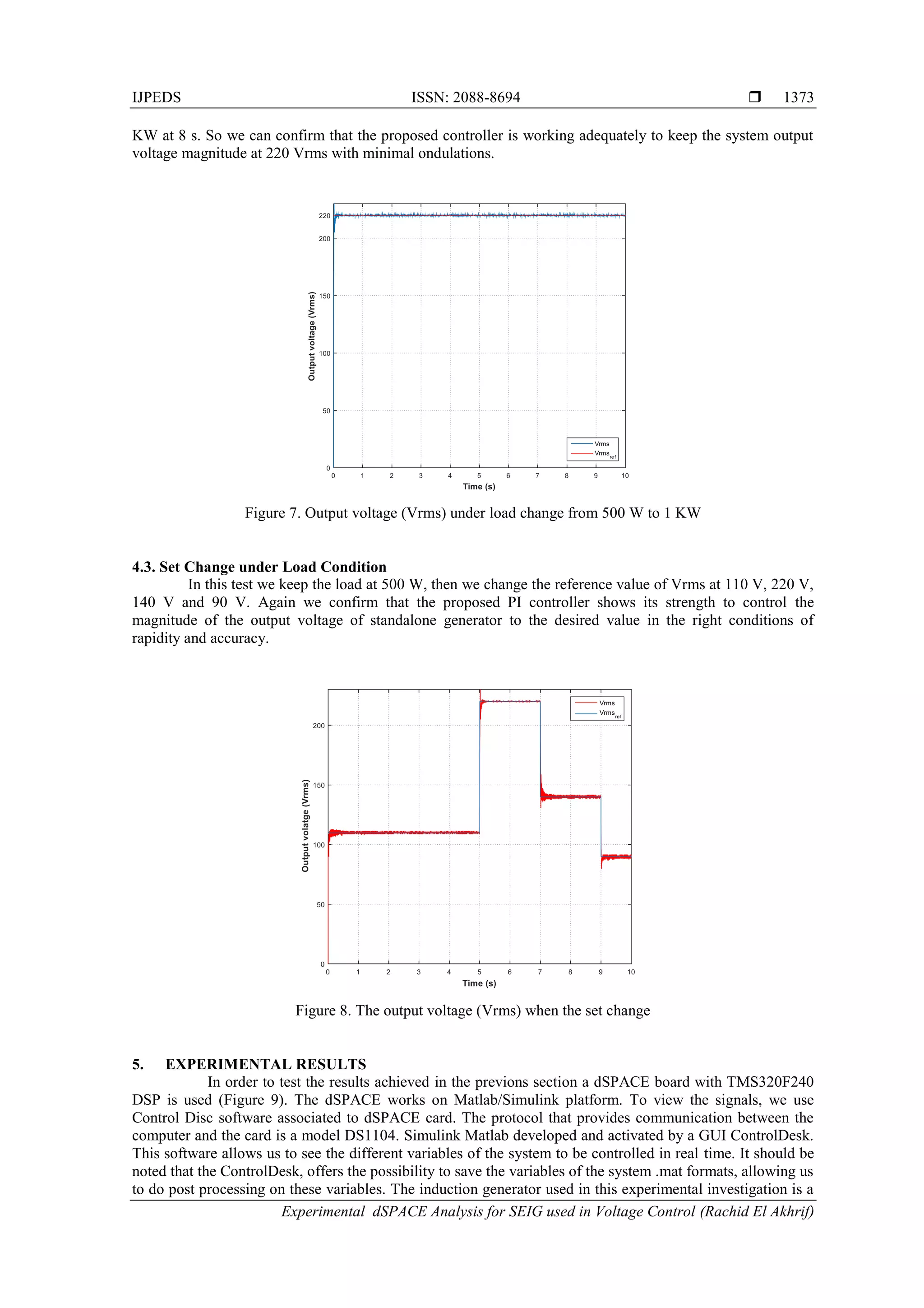
6. CONCLUSION
In This study we are investigating a three-phase system powered by three-phase voltage inverter
which uses as an energy source asynchronous generator running in standalone mode, the control system
proposed is based on a simple PI controller. In this issue, we evaluated the performance of the voltage
regulation system under several constraints, so we analyse the effect of the variation of the wind speed
represented here by the change of the rotor speed and also the effect of the variation the AC load. The graphs
obtained in the simulation confirms that the controller shows its robustness and strenght characteristics in
keeping the output voltage at the desired value to feed the power for a variety of loads. The dSPACE
experimental result was presented to confirm the simulation results obtained above. Our next study is to
compare the proposed controller performance with a fuzzy logic controller under the same experimental
conditions.
APPENDIX
Table 3. Induction Generator Parameters
Rated power 3KW
Voltage 380V Y
Frequency 50 Hz
Pair pole 2
Rated speed 1400 rpm
Stator resistance 1.7 Ω
Rotor resistance 2.68 Ω
Inductance stator 229 mH
Inductance rotor 229 mH
Mutual inductance 217 mH
Moment of lnertia 0.046 kg.m2
Filter inductance 33,9 mH
Filter capacitance 310 mF
REFERENCES
[1] Omid Alavi, Behzad Vatandoust “Economic Selection of Generators for a Wind Farm”, Indonesian Journal of
Electrical Engineering and Informatics (IJEEI), Vol. 3, No. 3, September 2015, pp. 121-128.
[2] A. Nesba, R. Ibtiouen, S. Mekhtoub, O. Touhami, N. Takorabet, “ Rectified Self-Excited Induction Generator as
Regulated DC Power Supply for Hybrid Renewable Energy Systems”, WSEAS Trans. on Circuits and Systems,
Issue 11, Vol. 4, November 2005, pp. 1457–1463.](https://image.slidesharecdn.com/8381-9537-1-pb-210608022759/75/Experimental-dSPACE-Analysis-for-Self-excited-Induction-Generator-Used-in-Voltage-Control-12-2048.jpg)
![ ISSN: 2088-8694
IJPEDS Vol. 8, No. 3, September 2017 : 1368–1380
1380
[3] M. Sasikumar, R. Madhusudhanan, S. Chenthur Pandian “Modeling and Analysis of Cascaded VSI for Wind
Driven Isolated Squirrel Cage Induction Generators”, IEEE Recent Advance in Space Technology and climate
Chane, pp. 424-429, 2010.
[4] J. Dixon, L. Moran “Multilevel inverter, based on multi-stage connection of three-level converters scaled in power
of three”, IEEE 28th Annual Conference of the Industrial Electronics Society, pp. 886-891, 2002.
[5] Ashwani Kumar Sharma “Study of Wind Turbine based SEIG under Balanced/Unbalanced Loads and Excitation”,
International Journal of Electrical and Computer Engineering (IJECE), Vol 2 No 3, 2012 pages 353-370.
[6] A. Varschavsky, J. Dixon, M. Rotella, L. Moran “Cascaded nine-level inverter for hybrid-series active power filter,
using industrial controller”, IEEE Transactions on Industrial Electronics, Vol. 57, pp. 2761-2767, 2010.
[7] F. P. Zeng, G. H. Tan, J. Z. Wang, Y. C. Ji “Novel single-phase-five-level voltage-source inverter for the shunt
active power filter”, IET Power Electronics, Vol. 3, pp. 480-489, 2010.
[8] X. Q. Guo, W. Y. Wu, H. R. Gu “Modeling and simulation of direct output current control for LCL-interfaced grid-
connected inverters with parallel passive damping”, Simulation Modelling Practice and Theory, Vol. 18, pp. 946-
956, 2010.
[9] A. F. Zobaa “Voltage harmonic reduction for randomly time-varying source characteristics and voltage harmonics”,
IEEE Transactions on Power Delivery, Vol. 21, pp. 816-822, 2006.
[10] O.O. Mengi, I.H. Altas “Fuzzy logic control for a wind/battery renewable energy production system”, Turkish
Journal of Electrical Engineering & Computer Sciences, Vol. 20, pp. 187-206, 2012.
[11] M. Barara, A. Chimezie, N. Al Sayari, A. Beig, K. H. Alhosani, A. Abbou, M. Akherraz “Hardware
Implementation of Voltage Control for Self Excited Induction Generator Used in Small Power Generation”,
International Review of Electrical Engineering (I.R.E.E.), Vol. 10, pp. 553-560, 2015.
[12] G. H. Zeng, T. W. Rasmussen “Design of current-controller with PR-regulator for LCL- filter based grid-connected
converter”, 2nd IEEE International Symposium on Power Electronics for Distributed Generation Systems, pp. 490-
494, 2010.
[13] M. Bašić, D. Vukadinović, M. Polić “Fuzzy DC-Voltage Controller for a Vector Controlled Stand-Alone Induction
Generator”, International Journal Of Circuits, Systems And Signal Processing, Issue 3, Volume 7, 2013.
[14] M. Barara, A. Abbou, M. Akherraz, A. Bennaser, D. Taibi, ’’Comparative Study of PI and Fuzzy DC Voltage
Control for a Wind Energy Conversion System’’, International Review on Modelling and Simulations
(I.RE.MO.S.), Vol. 6, N. 2 April 2013.
[15] T. L. TIANG, D. ISHAK, “Modeling and simulation of deadbeat-based PI controller in a single-phase H-bridge
inverter for stand-alone applications”, Turkish Journal of Electrical Engineering & Computer Sciences, pp. 43-56,
2014.
[16] A. W. Leedy, R. M. Nelms “A general method used to conduct a harmonic analysis on carrier-based pulse width
modulation inverters", Simulation, Vol. 87, pp. 205-220, 2010.
[17] R. El Akhrif, A. Abbou, M. Barara, Y. Majdoub “Modeling and simulation for a three-phase voltage source inverter
fed by a self-excited induction generator ”, IEEE 2016 7th International Renewable Energy congress, 2016.](https://image.slidesharecdn.com/8381-9537-1-pb-210608022759/75/Experimental-dSPACE-Analysis-for-Self-excited-Induction-Generator-Used-in-Voltage-Control-13-2048.jpg)


![4.[14 24]modeling, analysis and control of hexagram inverter for three- phase...](https://cdn.slidesharecdn.com/ss_thumbnails/4-14-24modelinganalysisandcontrolofhexagraminverterforthree-phaseinductionmotordrive-111203184955-phpapp02-thumbnail.jpg?width=640&height=640&fit=bounds)


