
Recommended
More Related Content
What's hot
Viewers also liked
Viewers also liked (17)
Similar to Et201 eoc1
Similar to Et201 eoc1 (20)
Recently uploaded
Recently uploaded (20)
Et201 eoc1
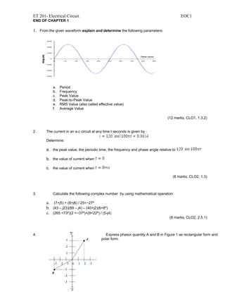
- 1. ET 201- Electrical Circuit EOC1 END OF CHAPTER 1 1. From the given waveform explain and determine the following parameters: a. Period b. Frequency c. Peak Value d. Peak-to-Peak Value e. RMS Value (also called effective value) f. Average Value (12 marks, CLO1, 1.3.2) 2. The current in an a.c circuit at any time t seconds is given by : Determine: a. the peak value, the periodic time, the frequency and phase angle relative to b. the value of current when c. the value of current when (8 marks, CLO2, 1.3) 3. Calculate the following complex number by using mathematical operation a. (7+j5) + (8+j6) / 25<−27º b. (43 – j23)(89 – j4) – (40+j2)(6<8º) c. (265 <73º)(2 <−37º)+(9<22º) / (5-j4) (6 marks, CLO2, 2.5.1) 4. Express phasor quantity A and B in Figure 1 as rectangular form and polar form.
- 2. ET 201- Electrical Circuit EOC1 Figure 1 (4 marks, CLO1, 2.3.1) 5. a. Sketch the phasor diagram and sinusoidal waveform to show the relationship between voltage and current in purely resistive, capacitive and inductive circuit. b. State the relationship between R, XL and XC with respect to frequency (10 marks, CLO1, 3.1) 6. Calculate IT , IR , IL , IC ,VT , VR , VL , VC , XC and XL a. 10 Vrms ,1 khz 1kΩ 0.1 H 1.2 μF Figure 2 b. 1 KΩ 150 mH 0.3 μF 12 Vrms, 1.2 khz Figure 3 (20 marks, CLO2, 3.4)
- 3. ET 201- Electrical Circuit EOC1