Downloaded 248 times
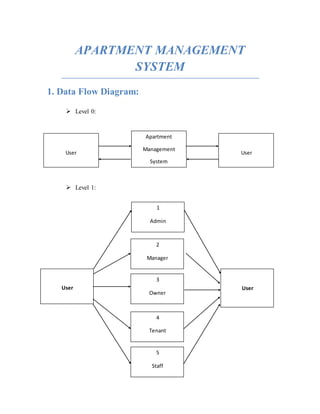
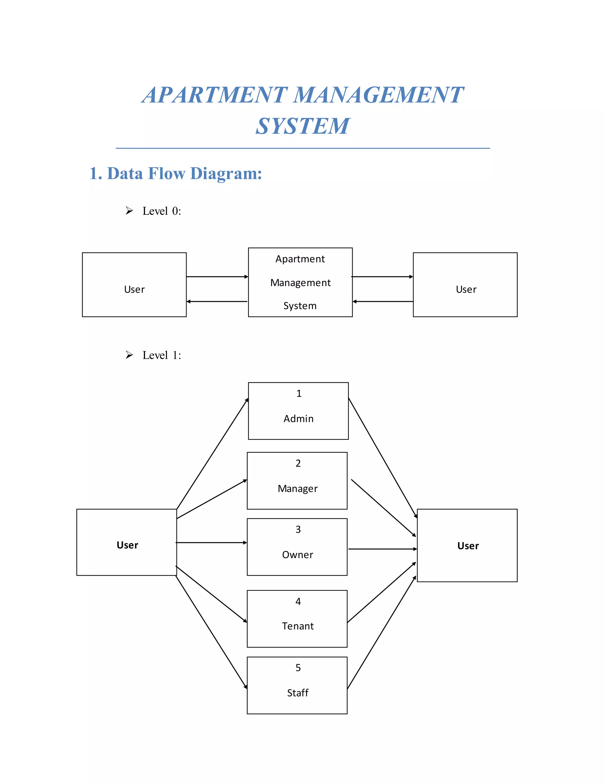
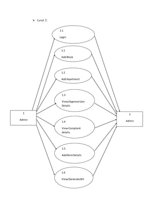
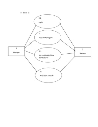

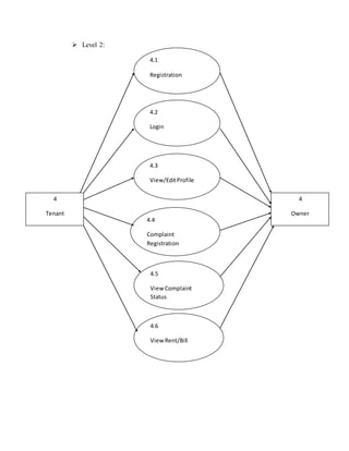
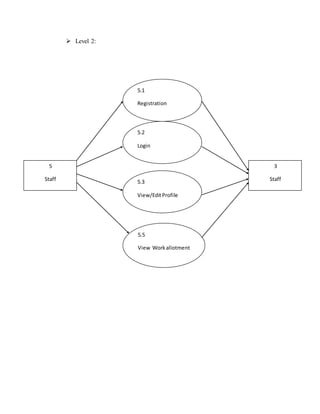
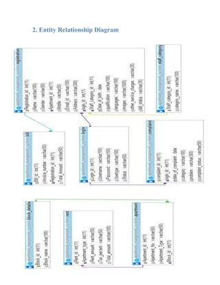
This document outlines the data flow and entity relationship diagrams for an apartment management system. The data flow diagram shows information flowing between users at different levels, with level 1 showing the major system processes and level 2 breaking these down further. The entity relationship diagram models the key entities (e.g. users, apartments, rent details) and their relationships.