SlideShare a Scribd company logo
Printed by Jouve, 75001 PARIS (FR)
(19)EP1917898A1
(11) EP 1 917 898 A1
(12) EUROPEAN PATENT APPLICATION
(43) Date of publication:
07.05.2008 Bulletin 2008/19
(21) Application number: 07117884.2
(22) Date of filing: 04.10.2007
(51) Int Cl.:
A47L 11/30 (2006.01)
(84) Designated Contracting States:
AT BE BG CH CY CZ DE DK EE ES FI FR GB GR
HU IE IS IT LI LT LU LV MC MT NL PL PT RO SE
SI SK TR
Designated Extension States:
AL BA HR MK RS
(30) Priority: 03.11.2006 IT PN20060086
(71) Applicant: CFM Nilfisk-Advance S.p.A.
20121 Milano (IT)
(72) Inventors:
• COCCAPANI, Sergio
43011, BUSSETO (Parma) (IT)
• MARCHETTI, Filippo
29019, SAN GIORGIO (Piacenza) (IT)
(74) Representative: Gonella, Mario et al
Propria S.r.l.
P.O. Box 365
Via della Colonna, 35
33170 Pordenone (IT)
(54) Floor cleaning machine
(57) The present invention refers to a floor cleaning
machine comprising brush means (2) adapted to scrub
the floor (4) with a cleaning, i.e. detergent liquid in view
of removing soil and dirt therefrom, and a wiping device
(3) adapted to scrape the floor (4) in order to remove the
dirty cleaning liquid therefrom; the wiping device (3) com-
prises a front flap (5) and a rear flap (6) adapted to elas-
tically and slidably engage the floor (4) so as to define a
suction chamber (7) therebetween, wherein said suction
chamber is fluidly connected to suction means (8), and
wherein said front flap (5) is provided with a plurality of
indentations (9) of a reduced cross-sectional size to con-
vey the dirty cleaning liquid into the suction chamber (7);
at least a portion of the front flap (5) is provided in the
form of a tab (10) that is associated to the same front flap
(5) viaa ruptureedge (11),wherein such tab (10) is adapt-
ed to be removed so as to form a breach or passageway
(12) having a broader cross-sectional size in the front
flap (5) in order to reduce the speed of the air entering
the suction chamber (7) and, as a result, the related suc-
tion noise. A method for manufacturing a scraping flap
is also provided.
EP 1 917 898 A1
2
5
10
15
20
25
30
35
40
45
50
55
Description
[0001] The present invention refers to a floor cleaning
machine.
[0002] Floor cleaning, i.e. washing-drying machines
usually comprise a brushing device with water and/or liq-
uid detergent dispensing provision to wash the floor, as
well as a wiping device to remove the dirty liquid from
the floor and dry up the latter.
[0003] Such wiping device has the purpose of scraping
and vacuuming the floor behind the brushing device, in
order to remove the dirty liquid therefrom by taking it in
through suction means, which it is appropriately connect-
ed with.
[0004] The wipingdeviceisusuallycomprised ofasup-
port, to which there are mounted two flaps (or wiping
blades, as they are generally referred to in the art) that
are made of a rubber-based or rubber-like material to be
able to elastically and slidably engage the floor to be
cleaned. These flaps, i.e. a front one - facing forwards,
i.e. in the forward direction of movement of the machine
- and a rear one, are biased, i.e. pressed against the floor
so as to substantially act as sealing gaskets and delim-
itate a suction chamber therebetween, which is connect-
ed to the suction or vacuuming means via a conduit. The
rear flap has usually a larger thickness and is made of a
softer material featuring a greater resistance to water and
detergent liquid, since it must perform as to be able to
retain the dirty washing liquid inside the chamber for it to
be effectively removed by suction.
[0005] The front flap has the task of conveying the liq-
uid into the suction chamber and, to this purpose, it is in
fact provided with a plurality of indentations or cuts made
along the floor scraping border, i.e. the border in contact
with the floor, so as to allow the washing liquid to seep
into and enter the suction chamber. The provision of such
indentations or cuts has the effect of reducing the nega-
tive pressure being created by the suction means inside
the chamber, but allows for a correct removal of the air-
liquid mixture by suction.
[0006] While seeping through such indentations or
cuts, the air and the liquid generate some noise.
[0007] Now, the higher is the speed of the air being
sucked in through the indentations and, as a result, the
greater is the negative pressure inside the suction cham-
ber, the higher is the noise generated.
[0008] Generally, however, the greater is the negative
pressure that is created inside the suction chamber, the
better is the ability of the liquid to be effectively removed
from the floor by suction.
[0009] By increasing the overall dimensions of the in-
dentations or cuts in the front flap, i.e. by providing ap-
ertures with a broader cross-section, the negative pres-
sure created inside the suction chamber and, as a result,
the overall suction capacity are reduced, but the effect
is on the other hand obtained in this way of drastically
reducing the noise generated by the air being sucked in
and passing through the indentations.
[0010] When treating some kinds of floors (typically
those paved with tiles and featuring fissures and junc-
tures), the negative pressure shall necessarily be high
enough so as to allow the liquid to be correctly and ef-
fectively removed by suction, even if this involves - as a
consequence - a greater noise emission, which people
are anyway willing to accept since the priority - in these
cases - lies in ensuring the highest possible suction ca-
pacity.
[0011] On other kinds of floors (e.g. linoleum-covered
floors, marble floors, and the like), the suction capacity
may be equally effective even with a lower negative pres-
sure prevailing inside the suction chamber and, there-
fore, under a reduced emission of noise.
[0012] In certain places and environments (e.g. indus-
trial premises, supermarkets, gyms, and the like) the pre-
vailing priority lies in having or obtaining a great suction
capacity at the expense of a considerable extent of noise
emitted.
[0013] In other places (such as hospitals, schools, and
the like), people are rather willing to accept a relatively
lower suction effectiveness, since the priority lies in this
case in ensuring as low as possible an emission of noise.
[0014] Floor-cleaning equipment manufacturers cur-
rently provide front flaps featuring either indentations of
a reducedcross-section size, so as to ensure a maximum
extent of suction capacity, or larger-sized indentations
that favour a low emission of noise, while giving up part
of the suction effectiveness.
[0015] It has however been found that, in the case of
front flaps provided with indentations with a reduced
cross-section size (i.e. aimed at obtaining a maximum
extent of negative pressure created inside the suction
chamber), the final equipment users themselves tend to
manually provide - using scissors or similar tools - larger-
sized apertures in view of reducing the noise level of the
machines.
[0016] It may of course be quite readily appreciated
that such tampering is quite difficult a job, and further
requires a lot of time to be completed, since it involves
the front flap to be removed from the wiping device, the
additional aperture or apertures to be cut thereinto, and
finally the so re-processed front flap to be assembled
again on to the wiping device.
[0017] It can furtherbereadily appreciated that - during
the process of making such additional apertures in the
front flap, i.e. a process that largely depends on the skills
and the experience of the user carrying it out - the front
flap may itself be caused - owing to errors in tampering
therewith or similar problems - to undergo tears and sim-
ilar damages that might even impair the good state and
operativeness thereof, up to making it necessary for it to
be totally replaced.
[0018] It is therefore a main object of the present in-
vention to provide a floor-cleaning machine that is pro-
vided with a front flap that does away with the afore-cited
drawbacks of prior-art equipment.
[0019] Within this general object, it is a purpose of the
1 2
EP 1 917 898 A1
3
5
10
15
20
25
30
35
40
45
50
55
present invention to provide a front flap that is more ver-
satile and practical than the front flaps being currently
available on the market, and is capable of being used so
as to selectively favour the suction capacity or a reduced
noise level of the machine, in accordance with the re-
quirements of the user.
[0020] A further purpose of the present invention is to
provide a flap that is simple in its construction and reliable
in use, as well as capable of being manufactured at fully
competitive costs.
[0021] According to the present invention, these aims,
along with further ones that will become apparent from
the following disclosure, are reached in a floor-cleaning
machine and a method for providing a flap that incorpo-
rate the features and characteristics as defined and re-
cited in claim 1 et seq. appended hereto.
[0022] Advantages and features of the present inven-
tion will anyway be more readily understood from the
description of a preferred, although not sole embodiment
that is given below by way of non-limiting example with
reference to the accompanying drawings, in which:
- Figure 1 is a perspective front view of the floor-clean-
ing machine according to the present invention;
- Figure 2 is a perspective rear view of the floor-clean-
ing machine according to the present invention;
- Figure 3 is a perspective bottom view of the wiping
device and the related support;
- Figure 4 is an enlarged, side cross-sectional view of
the wiping device;
- Figure 5 is an exploded view of the wiping device;
- Figure 6 is a perspective front view of the wiping
device and the front flap with both associated and
removed tabs;
- Figure 7 is a front view of the front flap in its integral
state and with both associated and removed tabs.
[0023] With reference to the above-noted Figures, the
floor cleaning machine according to the present inven-
tion, as generally indicated with the reference numeral 1
there, comprises brush means 2 adapted to scrub the
floor 4 with a cleaning, i.e. detergent liquid in view of
removing soil and dirt therefrom, and a wiping device 3
adapted to scrape the floor 4 in order to remove the dirty
cleaning liquid therefrom.
[0024] The wiping device 3 comprises a front flap 5
and a rear flap 6 adapted to elastically and slidably en-
gage the floor 4 to define a suction chamber 7 therebe-
tween, wherein said suction chamber is fluidly connected
to suction means 8. In addition, the front flap 5 is provided
with a plurality of indentations 9 of a reduced cross-sec-
tional size to convey the dirty cleaning liquid into the suc-
tion chamber 7.
[0025] Advantageously, at least a portion of the front
flap 5 is provided in the form of a tab 10 that is associated
to the same front flap via a rupture edge 11. Such tab 10
is adapted to be removed so as to form a breach or pas-
sageway 12 having a broader cross-sectional size in the
front flap 5 in order to reduce the speed of the air entering
the suction chamber 7 and, as a result, the related suction
noise.
[0026] The floor cleaning machine comprises a frame
or chassis 13 with a housing body 14 rising thereabove
for the various component parts of the machine to be
accommodated therein. The brushing means 2 may for
instance comprise a pair of rotary brushes located at a
front end portion of the chassis 13 of the machine along
with appropriate motor means (not shown in the draw-
ings) to rotatably drive said brushes. In addition, the floor
cleaning machine comprises a reservoir for storing a liq-
uid detergent which, by means of a pump, is delivered
to the brushes so that the same brushes - as driven ro-
tatably by said motor means - rub the liquid detergent
onto the floor 4 to remove soil and dirt therefrom. For the
resulting dirty liquid detergent to be then removed from
the floor 4, the machine is provided with a wiping device
3, which is provided on the rear end portion of the chassis
13 and connected to suction means 8.The suctionmeans
8 comprise a suction pump or compressor located within
the housing body 14 and connected - via appropriate
conduits - with the wiping device 3 and a recovery con-
tainer provided in the same housing body 14. When the
pump is operated, the dirty detergent liquid is taken in by
suction through the wiping device 3, which trails grazingly
along the floor 4 behind the brushes, to be eventually
sent to the recovery container.
[0027] The wiping device 3 comprises a support mem-
ber 16 provided in an arcuate shape, which defines a
cavity 17 that is open towards the floor 4. In practice,
suchsupportmember 16hasacross-section intheshape
of a U turned downwards, which defines a delimited
space facing towards the floor along which the wiping
device 3 is due to sweep.
[0028] The suction means 8 are connected to the wip-
ing device 3 via a suction conduit 18 that fluidly commu-
nicates with the cavity 17 of the support member 16; in
particular, the suction conduit 18 is connected to a middle
portion of the support member 16. The support member
16 defines an arcuate front surface 19 facing forwards,
i.e.inthe direction offorwardmovement ofthe floor clean-
ing machine, and an arcuate rear surface 20, which com-
bine to define the space of the cavity 17 connected to
the suction conduit 18.
[0029] A front scraping flap 5 and a rear scraping flap
6 are associated to the arcuate front surface 19 and the
arcuate rear surface 20 of the support member 16, re-
spectively, so as to wipe, i.e. scrape the wet floor and
remove the dirty liquid therefrom.
[0030] The flaps 5, 6 (which are commonly referred to
as the wiper blades in the art) are generally made of a
3 4
EP 1 917 898 A1
4
5
10
15
20
25
30
35
40
45
50
55
suitable plastic-rubber material, such as NR, SBR, neo-
prene, polyurethane, just to name a few, are intended to
elastically and slidably engage the floor 4 and define a
suction chamber 7 therebetween, which is connected to
the suction conduit 18 via the support member 16. In
practice, such flaps 5, 6, that are biased, i.e. pressed into
contact with the floor, perform as gaskets adhering
against the floor to create the suction chamber 7. The
front flap 5 is provided with a sequence of indentations
or cuts 9 of a reduced cross-sectional size along the bor-
der of the flap 5 due to engage the floor, so as to enable
the mixture formed of air and dirty cleaning liquid to seep
therethrough into the suction chamber 7, thereby remov-
ing the liquid from the floor. Such indentations 9, there-
fore, have the purpose of conveying the dirty cleaning
liquid into the space comprised between the flaps, where
- owing to the negative pressure created by the suction
means 8 - the liquid is removed from the floor by suction.
[0031] The arcuate shape, featuring a concavity ori-
ented in the direction of forward movement of the floor
cleaning machine, of the support member 16 and, as a
result, of the suction chamber 7 being defined between
the two flaps 5, 6, enables the liquid to be directed to-
wards the middle portion of the cavity 17 of the support
member 16, where the suction conduit 18 is provided. A
pair of wheels 21 are provided to prevent the support
member 16, which is usually made of a rigid material,
e.g. metal, from being dragged along on the floor when
the floor cleaning machine is being used. A pair of side
castors 22 are provided to prevent the side end portions
ofthesupportmember16 from scouring againstthelower
portion of a wall when the floor cleaning machine is used
to wash a portion of floor lying close to such wall.
[0032] The flaps 5, 6 feature a sequence of perfora-
tions 23 provided centrally all along the flaps and adapted
to engage corresponding projections 24 provided on the
front surface 19 and the rear surface 20 of the support
member 16. Clamping bands 25 are adapted to snap
onto such projections 24 so as to removably fasten the
flaps 5, 6 to the support member 16 and enable them to
be quickly and conveniently removed for replacement or
similar requirements.
[0033] The wiping device 3 is attached to the floor
cleaning machine by means of an upright pin 26 associ-
ated on to the chassis 13, to which there is secured a
first bracket 27 adapted to rotate about such pin 26 along
a horizontal plane. The support member 16 is secured
to a second bracket 28 hinged on to the first bracket 27
along a horizontal axis, about which it is free to swing.
Spring means 29 bias the second bracket 27 towards the
floor so as to ensure that the flaps 5, 6 keep elastically
engaging the floor in an adequate manner to effectively
create the afore-mentioned suction chamber 7 therebe-
tween.
[0034] The front flap 5 advantageously comprises at
least a rupture portion - situated close to or along the
floor-scraping border thereof - that is adapted to be torn
off by a user in view of creating a breach or passageway
12 in the same flap having a broader cross-sectional size
than the indentations 9. The thus created gap or breach
12 enables the overall size of the apertures in the front
flap 5 to be increased and, as a result, the negative pres-
sure prevailing inside the suction chamber 7 and, there-
fore, the speed of the air seeping into the chamber to be
reduced accordingly, with the result of a drastically re-
duced noise generated by the suction effect.
[0035] The rupture portion to be torn off the front flap
in view of forming a related breach or gap consists of a
tab 10 associated to the front flap 5 via a tear-off edge
11 that enables the tab 10 to be removed by simply tear-
ing it off.
[0036] Mostobviously, said rupture edge 11 will be suf-
ficiently strong and resistant as to prevent the tab 10 from
breaking off accidentally during normal operation of the
wiping device 3, in the case that the tab 10 is preferably
left in position in view of obtaining a maximum extent of
suction capacity, regardless of the noise.
[0037] In the opposite case, i.e. when particular low-
noise requirements are to be complied with, all it takes
is tearing the tab 10 off to reduce the suction noise of the
machine accordingly.
[0038] The rupture edge 11 may be obtained by for
example making a sequence of microperforations along
a contour delimiting the portion of front flap 5 to be re-
moved to create the breach or gap 12, wherein it will be
readily appreciated that a number of other techniques
may be used to obtain the same result, such as by prop-
erly pressing or constricting the front flap 5 along the
contour of the portion to be torn off, so as to reduce the
tensile, i.e.rupture strength oftheflap along said contour.
[0039] It is contemplated that the indentations 9 having
a reduced cross-sectional size be provided along both
longitudinal borders of the front flap 5, so that no need
will exist for the front flap 5 to be strictly applied on to the
support member 16 in a preferential way, direction or
position. Furthermore, when a longitudinal border even-
tually wears out to the point that the same operating ef-
fectiveness of the machine is impaired, all it takes is dis-
assembling the flap 5, turning it upside down and fasten-
ing it again on to the related support member 16 so that
the still intact border thereof is now facing towards the
floor.
[0040] To the same purpose, even the tear-off tab 10
is provided along both longitudinal borders of the front
flap 5.
[0041] In particular, the tear-off tabs 10 and the related
rupture edges 11 are provided close to the middle portion
of the front flap 5 along both longitudinal borders thereof.
[0042] Fully apparent from the above description is
therefore the ability of the present invention to effectively
reach the afore-cited aims and advantages by providing
a floor cleaning machine provided with a front flap that
is particularly simple from a construction point of view,
as well as reliable in use and requiring just a simple, quick
handling in view of providing a larger-sized breach or gap
in the same flap.
5 6
EP 1 917 898 A1
5
5
10
15
20
25
30
35
40
45
50
55
[0043] It will be readily appreciated that the flap ac-
cording to the present invention may be embodied in a
number of manners differing from the above-described
one, and may be the subject of a number of further mod-
ifications, without departing from the scope of the present
invention. Moreover, all afore-described details may be
replaced by technically equivalent elements.
[0044] It should finally be noticed that the materials
used to manufacture the flap of the present invention, as
well as the shapes and the sizing of the individual com-
ponent parts thereof, may each time be selected so as
to more appropriately meet the particular requirements
or suit the particular application, again without departing
from the scope of the present invention.
Claims
1. Floor cleaning machine comprising brush means (2)
adapted to scrub the floor (4) with a cleaning, i.e.
detergent liquid in view of removing soil and dirt
therefrom, and a wiping device (3) adapted to scrape
the floor (4) in order to remove the dirty cleaning
liquid therefrom, said wiping device (3) comprising
afront flap(5)andarearflap(6)adapted toelastically
and slidably engage the floor (4) so as to define a
suction chamber (7) therebetween, wherein said
suction chamber is fluidly connected to suction
means (8), and wherein said front flap (5) is provided
with a plurality of indentations (9) of a reduced cross-
sectional size to convey the dirty cleaning liquid into
the suction chamber (7), characterized in that at
least a portion of the front flap (5) is provided in the
form of a tab (10) that is associated to the same front
flap (5) via a rupture edge (11), wherein such tab
(10) is adapted to be removed so as to form a breach
or passageway (12) having a broader cross-section-
al size in the frontflap (5) in order to reduce the speed
of the air entering the suction chamber (7) and, as a
result, the related suction noise.
2. Method formanufacturing a scraping flap fora wiping
device of a floor cleaning machine, said wiping de-
vice (3) comprising a front scraping flap (5) and a
rear scraping flap (6) adapted to elastically and sli-
dably engage the floor (4) so as to define a suction
chamber (7) fluidly connected to suction means (8)
therebetween, wherein said method comprises the
steps of:
-providing a sheetofflexible water-resistantma-
terial,
- cuttinganelongated longitudinalstripfrom said
sheet,
- making a plurality of indentations (9) of a small
cross-sectional size along at least one of the lon-
gitudinal borders of such strip,
characterized in that it further comprises the step
of:
- providing a rupture contour (11) delimiting a
tab (10) in said strip in order to enable said tab
(10) to be simply torn off said strip in view of
creating a breach or gap (12) having a broader
cross-sectional size to the purpose of reducing
thespeedoftheairenteringthesuctionchamber
(7) and, as a result, the related suction noise.
3. Scraping flap for the wiping device of a floor cleaning
machine comprising a plurality of indentations (9) of
reduced cross-sectional size, characterized in that
at least a portion of the front flap (5) is provided in
the form of a tab (10) that is associated to the same
front flap (5) via a rupture edge (11), wherein such
tab (10) is adapted to be removed so as to form a
breach or passageway (12) having a broader cross-
sectional size in the same front flap (5).
7 8
EP 1 917 898 A1
6
EP 1 917 898 A1
7
EP 1 917 898 A1
8
EP 1 917 898 A1
9
EP 1 917 898 A1
10
EP 1 917 898 A1
11
EP 1 917 898 A1
12

More Related Content

Viewers also liked

Viewers also liked (9)

Brand analysis project: OG&E
Brand analysis project: OG&EBrand analysis project: OG&E
Brand analysis project: OG&E
 
Us4989289
Us4989289Us4989289
Us4989289
 
Us8302240
Us8302240Us8302240
Us8302240
 
Ep0314509 a2
Ep0314509 a2Ep0314509 a2
Ep0314509 a2
 
women in stem higher education
women in stem higher educationwomen in stem higher education
women in stem higher education
 
Us6647585
Us6647585Us6647585
Us6647585
 
Kti irma yulistiani
Kti irma yulistianiKti irma yulistiani
Kti irma yulistiani
 
course book community nursing
course book community nursingcourse book community nursing
course book community nursing
 
What is Zika Virus?
What is Zika Virus?What is Zika Virus?
What is Zika Virus?
 

Similar to Ep1917898 a1

Similar to Ep1917898 a1 (20)

5771 5775.output
5771 5775.output5771 5775.output
5771 5775.output
 
5771 5775.output
5771 5775.output5771 5775.output
5771 5775.output
 
Us7476267
Us7476267Us7476267
Us7476267
 
US20140138867 (2)
US20140138867 (2)US20140138867 (2)
US20140138867 (2)
 
Us20060000040 a1
Us20060000040 a1Us20060000040 a1
Us20060000040 a1
 
Us20070050938 a1
Us20070050938 a1Us20070050938 a1
Us20070050938 a1
 
Us7329295
Us7329295Us7329295
Us7329295
 
5521 5525.output
5521 5525.output5521 5525.output
5521 5525.output
 
Us7303613
Us7303613Us7303613
Us7303613
 
Us20100229315 a1
Us20100229315 a1Us20100229315 a1
Us20100229315 a1
 
Patent_(FK)_EP 2 843 177 B1
Patent_(FK)_EP 2 843 177 B1Patent_(FK)_EP 2 843 177 B1
Patent_(FK)_EP 2 843 177 B1
 
IRJET- Design, Manufacturing and Testing of Open-Circuit Subsonic Wind Tunnel...
IRJET- Design, Manufacturing and Testing of Open-Circuit Subsonic Wind Tunnel...IRJET- Design, Manufacturing and Testing of Open-Circuit Subsonic Wind Tunnel...
IRJET- Design, Manufacturing and Testing of Open-Circuit Subsonic Wind Tunnel...
 
Us8296901
Us8296901Us8296901
Us8296901
 
Defect reduction
Defect reduction Defect reduction
Defect reduction
 
66 alan shibata - 6557987 - co-extruded tubing for an off-axis ink delivery...
66   alan shibata - 6557987 - co-extruded tubing for an off-axis ink delivery...66   alan shibata - 6557987 - co-extruded tubing for an off-axis ink delivery...
66 alan shibata - 6557987 - co-extruded tubing for an off-axis ink delivery...
 
Pipeline Strainers - A Tutorial
Pipeline Strainers - A TutorialPipeline Strainers - A Tutorial
Pipeline Strainers - A Tutorial
 
Us7571509
Us7571509Us7571509
Us7571509
 
Project By Rcdohare& Miss Kakoli Shaw
Project By Rcdohare& Miss Kakoli ShawProject By Rcdohare& Miss Kakoli Shaw
Project By Rcdohare& Miss Kakoli Shaw
 
Industrial flooring by tremix vacuum system
Industrial flooring by tremix vacuum systemIndustrial flooring by tremix vacuum system
Industrial flooring by tremix vacuum system
 
S3 End Of Chapter - Loss of a Trap Seal
S3 End Of Chapter - Loss of a Trap SealS3 End Of Chapter - Loss of a Trap Seal
S3 End Of Chapter - Loss of a Trap Seal
 

Recently uploaded

Claire's designing portfolio presentation
Claire's designing portfolio presentationClaire's designing portfolio presentation
Claire's designing portfolio presentationssuser8fae18
 
BIT- Pinal .H. Prajapati Graphic Designer
BIT- Pinal .H. Prajapati  Graphic DesignerBIT- Pinal .H. Prajapati  Graphic Designer
BIT- Pinal .H. Prajapati Graphic Designerbitwgin12
 
Spring 2024 wkrm_Enhancing Campus Mobility.pdf
Spring 2024 wkrm_Enhancing Campus Mobility.pdfSpring 2024 wkrm_Enhancing Campus Mobility.pdf
Spring 2024 wkrm_Enhancing Campus Mobility.pdfJon Freach
 
CA OFFICE office office office _VIEWS.pdf
CA OFFICE office office office _VIEWS.pdfCA OFFICE office office office _VIEWS.pdf
CA OFFICE office office office _VIEWS.pdfSudhanshuMandlik
 
The Evolution of Fashion Trends: History to Fashion
The Evolution of Fashion Trends: History to FashionThe Evolution of Fashion Trends: History to Fashion
The Evolution of Fashion Trends: History to FashionPixel poets
 
FW25-26 Fashion Key Items Trend Book Peclers Paris
FW25-26 Fashion Key Items Trend Book Peclers ParisFW25-26 Fashion Key Items Trend Book Peclers Paris
FW25-26 Fashion Key Items Trend Book Peclers ParisPeclers Paris
 
Heuristic Evaluation of System & Application
Heuristic Evaluation of System & ApplicationHeuristic Evaluation of System & Application
Heuristic Evaluation of System & ApplicationJaime Brown
 
Research about Venice ppt for grade 6f anas
Research about Venice ppt for grade 6f anasResearch about Venice ppt for grade 6f anas
Research about Venice ppt for grade 6f anasanasabutalha2013
 
National-Learning-Camp 2024 deped....pptx
National-Learning-Camp 2024 deped....pptxNational-Learning-Camp 2024 deped....pptx
National-Learning-Camp 2024 deped....pptxAlecAnidul
 
Extended Reality(XR) Development in immersive design
Extended Reality(XR) Development in immersive designExtended Reality(XR) Development in immersive design
Extended Reality(XR) Development in immersive designGOWSIKRAJA PALANISAMY
 
Design lessons from Singapore | Volume 3
Design lessons from Singapore | Volume 3Design lessons from Singapore | Volume 3
Design lessons from Singapore | Volume 3Remy Rey De Barros
 
Common Designing Mistakes and How to avoid them
Common Designing Mistakes and How to avoid themCommon Designing Mistakes and How to avoid them
Common Designing Mistakes and How to avoid themmadhavlakhanpal29
 
Pitch Presentation for Service Design in Technology
Pitch Presentation for Service Design in TechnologyPitch Presentation for Service Design in Technology
Pitch Presentation for Service Design in TechnologyJaime Brown
 
The Design Code Google Developer Student Club.pptx
The Design Code Google Developer Student Club.pptxThe Design Code Google Developer Student Club.pptx
The Design Code Google Developer Student Club.pptxadityakushalsaha
 
Dos And Dont's Of Logo Design For 2024..
Dos And Dont's Of Logo Design For 2024..Dos And Dont's Of Logo Design For 2024..
Dos And Dont's Of Logo Design For 2024..GB Logo Design
 
Art Nouveau Movement Presentation for Art History.
Art Nouveau Movement Presentation for Art History.Art Nouveau Movement Presentation for Art History.
Art Nouveau Movement Presentation for Art History.rrimika1
 

Recently uploaded (16)

Claire's designing portfolio presentation
Claire's designing portfolio presentationClaire's designing portfolio presentation
Claire's designing portfolio presentation
 
BIT- Pinal .H. Prajapati Graphic Designer
BIT- Pinal .H. Prajapati  Graphic DesignerBIT- Pinal .H. Prajapati  Graphic Designer
BIT- Pinal .H. Prajapati Graphic Designer
 
Spring 2024 wkrm_Enhancing Campus Mobility.pdf
Spring 2024 wkrm_Enhancing Campus Mobility.pdfSpring 2024 wkrm_Enhancing Campus Mobility.pdf
Spring 2024 wkrm_Enhancing Campus Mobility.pdf
 
CA OFFICE office office office _VIEWS.pdf
CA OFFICE office office office _VIEWS.pdfCA OFFICE office office office _VIEWS.pdf
CA OFFICE office office office _VIEWS.pdf
 
The Evolution of Fashion Trends: History to Fashion
The Evolution of Fashion Trends: History to FashionThe Evolution of Fashion Trends: History to Fashion
The Evolution of Fashion Trends: History to Fashion
 
FW25-26 Fashion Key Items Trend Book Peclers Paris
FW25-26 Fashion Key Items Trend Book Peclers ParisFW25-26 Fashion Key Items Trend Book Peclers Paris
FW25-26 Fashion Key Items Trend Book Peclers Paris
 
Heuristic Evaluation of System & Application
Heuristic Evaluation of System & ApplicationHeuristic Evaluation of System & Application
Heuristic Evaluation of System & Application
 
Research about Venice ppt for grade 6f anas
Research about Venice ppt for grade 6f anasResearch about Venice ppt for grade 6f anas
Research about Venice ppt for grade 6f anas
 
National-Learning-Camp 2024 deped....pptx
National-Learning-Camp 2024 deped....pptxNational-Learning-Camp 2024 deped....pptx
National-Learning-Camp 2024 deped....pptx
 
Extended Reality(XR) Development in immersive design
Extended Reality(XR) Development in immersive designExtended Reality(XR) Development in immersive design
Extended Reality(XR) Development in immersive design
 
Design lessons from Singapore | Volume 3
Design lessons from Singapore | Volume 3Design lessons from Singapore | Volume 3
Design lessons from Singapore | Volume 3
 
Common Designing Mistakes and How to avoid them
Common Designing Mistakes and How to avoid themCommon Designing Mistakes and How to avoid them
Common Designing Mistakes and How to avoid them
 
Pitch Presentation for Service Design in Technology
Pitch Presentation for Service Design in TechnologyPitch Presentation for Service Design in Technology
Pitch Presentation for Service Design in Technology
 
The Design Code Google Developer Student Club.pptx
The Design Code Google Developer Student Club.pptxThe Design Code Google Developer Student Club.pptx
The Design Code Google Developer Student Club.pptx
 
Dos And Dont's Of Logo Design For 2024..
Dos And Dont's Of Logo Design For 2024..Dos And Dont's Of Logo Design For 2024..
Dos And Dont's Of Logo Design For 2024..
 
Art Nouveau Movement Presentation for Art History.
Art Nouveau Movement Presentation for Art History.Art Nouveau Movement Presentation for Art History.
Art Nouveau Movement Presentation for Art History.
 

Ep1917898 a1

  • 1. Printed by Jouve, 75001 PARIS (FR) (19)EP1917898A1
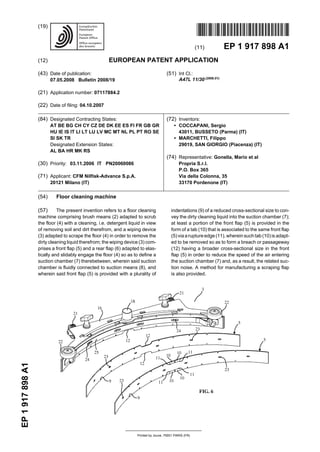
  • 2. (11) EP 1 917 898 A1 (12) EUROPEAN PATENT APPLICATION (43) Date of publication: 07.05.2008 Bulletin 2008/19 (21) Application number: 07117884.2 (22) Date of filing: 04.10.2007 (51) Int Cl.: A47L 11/30 (2006.01) (84) Designated Contracting States: AT BE BG CH CY CZ DE DK EE ES FI FR GB GR HU IE IS IT LI LT LU LV MC MT NL PL PT RO SE SI SK TR Designated Extension States: AL BA HR MK RS (30) Priority: 03.11.2006 IT PN20060086 (71) Applicant: CFM Nilfisk-Advance S.p.A. 20121 Milano (IT) (72) Inventors: • COCCAPANI, Sergio 43011, BUSSETO (Parma) (IT) • MARCHETTI, Filippo 29019, SAN GIORGIO (Piacenza) (IT) (74) Representative: Gonella, Mario et al Propria S.r.l. P.O. Box 365 Via della Colonna, 35 33170 Pordenone (IT) (54) Floor cleaning machine (57) The present invention refers to a floor cleaning machine comprising brush means (2) adapted to scrub the floor (4) with a cleaning, i.e. detergent liquid in view of removing soil and dirt therefrom, and a wiping device (3) adapted to scrape the floor (4) in order to remove the dirty cleaning liquid therefrom; the wiping device (3) com- prises a front flap (5) and a rear flap (6) adapted to elas- tically and slidably engage the floor (4) so as to define a suction chamber (7) therebetween, wherein said suction chamber is fluidly connected to suction means (8), and wherein said front flap (5) is provided with a plurality of indentations (9) of a reduced cross-sectional size to con- vey the dirty cleaning liquid into the suction chamber (7); at least a portion of the front flap (5) is provided in the form of a tab (10) that is associated to the same front flap (5) viaa ruptureedge (11),wherein such tab (10) is adapt- ed to be removed so as to form a breach or passageway (12) having a broader cross-sectional size in the front flap (5) in order to reduce the speed of the air entering the suction chamber (7) and, as a result, the related suc- tion noise. A method for manufacturing a scraping flap is also provided.
  • 3. EP 1 917 898 A1 2 5 10 15 20 25 30 35 40 45 50 55 Description [0001] The present invention refers to a floor cleaning machine. [0002] Floor cleaning, i.e. washing-drying machines usually comprise a brushing device with water and/or liq- uid detergent dispensing provision to wash the floor, as well as a wiping device to remove the dirty liquid from the floor and dry up the latter. [0003] Such wiping device has the purpose of scraping and vacuuming the floor behind the brushing device, in order to remove the dirty liquid therefrom by taking it in through suction means, which it is appropriately connect- ed with. [0004] The wipingdeviceisusuallycomprised ofasup- port, to which there are mounted two flaps (or wiping blades, as they are generally referred to in the art) that are made of a rubber-based or rubber-like material to be able to elastically and slidably engage the floor to be cleaned. These flaps, i.e. a front one - facing forwards, i.e. in the forward direction of movement of the machine - and a rear one, are biased, i.e. pressed against the floor so as to substantially act as sealing gaskets and delim- itate a suction chamber therebetween, which is connect- ed to the suction or vacuuming means via a conduit. The rear flap has usually a larger thickness and is made of a softer material featuring a greater resistance to water and detergent liquid, since it must perform as to be able to retain the dirty washing liquid inside the chamber for it to be effectively removed by suction. [0005] The front flap has the task of conveying the liq- uid into the suction chamber and, to this purpose, it is in fact provided with a plurality of indentations or cuts made along the floor scraping border, i.e. the border in contact with the floor, so as to allow the washing liquid to seep into and enter the suction chamber. The provision of such indentations or cuts has the effect of reducing the nega- tive pressure being created by the suction means inside the chamber, but allows for a correct removal of the air- liquid mixture by suction. [0006] While seeping through such indentations or cuts, the air and the liquid generate some noise. [0007] Now, the higher is the speed of the air being sucked in through the indentations and, as a result, the greater is the negative pressure inside the suction cham- ber, the higher is the noise generated. [0008] Generally, however, the greater is the negative pressure that is created inside the suction chamber, the better is the ability of the liquid to be effectively removed from the floor by suction. [0009] By increasing the overall dimensions of the in- dentations or cuts in the front flap, i.e. by providing ap- ertures with a broader cross-section, the negative pres- sure created inside the suction chamber and, as a result, the overall suction capacity are reduced, but the effect is on the other hand obtained in this way of drastically reducing the noise generated by the air being sucked in and passing through the indentations. [0010] When treating some kinds of floors (typically those paved with tiles and featuring fissures and junc- tures), the negative pressure shall necessarily be high enough so as to allow the liquid to be correctly and ef- fectively removed by suction, even if this involves - as a consequence - a greater noise emission, which people are anyway willing to accept since the priority - in these cases - lies in ensuring the highest possible suction ca- pacity. [0011] On other kinds of floors (e.g. linoleum-covered floors, marble floors, and the like), the suction capacity may be equally effective even with a lower negative pres- sure prevailing inside the suction chamber and, there- fore, under a reduced emission of noise. [0012] In certain places and environments (e.g. indus- trial premises, supermarkets, gyms, and the like) the pre- vailing priority lies in having or obtaining a great suction capacity at the expense of a considerable extent of noise emitted. [0013] In other places (such as hospitals, schools, and the like), people are rather willing to accept a relatively lower suction effectiveness, since the priority lies in this case in ensuring as low as possible an emission of noise. [0014] Floor-cleaning equipment manufacturers cur- rently provide front flaps featuring either indentations of a reducedcross-section size, so as to ensure a maximum extent of suction capacity, or larger-sized indentations that favour a low emission of noise, while giving up part of the suction effectiveness. [0015] It has however been found that, in the case of front flaps provided with indentations with a reduced cross-section size (i.e. aimed at obtaining a maximum extent of negative pressure created inside the suction chamber), the final equipment users themselves tend to manually provide - using scissors or similar tools - larger- sized apertures in view of reducing the noise level of the machines. [0016] It may of course be quite readily appreciated that such tampering is quite difficult a job, and further requires a lot of time to be completed, since it involves the front flap to be removed from the wiping device, the additional aperture or apertures to be cut thereinto, and finally the so re-processed front flap to be assembled again on to the wiping device. [0017] It can furtherbereadily appreciated that - during the process of making such additional apertures in the front flap, i.e. a process that largely depends on the skills and the experience of the user carrying it out - the front flap may itself be caused - owing to errors in tampering therewith or similar problems - to undergo tears and sim- ilar damages that might even impair the good state and operativeness thereof, up to making it necessary for it to be totally replaced. [0018] It is therefore a main object of the present in- vention to provide a floor-cleaning machine that is pro- vided with a front flap that does away with the afore-cited drawbacks of prior-art equipment. [0019] Within this general object, it is a purpose of the 1 2
  • 4. EP 1 917 898 A1 3 5 10 15 20 25 30 35 40 45 50 55 present invention to provide a front flap that is more ver- satile and practical than the front flaps being currently available on the market, and is capable of being used so as to selectively favour the suction capacity or a reduced noise level of the machine, in accordance with the re- quirements of the user. [0020] A further purpose of the present invention is to provide a flap that is simple in its construction and reliable in use, as well as capable of being manufactured at fully competitive costs. [0021] According to the present invention, these aims, along with further ones that will become apparent from the following disclosure, are reached in a floor-cleaning machine and a method for providing a flap that incorpo- rate the features and characteristics as defined and re- cited in claim 1 et seq. appended hereto. [0022] Advantages and features of the present inven- tion will anyway be more readily understood from the description of a preferred, although not sole embodiment that is given below by way of non-limiting example with reference to the accompanying drawings, in which: - Figure 1 is a perspective front view of the floor-clean- ing machine according to the present invention; - Figure 2 is a perspective rear view of the floor-clean- ing machine according to the present invention; - Figure 3 is a perspective bottom view of the wiping device and the related support; - Figure 4 is an enlarged, side cross-sectional view of the wiping device; - Figure 5 is an exploded view of the wiping device; - Figure 6 is a perspective front view of the wiping device and the front flap with both associated and removed tabs; - Figure 7 is a front view of the front flap in its integral state and with both associated and removed tabs. [0023] With reference to the above-noted Figures, the floor cleaning machine according to the present inven- tion, as generally indicated with the reference numeral 1 there, comprises brush means 2 adapted to scrub the floor 4 with a cleaning, i.e. detergent liquid in view of removing soil and dirt therefrom, and a wiping device 3 adapted to scrape the floor 4 in order to remove the dirty cleaning liquid therefrom. [0024] The wiping device 3 comprises a front flap 5 and a rear flap 6 adapted to elastically and slidably en- gage the floor 4 to define a suction chamber 7 therebe- tween, wherein said suction chamber is fluidly connected to suction means 8. In addition, the front flap 5 is provided with a plurality of indentations 9 of a reduced cross-sec- tional size to convey the dirty cleaning liquid into the suc- tion chamber 7. [0025] Advantageously, at least a portion of the front flap 5 is provided in the form of a tab 10 that is associated to the same front flap via a rupture edge 11. Such tab 10 is adapted to be removed so as to form a breach or pas- sageway 12 having a broader cross-sectional size in the front flap 5 in order to reduce the speed of the air entering the suction chamber 7 and, as a result, the related suction noise. [0026] The floor cleaning machine comprises a frame or chassis 13 with a housing body 14 rising thereabove for the various component parts of the machine to be accommodated therein. The brushing means 2 may for instance comprise a pair of rotary brushes located at a front end portion of the chassis 13 of the machine along with appropriate motor means (not shown in the draw- ings) to rotatably drive said brushes. In addition, the floor cleaning machine comprises a reservoir for storing a liq- uid detergent which, by means of a pump, is delivered to the brushes so that the same brushes - as driven ro- tatably by said motor means - rub the liquid detergent onto the floor 4 to remove soil and dirt therefrom. For the resulting dirty liquid detergent to be then removed from the floor 4, the machine is provided with a wiping device 3, which is provided on the rear end portion of the chassis 13 and connected to suction means 8.The suctionmeans 8 comprise a suction pump or compressor located within the housing body 14 and connected - via appropriate conduits - with the wiping device 3 and a recovery con- tainer provided in the same housing body 14. When the pump is operated, the dirty detergent liquid is taken in by suction through the wiping device 3, which trails grazingly along the floor 4 behind the brushes, to be eventually sent to the recovery container. [0027] The wiping device 3 comprises a support mem- ber 16 provided in an arcuate shape, which defines a cavity 17 that is open towards the floor 4. In practice, suchsupportmember 16hasacross-section intheshape of a U turned downwards, which defines a delimited space facing towards the floor along which the wiping device 3 is due to sweep. [0028] The suction means 8 are connected to the wip- ing device 3 via a suction conduit 18 that fluidly commu- nicates with the cavity 17 of the support member 16; in particular, the suction conduit 18 is connected to a middle portion of the support member 16. The support member 16 defines an arcuate front surface 19 facing forwards, i.e.inthe direction offorwardmovement ofthe floor clean- ing machine, and an arcuate rear surface 20, which com- bine to define the space of the cavity 17 connected to the suction conduit 18. [0029] A front scraping flap 5 and a rear scraping flap 6 are associated to the arcuate front surface 19 and the arcuate rear surface 20 of the support member 16, re- spectively, so as to wipe, i.e. scrape the wet floor and remove the dirty liquid therefrom. [0030] The flaps 5, 6 (which are commonly referred to as the wiper blades in the art) are generally made of a 3 4
  • 5. EP 1 917 898 A1 4 5 10 15 20 25 30 35 40 45 50 55 suitable plastic-rubber material, such as NR, SBR, neo- prene, polyurethane, just to name a few, are intended to elastically and slidably engage the floor 4 and define a suction chamber 7 therebetween, which is connected to the suction conduit 18 via the support member 16. In practice, such flaps 5, 6, that are biased, i.e. pressed into contact with the floor, perform as gaskets adhering against the floor to create the suction chamber 7. The front flap 5 is provided with a sequence of indentations or cuts 9 of a reduced cross-sectional size along the bor- der of the flap 5 due to engage the floor, so as to enable the mixture formed of air and dirty cleaning liquid to seep therethrough into the suction chamber 7, thereby remov- ing the liquid from the floor. Such indentations 9, there- fore, have the purpose of conveying the dirty cleaning liquid into the space comprised between the flaps, where - owing to the negative pressure created by the suction means 8 - the liquid is removed from the floor by suction. [0031] The arcuate shape, featuring a concavity ori- ented in the direction of forward movement of the floor cleaning machine, of the support member 16 and, as a result, of the suction chamber 7 being defined between the two flaps 5, 6, enables the liquid to be directed to- wards the middle portion of the cavity 17 of the support member 16, where the suction conduit 18 is provided. A pair of wheels 21 are provided to prevent the support member 16, which is usually made of a rigid material, e.g. metal, from being dragged along on the floor when the floor cleaning machine is being used. A pair of side castors 22 are provided to prevent the side end portions ofthesupportmember16 from scouring againstthelower portion of a wall when the floor cleaning machine is used to wash a portion of floor lying close to such wall. [0032] The flaps 5, 6 feature a sequence of perfora- tions 23 provided centrally all along the flaps and adapted to engage corresponding projections 24 provided on the front surface 19 and the rear surface 20 of the support member 16. Clamping bands 25 are adapted to snap onto such projections 24 so as to removably fasten the flaps 5, 6 to the support member 16 and enable them to be quickly and conveniently removed for replacement or similar requirements. [0033] The wiping device 3 is attached to the floor cleaning machine by means of an upright pin 26 associ- ated on to the chassis 13, to which there is secured a first bracket 27 adapted to rotate about such pin 26 along a horizontal plane. The support member 16 is secured to a second bracket 28 hinged on to the first bracket 27 along a horizontal axis, about which it is free to swing. Spring means 29 bias the second bracket 27 towards the floor so as to ensure that the flaps 5, 6 keep elastically engaging the floor in an adequate manner to effectively create the afore-mentioned suction chamber 7 therebe- tween. [0034] The front flap 5 advantageously comprises at least a rupture portion - situated close to or along the floor-scraping border thereof - that is adapted to be torn off by a user in view of creating a breach or passageway 12 in the same flap having a broader cross-sectional size than the indentations 9. The thus created gap or breach 12 enables the overall size of the apertures in the front flap 5 to be increased and, as a result, the negative pres- sure prevailing inside the suction chamber 7 and, there- fore, the speed of the air seeping into the chamber to be reduced accordingly, with the result of a drastically re- duced noise generated by the suction effect. [0035] The rupture portion to be torn off the front flap in view of forming a related breach or gap consists of a tab 10 associated to the front flap 5 via a tear-off edge 11 that enables the tab 10 to be removed by simply tear- ing it off. [0036] Mostobviously, said rupture edge 11 will be suf- ficiently strong and resistant as to prevent the tab 10 from breaking off accidentally during normal operation of the wiping device 3, in the case that the tab 10 is preferably left in position in view of obtaining a maximum extent of suction capacity, regardless of the noise. [0037] In the opposite case, i.e. when particular low- noise requirements are to be complied with, all it takes is tearing the tab 10 off to reduce the suction noise of the machine accordingly. [0038] The rupture edge 11 may be obtained by for example making a sequence of microperforations along a contour delimiting the portion of front flap 5 to be re- moved to create the breach or gap 12, wherein it will be readily appreciated that a number of other techniques may be used to obtain the same result, such as by prop- erly pressing or constricting the front flap 5 along the contour of the portion to be torn off, so as to reduce the tensile, i.e.rupture strength oftheflap along said contour. [0039] It is contemplated that the indentations 9 having a reduced cross-sectional size be provided along both longitudinal borders of the front flap 5, so that no need will exist for the front flap 5 to be strictly applied on to the support member 16 in a preferential way, direction or position. Furthermore, when a longitudinal border even- tually wears out to the point that the same operating ef- fectiveness of the machine is impaired, all it takes is dis- assembling the flap 5, turning it upside down and fasten- ing it again on to the related support member 16 so that the still intact border thereof is now facing towards the floor. [0040] To the same purpose, even the tear-off tab 10 is provided along both longitudinal borders of the front flap 5. [0041] In particular, the tear-off tabs 10 and the related rupture edges 11 are provided close to the middle portion of the front flap 5 along both longitudinal borders thereof. [0042] Fully apparent from the above description is therefore the ability of the present invention to effectively reach the afore-cited aims and advantages by providing a floor cleaning machine provided with a front flap that is particularly simple from a construction point of view, as well as reliable in use and requiring just a simple, quick handling in view of providing a larger-sized breach or gap in the same flap. 5 6
  • 6. EP 1 917 898 A1 5 5 10 15 20 25 30 35 40 45 50 55 [0043] It will be readily appreciated that the flap ac- cording to the present invention may be embodied in a number of manners differing from the above-described one, and may be the subject of a number of further mod- ifications, without departing from the scope of the present invention. Moreover, all afore-described details may be replaced by technically equivalent elements. [0044] It should finally be noticed that the materials used to manufacture the flap of the present invention, as well as the shapes and the sizing of the individual com- ponent parts thereof, may each time be selected so as to more appropriately meet the particular requirements or suit the particular application, again without departing from the scope of the present invention. Claims 1. Floor cleaning machine comprising brush means (2) adapted to scrub the floor (4) with a cleaning, i.e. detergent liquid in view of removing soil and dirt therefrom, and a wiping device (3) adapted to scrape the floor (4) in order to remove the dirty cleaning liquid therefrom, said wiping device (3) comprising afront flap(5)andarearflap(6)adapted toelastically and slidably engage the floor (4) so as to define a suction chamber (7) therebetween, wherein said suction chamber is fluidly connected to suction means (8), and wherein said front flap (5) is provided with a plurality of indentations (9) of a reduced cross- sectional size to convey the dirty cleaning liquid into the suction chamber (7), characterized in that at least a portion of the front flap (5) is provided in the form of a tab (10) that is associated to the same front flap (5) via a rupture edge (11), wherein such tab (10) is adapted to be removed so as to form a breach or passageway (12) having a broader cross-section- al size in the frontflap (5) in order to reduce the speed of the air entering the suction chamber (7) and, as a result, the related suction noise. 2. Method formanufacturing a scraping flap fora wiping device of a floor cleaning machine, said wiping de- vice (3) comprising a front scraping flap (5) and a rear scraping flap (6) adapted to elastically and sli- dably engage the floor (4) so as to define a suction chamber (7) fluidly connected to suction means (8) therebetween, wherein said method comprises the steps of: -providing a sheetofflexible water-resistantma- terial, - cuttinganelongated longitudinalstripfrom said sheet, - making a plurality of indentations (9) of a small cross-sectional size along at least one of the lon- gitudinal borders of such strip, characterized in that it further comprises the step of: - providing a rupture contour (11) delimiting a tab (10) in said strip in order to enable said tab (10) to be simply torn off said strip in view of creating a breach or gap (12) having a broader cross-sectional size to the purpose of reducing thespeedoftheairenteringthesuctionchamber (7) and, as a result, the related suction noise. 3. Scraping flap for the wiping device of a floor cleaning machine comprising a plurality of indentations (9) of reduced cross-sectional size, characterized in that at least a portion of the front flap (5) is provided in the form of a tab (10) that is associated to the same front flap (5) via a rupture edge (11), wherein such tab (10) is adapted to be removed so as to form a breach or passageway (12) having a broader cross- sectional size in the same front flap (5). 7 8
  • 7. EP 1 917 898 A1 6
  • 8. EP 1 917 898 A1 7
  • 9. EP 1 917 898 A1 8
  • 10. EP 1 917 898 A1 9
  • 11. EP 1 917 898 A1 10
  • 12. EP 1 917 898 A1 11
  • 13. EP 1 917 898 A1 12
  • 14. EP 1 917 898 A1 13