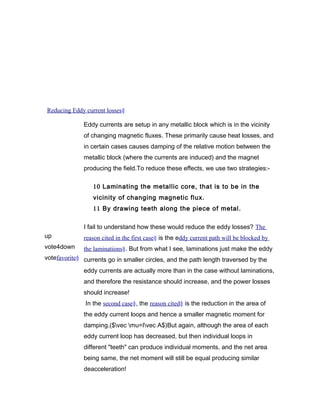
1. Laminating the core breaks up the conductive material into thinner sheets separated by insulating material. This increases the resistance to eddy currents by forcing them to travel longer, more tortuous paths through the laminations.
2. Cutting teeth into the core reduces the cross-sectional area available for eddy currents to flow. With a smaller area, less current can flow and induce smaller magnetic fields, resulting in lower losses.
3. Both techniques reduce eddy current losses by making it more difficult for currents to flow through the conductive material in closed loops in response to changing magnetic fields. This is done by either increasing the resistance and path

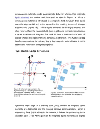
![in the direction of the magnetizing force and the magnetic flux no longer
increases. When H is reduced to zero, some remnant magnetization remains;
this point is known as the retentivity point (+Br). In order to remove this remnant
magnetization, a coercive magnetizing force is applied in the reverse direction.
The point in which there is no longer a magnetic flux (B=0) due to the cancelation
of dipole moments acting in opposite directions is known as the coercivity point (-
Hc). As the magnetizing force increases in the negative direction, the same
saturation occurs as it did before however in the opposite direction (-Hs). The
loop continues with an equal but opposite retentivity point (-Br) and coercivity
point (+Hc) until its original saturation point (+Hs). Figure 2 portrays this full cycle
hysteresis loop wherein points a and d are the +/- Hs, points b and e are the +/-
Br, and points c and f are the +/- Hc. The magnetic dipole spins at these
respective points can be seen in Figure 3 wherein the spins begin disoriented,
then align with the magnetic field, and finally misalign until the moments cancel
each other out to produce no net magnetic moment. Also notice that the curve
does not ever go back to the origin (B and H=0). In order to get back to this point,
the material will need to be demagnetized (i.e. return to having paramagnetic
behavior) by hitting the material against a surface, reversing the direction of the
magnetizing field, or heating it passed its Neel temperature. At this temperature,
a ferromagnetic material becomes paramagnetic due to thermal fluctuations in
the magnetic dipole moments that disorient the spins.
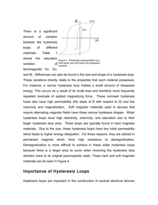
Variations of Hysteresis Loops
Table 1. Saturation point for ferromagnetic materials Fe, Co, and Ni at 0 K.
Metal Hs [A/m]
Fe 1.75 x 10
6
Co 1.45 x 10
6
Ni 0.51 x 10
6](https://image.slidesharecdn.com/eoc2-151029095227-lva1-app6892/85/Eoc-2-10-320.jpg)