The research team designed and built a proof-of-concept mesh network to collect environmental data from two sensors - a light sensor and a piezoelectric sensor - and display it to a base station laptop. The network connects the sensors to Arduino platforms which communicate wirelessly via XBee radios. A Python program formats and displays the sensor data for the user. While the network was able to successfully transmit sensor data, further work is needed to improve sensor reliability and network scalability for practical home implementation.
![8 THE GOVERNOR’S SCHOOL OF ENGINEERING AND TECHNOLOGY 2014
alike, the future application of mesh networks also
grows. Mesh networks can also be used in outdoor
settings where people might have trouble checking
certain conditions manually due to physical limita-
tions. A sensor placed in such areas could provide
a live feed of such conditions, connected in a full
mesh creating a local network that does not require
the internet to send and receive data. Such a net-
work would require sensors that are weather resis-
tant and robust code that ensures network security,
both easily developed and obtained from the open
source movement. Mesh networks, when com-
bined with the advantages of open source, have the
potential to facilitate human to environment inter-
actions.
6. Acknowledgements
We would like to acknowledge our project mentors
Josef Grossmann, Joe Mirizio, Ryan Flynn, and
Edward Kahn from Lockheed Martin who have
generously provided their time along with the nec-
essary resources and information to successfully
complete our proof-of-concept mesh network. The
team would also like to acknowledge the New Jer-
sey Governor’s School of Engineering and Tech-
nology’s Program Director Dr. Ilene Rosen, along
with the Assistant Program Director Jean Patrick
Antoine and the entire GSET staff for present-
ing such an incredible opportunity to the team,
key to the coordination and organization of such
a comprehensive and exciting summer program.
We also extend thanks to our Residential Teach-
ing Assistant Maya Saltzman for overseeing the
project, making sure we had the required tools and
workspace. A final thank you goes to all of the
sponsors of the New Jersey Governor’s School of
Engineering and Technology, specifically Rutgers
University, The State of New Jersey, Morgan Stan-
ley, Lockheed Martin, Silverline Windows, Jersey
South Industries, Inc., The Provident Bank Foun-
dation, and Novo Nordisk.
7. References
[1]
Schmidt, Laurie J. "Sensing Remote Volca-
noes." NASA Earth Observatory. National Aero-
nautics Space Administration, 13 July 2004. Web.
11 July 2014.
[2]
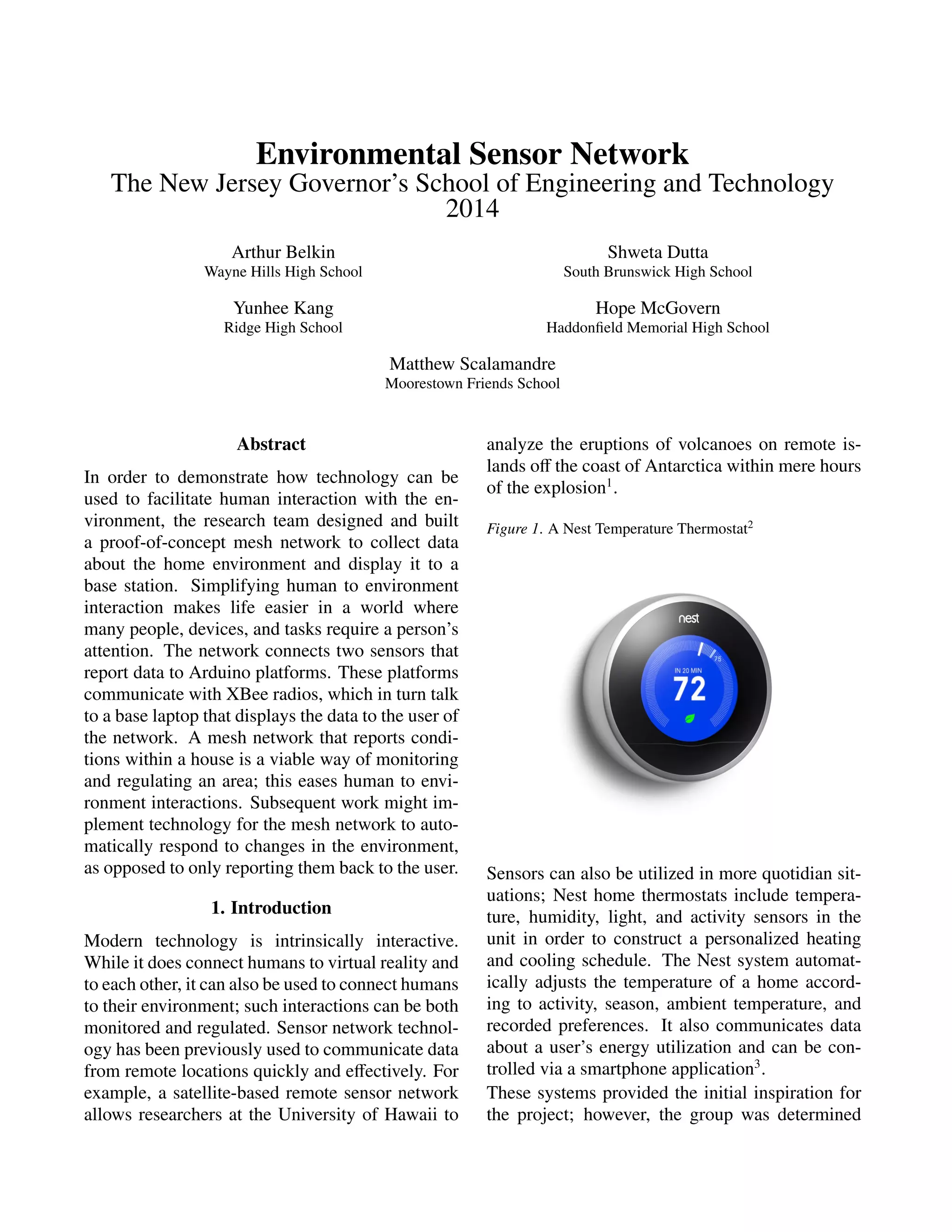
Nest Temperature Thermostat. Digital image.
Amazon. N.p., n.d. Web. 11 July 2014.
[3]
"Home." Nest. Nest Labs, n.d. Web. 13 July
2014.
[4]
Henderson, Harry. "Open-Source Movement."
Science Online. Facts On File News Services, n.d.
Web. 10 July 2014.
[5]
"Arduino Introduction." Arduino - Introduction.
Arduino, n.d. Web. 13 July 2014.
[6]
"What Is an Arduino?" SparkFun. SparkFun
Electronics, 26 Feb. 2013. Web. 8 July 2014.
[7]
Light-To-Frequency Converter Datasheet. N.p.:
Texas Advanced Optoelectronic Solutions, Sept.
2007. PDF.
[8]
Piezoelectric Sound Components. N.p.: Murata
Manufacturing Co., Ltd., n.d. PDF.
[9]
"XBee Buying Guide." SparkFun. SparkFun
Electronics, n.d. Web. 19 July 2014.
[10]
"What Is API (Application Programming Inter-
face) Mode and How Does It Work?" Digi. Digi
International Inc., n.d. Web. 19 July 2014.
[11]
"The AT Command Set." Digi. Digi Interna-
tional Inc., n.d. Web. 19 July 2014.
[12]
Brinton, Stephen. Mesh Networks. N.p.: Gor-
don College, 2009. PPT.
[13]
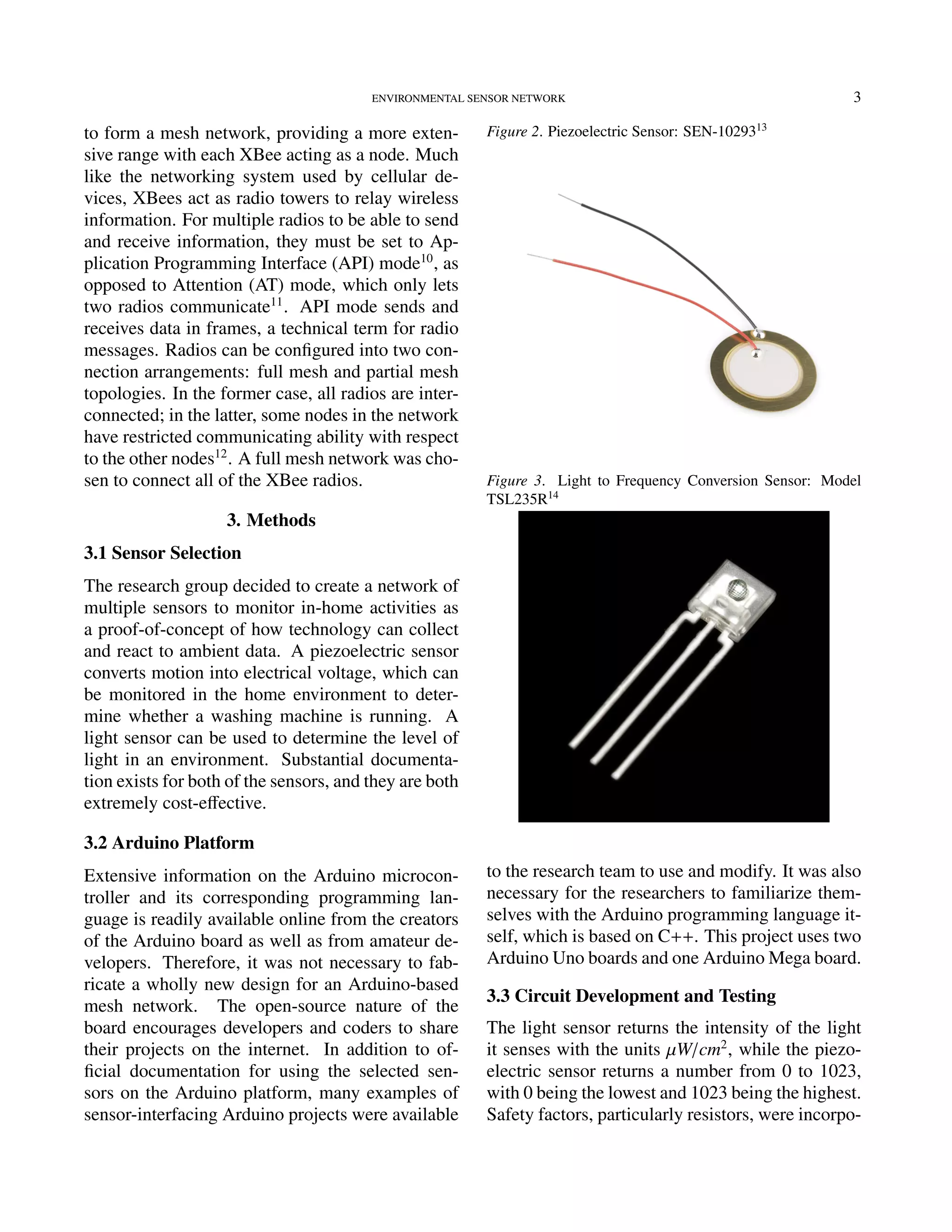
Piezoelectric Sensor. Digital image. SparkFun.
SparkFun Electronics, n.d. Web. 15 July 2014.
[14]
Light to Frequency Conversion Sensor. Digi-
tal image. SparkFun. SparkFun Electronics, n.d.
Web. 15 July 2014.
[15]
Arduino Uno. Digital image. Tested. N.p., n.d.
Web. 15 July 2014.
[16]
Arduino Mega. Digital image. Electroschemat-
ics. N.p., n.d. Web. 15 July 2014.
[17]
XBee S2. Digital image. Entesla. N.p., n.d.
Web. 15 July 2014.
[18]
Liechti, Chris. "Welcome to PySerial’s Doc-
umentation." PySerial. N.p., n.d. Web. 19 July
2014.
[19]
Tillaart, Rob. "Arduino Playground - Sen-
sor TSL235R." Arduino Playground. Arduino, 30
Nov. 2013. Web. 10 July 2014.
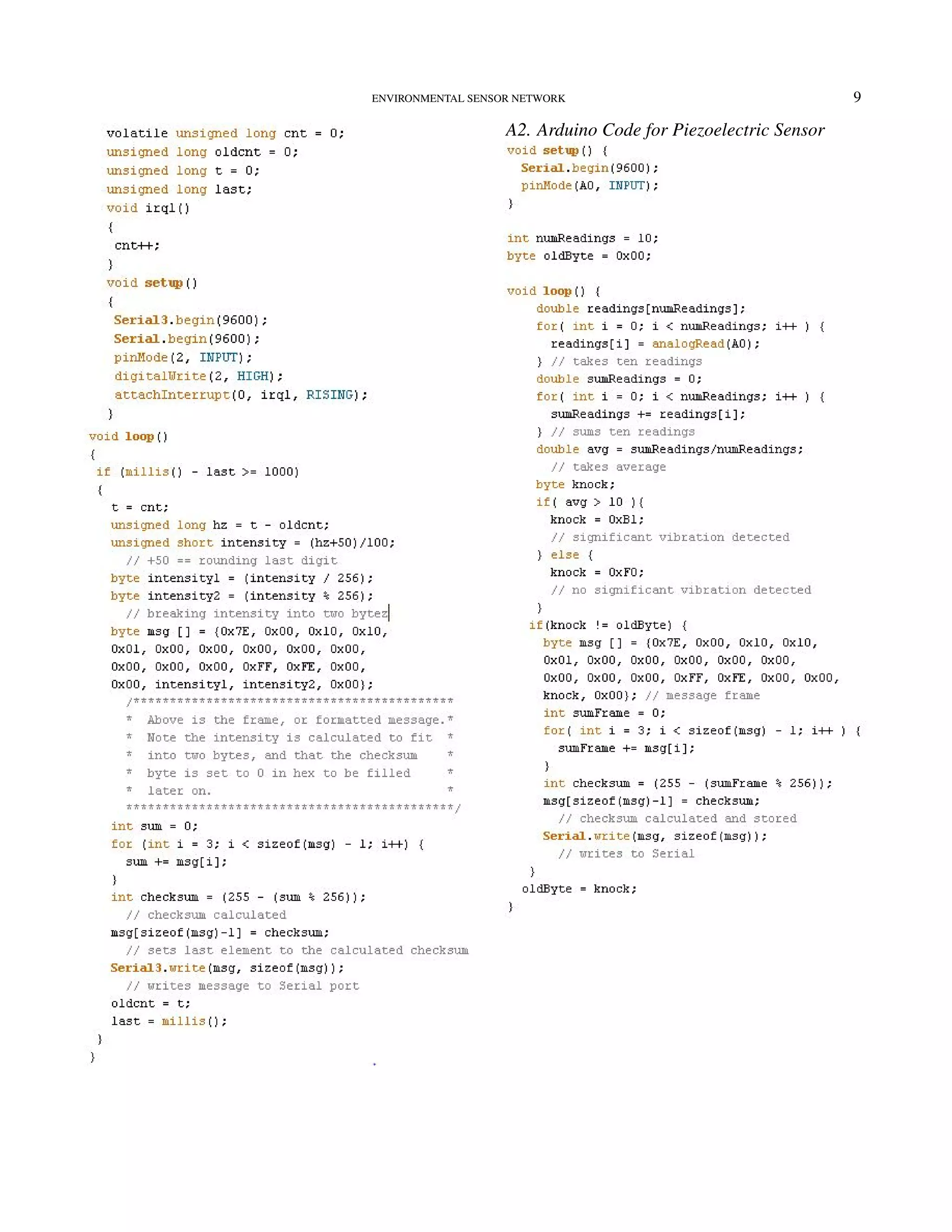
Appendix A
A1. Arduino Code for Light Sensor](https://image.slidesharecdn.com/68da3b1a-3821-4999-ae11-36b84d683cb4-161103152423/75/Environmental-Sensor-Network-Paper-8-2048.jpg)