The imminent rise of 5th generation (5G) wireless standards heralds a pivotal era in cellular communication. Among the challenges faced, selecting an optimal multiple access technique stands out as crucial for achieving the desired blend of low latency, high data rates, and throughput. Generalized frequency division multiplexing (GFDM) emerges as a promising can-didate meeting 5G requirements. This study introduces two innovative pulse shaping filters (PSFs) the better than raised cosine filter (BRCF) and modified bartlett hanning filter (MBHF) paired with various modulation schemes such as binary phase shift keying (BPSK), quadrature phase shift keying (QPSK), and quadrature amplitude modulation (QAM) to assess GFDM signal performance. Considering its spectrum efficiency, QAM modulation emerges as the preferred choice. Performance evaluation of the PSFs entails analyzing symbol error rate (SER) against signal to noise ratio (SNR) across different modulation schemes.
![International Journal of Informatics and Communication Technology (IJ-ICT)
Vol. 14, No. 1, April 2025, pp. 153~163
ISSN: 2252-8776, DOI: 10.11591/ijict.v14i1.pp153-163 153
Journal homepage: http://ijict.iaescore.com
Enhanced pulse shaping filters for minimizing interference in
GFDM signals for 5G cellular networks
Sairam Vamsi Tadikamalla1
, Harish Chandra Mohanta2
, Sudheer Kumar Terlapu3
,
Vamshi Krishna Mandhapati4
1
Centurion University of Technology and Management, Odisha, India
2
Department of Electronics and Communication Engineering, Centurion University of Technology and Management, Odisha, India
3
Shri Vishnu Engineering College for Women, Bhimavaram, India
4
Dhanekula Institute of Engineering and Technology, Vijayawada, India
Article Info ABSTRACT
Article history:
Received Jul 8, 2024
Revised Oct 9, 2024
Accepted Nov 19, 2024
The imminent rise of 5th generation (5G) wireless standards heralds a
pivotal era in cellular communication. Among the challenges faced,
selecting an optimal multiple access technique stands out as crucial for
achieving the desired blend of low latency, high data rates, and throughput.
Generalized frequency division multiplexing (GFDM) emerges as a
promising can-didate meeting 5G requirements. This study introduces two
innovative pulse shaping filters (PSFs) the better than raised cosine filter
(BRCF) and modified bartlett hanning filter (MBHF) paired with various
modulation schemes such as binary phase shift keying (BPSK), quadrature
phase shift keying (QPSK), and quadrature amplitude modulation (QAM) to
assess GFDM signal performance. Considering its spectrum efficiency,
QAM modulation emerges as the preferred choice. Performance evaluation
of the PSFs entails analyzing symbol error rate (SER) against signal to noise
ratio (SNR) across different modulation schemes.
Keywords:
GFDM
Modulation techniques
Pulse shaping filters
SER
This is an open access article under the CC BY-SA license.
Corresponding Author:
Sairam Vamsi Tadikamalla
Department of Electronics and Communication Engineering
Centurion University of Technology and Management
Odisha, India
Email: vamsi.0438@gmail.com
1. INTRODUCTION
In recent years, significant transformations have occurred in both wired and wireless communication
systems, largely driven by the dominance of digital technolo-gy. This shift has created a pressing demand for
high data rates, increased throughput, and minimized latency [1]. Various sectors, including satellite and
military applications, rely on exceptionally high data rates to support real-time connectivity among numerous
devices [2]. Similarly, applications like vehicle automation necessitate minimal latency to swiftly execute
operations, while banking systems require high throughput. Embracing the principles of Industry 4.0, which
advocates for interconnected indus-tries, mandates meeting these criteria [3]. The advent of 5th Generation
(5G) wireless systems is poised to fulfill the demands of Industry 4.0 and global automation [4]. However,
5G technology must address specific requirements, including minimizing out-of-band (OOB) ra-diation and
adjacent channel interference, reducing peak to average power ratio (PAPR), and enabling ultra-reliable, low-
latency communication with an enhanced mobile broadband band [5].
In the realm of 5G technology, researchers face the challenge of achieving high data rates while
minimizing interference, particularly in the context of multi-carrier modulation techniques [6]. Orthogonal
frequency division multiplexing (OFDM), a well-known method employed in 4G and long-term evolution](https://image.slidesharecdn.com/1621138ijict-251027014127-af65557d/75/Enhanced-pulse-shaping-filters-for-minimizing-interference-in-GFDM-signals-for-5G-cellular-networks-1-2048.jpg)
![ ISSN: 2252-8776
Int J Inf & Commun Technol, Vol. 14, No. 1, April 2025: 153-163
154
(LTE) systems, exem-plifies this [7]. OFDM's use of orthogonality and Cyclic Prefix (CP) enhances
robustness and reduces frequency-selective fading compared to single-carrier techniques. However, OFDM
has drawbacks such as high PAPR, inter-carrier interference (ICI), OOB emissions, and reliance on CP usage
[8]. Conse-quently, OFDM has not been adopted for next-generation (5G) systems due to these limitations.
The 5G now group is exploring four alternative waveforms for efficient air interface design, which do not
rely on orthogonality and synchronization requirements [9]. These include filter bank multicarrier (FBMC),
generalized frequency division multiplexing (GFDM), universal filtered multicarrier (UFMC), and Bi-
orthogonal frequency division multiplexing (BFDM) [10]. Each of these techniques aims to reduce Inter-
Symbol Interference (ISI) and increase spectral efficiency. However, GFDM stands out as the only
multiplexing technique offering significantly low OOB radiation, addressing a crucial concern in 5G
technology [11].
GFDM, a prominent multiplexing technique in the realm of 5G, represents the evolution of OFDM.
Its key distinction from OFDM lies in the use of non-rectangular pulses instead of rectangular ones,
eliminating the orthogonality characteristic. GFDM comprises multiple individual blocks, each modulated
separately with multiple sub-carriers, and each subcarrier carrying various symbols [12]. Due to the absence
of or-thogonality, GFDM employs pulse shaping filters (PSFs) to mitigate interference. These PSFs play a
crucial role in altering the characteristics of the modulated signal to be transmitted through the channel,
essential for minimizing ISI caused by high modulation signals through band-limited channels [13]. While
conventional filters like raised cosine filter (RCF) and root raised cosine filter (RRCF) are commonly applied
in multiplexing schemes, they may not effectively reduce interference. This paper introduces novel PSFs
such as better than raised cosine filter (BRCF) and modified bartlett hanning filter (MBHF), offering
significant interference reduction compared to existing techniques [14].
The upcoming sections of the paper delve into the GFDM system model, accompanied by its
performance analysis. This will be followed by a discussion on existing and pro-posed PSFs, along with a
comparative analysis of results.
2. GFDM SYSTEM FRAMEWORK
GFDM employs non-orthogonal multicarrier modulation, transmitting infor-mation across
K subcarriers and N sub-symbols. Unlike traditional methods, GFDM users operate within the same band and
frequency simultaneously, with each user's information distinguished by power levels [15]. Consequently,
GFDM demands sub-stantial computational resources. Additionally, it leverages the superposition
principle at the transmitter and implements successive interference cancellation at the receiver, allowing for
the utilization of the same spectrum for all users. Figure 1 illustrates the block diagram of the GFDM
model [16].
Figure 1. GFDM system model
In the transmitter part of GFDM, several operations are conducted including data generation,
Mapping, GFDM modulation, and the addition of a CP. Con-stellation mapping is performed on binary data](https://image.slidesharecdn.com/1621138ijict-251027014127-af65557d/75/Enhanced-pulse-shaping-filters-for-minimizing-interference-in-GFDM-signals-for-5G-cellular-networks-2-2048.jpg)
![Int J Inf & Commun Technol ISSN: 2252-8776
Enhanced pulse shaping filters for minimizing interference in GFDM … (Sairam Vamsi Tadikamalla)
155
to facilitate transmission over the channel. Among the three mappings available, quadrature amplitude
modulation (QAM) mapper is commonly preferred for its ability to transmit two-bit streams or analog signals
with varying amplitudes in a single transmission. At the receiver, these signals are separated and extracted to
re-construct the original modulating signal [17]. The GFDM Modulator undertakes two pri-mary operations:
Up sampling and pulse shaping. Up sampling increases the modulation of the transmitted signal by
padding zeros, maintaining theintegrity of the con-tent. Additionally, one of the PSFs is applied to generate
the GFDM signal. CP is added to the GFDM signal to mitigate ISI during transmission through the
channel. CP insertion involves append-ing the last M samples of the GFDM symbol to the front of the
symbol [18].
This GFDM signal will be transmitted through the additive white gaussian noise (AWGN) channel
and at receiver equalization is performed to recover transmitted symbols by reducing ISI [19].
- Calculation of SER for GFDM
In order to investigate the performance of different PSFs along with different modulations, it is
necessary to generate GFDM matrix with the help of any PSFs. The previous section discusses different PSFs
and they are indi-cated as Prcf, Pbrcf, and Pmbhf and size of the filter is 1xNSCM [20]. The circular
convolution has to be performed on the matrix obtained due to PSF in order to generate GFDM signal matrix
of size NSCMxNSCM and it is indicated as PC = circshift(P), where P = Prcf/Pbrcf/Pmbhf and PC is the
pulse shaping matrix after applying circular convolution [21]. In GFDM each symbol is the transmitter with a
corresponding pulse shape which is written as,
x[k]= ∑ ∑ 𝑑𝑛,𝑚 𝑃𝑛,𝑚[𝑘]
𝑀−1
𝑚=0
𝑁𝑠𝑐−1
𝑛=0 (1)
where k= 0, 1, 2, --- 𝑁𝑠𝑐 M-1, d = Input binary sequence.
With the help of Pn, m [k] having matrix size 1xNSCM and PC having matrix size NSCM x1, the
GFDM matrix A formed and it can be written as,
x=Ad (2)
where A is called as GFDM modulation matrix with size NSCMxNSCM.
To analyse performance in terms of symbol error rate (SER) and signal to noise ratio (SNR) by
assuming AWGN channel and it can be written as,
PAWGN = 2 (
𝑣−1
𝑣
) 𝑒𝑟𝑓𝑐(√𝛿 ) − (
𝑣−1
𝑣
)
2
𝑒𝑟𝑓𝑐2
(√𝛿 ) (3)
Where 𝛿 =
3𝑅𝑇
2(2𝜇−1)
.
𝐸𝑠
𝑁𝑜
(4)
𝐸𝑠
𝑁𝑜
---SNR in dB
and 𝑅𝑇 =
𝑁𝑆𝐶 . 𝑀
𝑁𝑆𝐶 . 𝑀+𝑁𝐶𝑃+𝑁𝐶𝑆
(5)
𝜇 is the number of bits per binary phase shift keying (BPSK)/quadrature phase shift keying (QPSK)/QAM
symbol, 𝑣 = √2𝜇, NCP and NCS are the length of CP and Cyclic Suffix respectively, 𝐸𝑠 is average energy per
symbol, 𝑁𝑜 is Noise power density.
Now the received signal y is formed by adding transmitted signal with noise.
y = x + PAWGN (6)
This signal has to be demodulated using transpose of GFDM transmitter matrix (A) with the received signal
after channel.
RX = (AT
) * y (7)
After demodulation, the analysis is conducted on the received signal to compare SER against SNR.
Initially, SNR is assumed to be zero, with the size of the matrix equal to SNR in decibels. SER for each SNR
is computed by measuring the difference in errors between the received and transmitted signals [22]. This can
be expressed as (8).](https://image.slidesharecdn.com/1621138ijict-251027014127-af65557d/75/Enhanced-pulse-shaping-filters-for-minimizing-interference-in-GFDM-signals-for-5G-cellular-networks-3-2048.jpg)
![ ISSN: 2252-8776
Int J Inf & Commun Technol, Vol. 14, No. 1, April 2025: 153-163
156
[𝐸𝑒𝑟𝑟, 𝐸𝑎𝑣𝑔] = 𝑠𝑦𝑚𝑒𝑟𝑟 (𝑅𝑋, 𝑥) (8)
The above will compare the elements in two matrices 𝑅𝑋 𝑎𝑛𝑑 𝑥. The number of differences is output
in 𝐸𝑒𝑟𝑟. The ratio of 𝐸𝑒𝑟𝑟 to the number of elements is output of 𝐸𝑎𝑣𝑔. Now the SER will be calculated using.
∑ 𝑆𝐸𝑅 (𝑖) = 𝑆𝐸𝑅(𝑖) + 𝐸𝑎𝑣𝑔
𝑠𝑛𝑟_𝑑𝑏
𝑖=0 (9)
In this paper, the snr_db is taken from 0 to 20 db with 2 db interval.
3. ANALYSIS OF EXISTING PULSE SHAPING FILTER
These filters are integral to the generation of GFDM signals, as they modify the charac-teristics of
the transmitted signal. The primary objective of employing PSFs is to optimize the transmitted signal for the
channel conditions. Trans-mitting highly modulated signals in narrow bandwidth communication channels
often results in ISI. PSFs are utilized to mitigate ISI by narrowing the bandwidth of the modulated signal
in accordance with the channel characteristics, thereby influencing the overall properties of the GFDM
signal [23].
- Raised cosine filter
Unlike the constraints associated with using rectangular pulses in OFDM, the RCF adopts the
fourier transform of a rectangular pulse, namely the sinc pulse. This choice is particularly advantageous for
band-limited data transmission, as it offers superior suitability and performance [24].
Let Prcf (ω) be the spectrum of RCF and γ will be rolling factor then spectrum for RCF is existed in
between.
Prcf(ω) = τ for 0 ≤ ω ≤
π (1−γ)
τ
(10)
Prcf(ω) =
τ
2
(1 − sin ((
τ
2γ
) (ω −
π
τ
))) for
π (1−γ)
τ
≤ ω ≤
π (1+γ)
τ
(11)
Prcf(ω) = 0 for ω ≥
π (1−γ)
τ
(12)
Prcf(ω) forms a sinc pulse which is existed in between
π (1−γ)
τ
≤ ω ≤
π (1+γ)
τ
and no pulse is existed after ω ≥
π (1−γ)
τ
, due to this nature ISI can be reduced.
The time response of Prcf(t) is obtained by applying inverse fourier transform to Prcf(ω).
The response signal of RCF is taken by combining two signals which are 90° phases to each other.
Those signals are:
Prcf1(t) = sin (
πτ
T
(1 − γ)) and Prcf2(t) = cos (
πτ
T
(1 + γ)) then
Prcf(t)=
Prcf1(t)+
4γt
T
Prcf2(t)
πt
T
(1−(
4γt
T
)
2
)
(13)
where γ is roll off factor, the response of GFDM signal is varied by varying γ in between 0 to 1 and T is the
symbol period [25].
4. ANALYSIS OF PROPOSED PULSE SHAPING FILTERS
The existing filter consists of only one variable parameter such as roll off factor (γ). Along with γ,
the proposed filters consist of sensitivity variable and windowing variable. Due to these additional variable
parameters, the shape of the pulse is varied such that interference decreases.
4.1. Better than raised cosine filter
This filter gives better pulse shaping compared to RCF by introducing sensitivity variable named as
β [26]. The response of this filter is given by (14).](https://image.slidesharecdn.com/1621138ijict-251027014127-af65557d/75/Enhanced-pulse-shaping-filters-for-minimizing-interference-in-GFDM-signals-for-5G-cellular-networks-4-2048.jpg)
![Int J Inf & Commun Technol ISSN: 2252-8776
Enhanced pulse shaping filters for minimizing interference in GFDM … (Sairam Vamsi Tadikamalla)
157
Pbrcf1(t) = sin (
πγτ
T
) and Pbrcf2(t) = cos (
πγτ
T
)
Pbrcf(t) = sinc(
τ
T
)
2βτ T Pbrcf1(t)+2 Pbrcf2(t)−1
⁄
1+(βτ T
⁄ )2 (14)
where T is the transmission period and β = ln (2)/ γT.
4.2. Modified bartlett hanning filter
This filter introduces a window shaping parameter denoted as α, typically ranging between 0.5 to
1.88. Remarkably, this parameterization yields superior shaping compared to other filters [27]. The response
of this filter is characterized by (15).
Pmbhf1(t) = sin (
πατ
T
) and Pmbhf2(t) = cos (
πατ
T
)
Pmbhf(t) = sinc(
τ
T
) [(
2 (1−α) Pmbhf1(t)
1−(
2γτ
T
)
2 ) − (
(1−2α) Pmbhf1(t)
(
γπτ
T
)
)] (15)
There are different pulse shapes are formed by varying α and γ parameters. The Table 1 shows those
types of filters.
Table 1. Different PSFs based on α and 𝛾 parameters
Α 𝜸 Type of filter
0.5 to 1.88 0 Rectangular pulse shape filter
0.5 0 to 1 Raised cosine pulse shape filter
1 0 to 1 Bartlett hanning filter
1 1 Frank pulse shaping filter
From the Table 1, when windowing parameter 𝛾 is 0, then type of filter is rectangular pulse shape filter
which is generally used for OFDM modulation techniques [28].
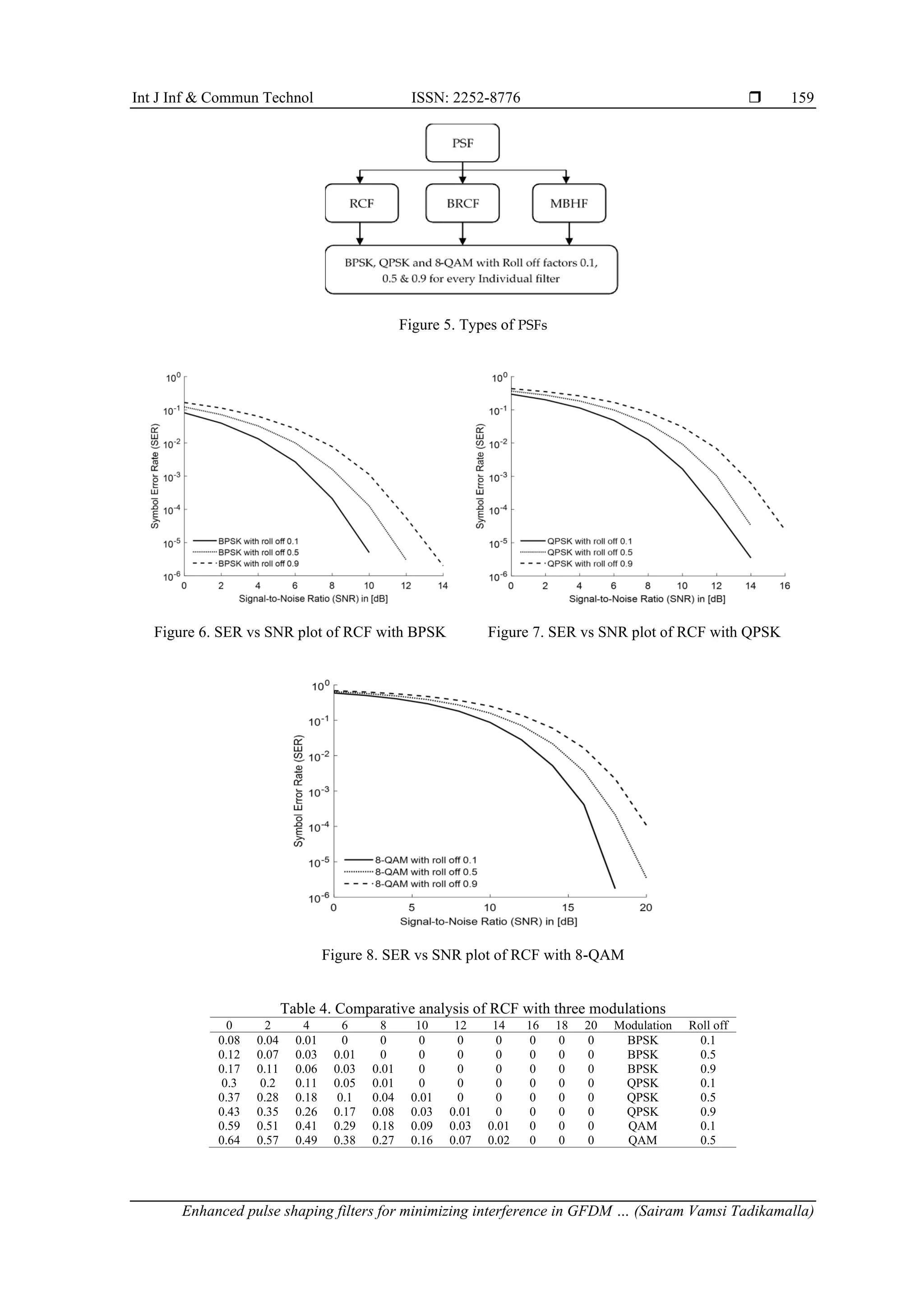
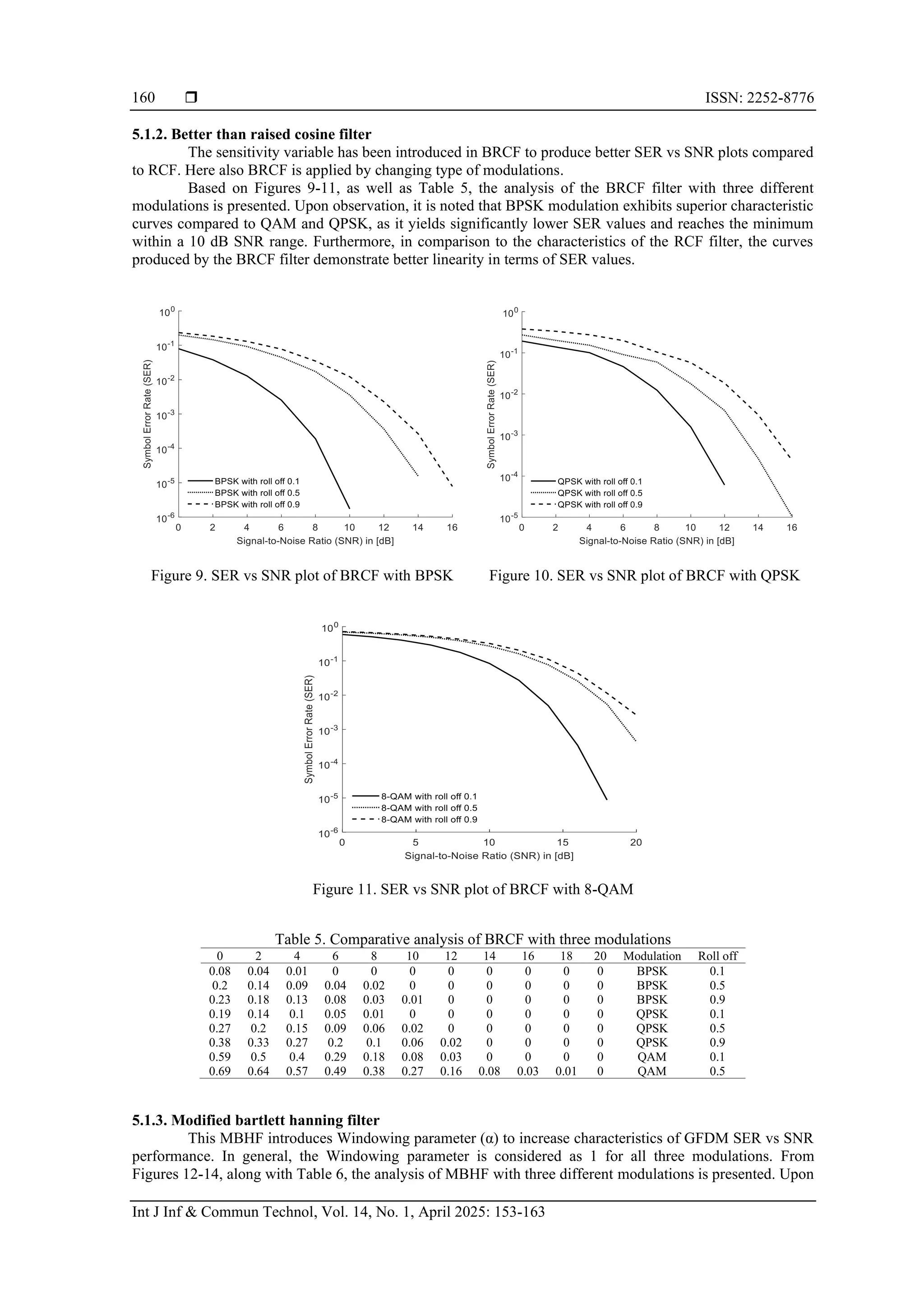
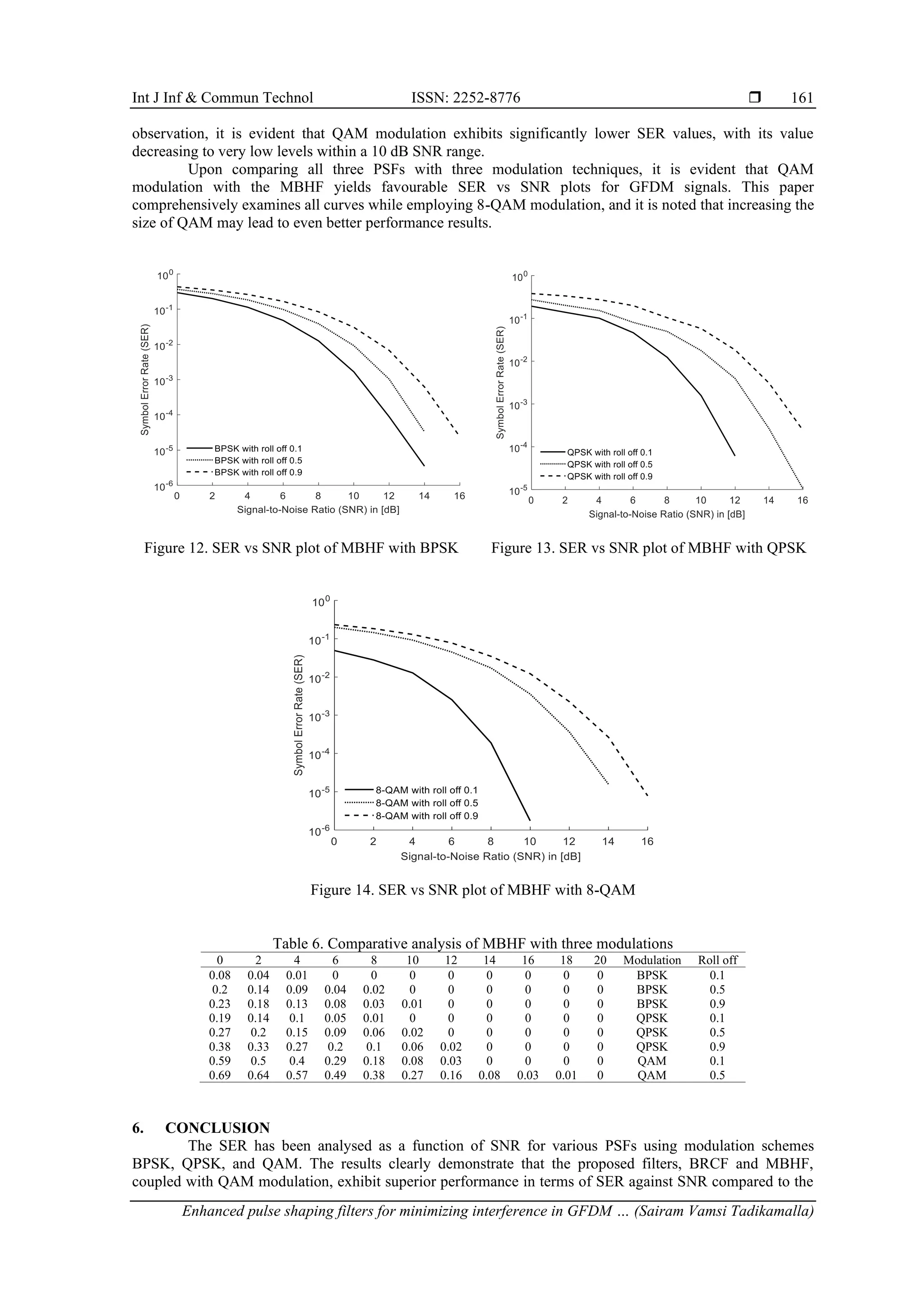
5. RESULTS AND DISCUSSION
In this section, a comparison is conducted among all three PSFs by varying the roll-off factor as 0.1,
0.5, and 0.9. The chosen modulation technique is QAM, as it consistently yields superior results compared to
the other modulation techniques. The simulation environment for this analysis is outlined in Table 2.
Throughout the entire analysis, the roll-off factor is varied as 0.1, 0.5, and 0.9. Typically, the roll-off
factor ranges from 0 to 1, and as it increases from 0 to 1, interference also increases, consequently leading to
higher SER values. Therefore, to facilitate a clear understanding, values are chosen at the initial (0.1), middle
(0.5), and end (0.9) of this range.
Table 2. Simulation environment considered for analysis
Parameter Preferred value
No. of sub carriers 64
Sub symbols per block 6
Cyclic prefix length 16
No of bits per symbol 3
Modulation technique BPSK, QPSK, QAM
PSF RCF, BRCF, MBHF
SNR (in dB) 0, 2, 4 _ _ _ 20
Roll off factor 0.1, 0.5, and 0.9
Window shaping parameter (used only for MBHF) 0.5 to 1.88
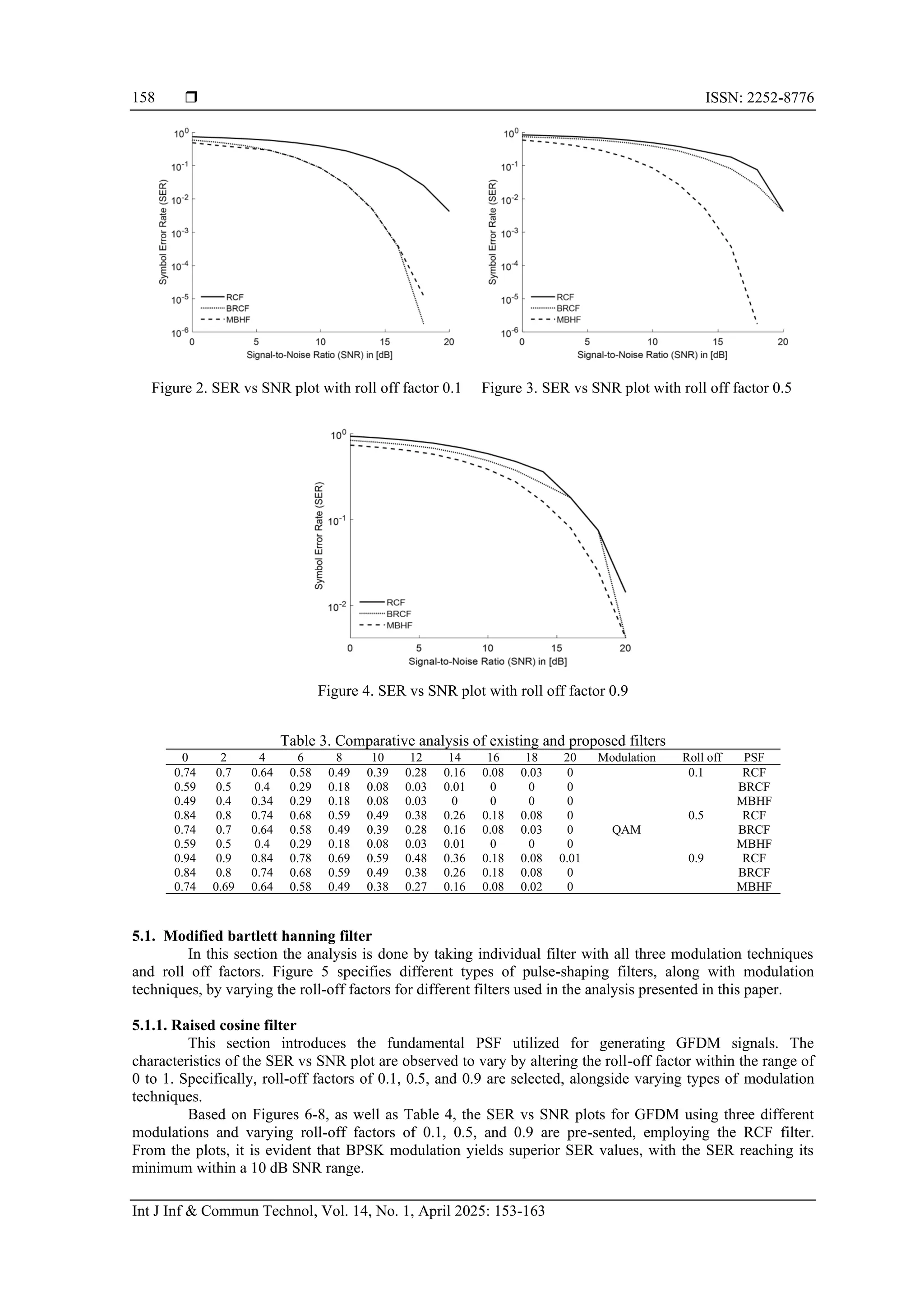
Upon examination of Figures 2-4, along with Table 3, it becomes apparent that the SER is impacted
by an increase in the roll-off factor. Specifically, as the roll-off factor increases, it takes a longer time to
achieve significantly low SER values relative to SNR. Furthermore, it is observed that the MBHF
consistently yields very low SER values in comparison to the other two PSFs. Additionally, MBHF
demonstrates superior linearity characteristics when compared to the remaining filters.](https://image.slidesharecdn.com/1621138ijict-251027014127-af65557d/75/Enhanced-pulse-shaping-filters-for-minimizing-interference-in-GFDM-signals-for-5G-cellular-networks-5-2048.jpg)
![ ISSN: 2252-8776
Int J Inf & Commun Technol, Vol. 14, No. 1, April 2025: 153-163
162
existing RCF filter. Additionally, the roll-off factor is examined for all modulation schemes across the three
filters, revealing that the amplitude of the signal generated with the GFDM scheme decreases while the SER
increases with an increase in the roll-off factor.
REFERENCES
[1] S. P. Bendale and J. Rajesh Prasad, “Security threats and challenges in future mobile wireless networks,” in Proceedings - 2018
IEEE Global Conference on Wireless Computing and Networking, GCWCN 2018, Nov. 2018, pp. 146–150,
doi: 10.1109/GCWCN.2018.8668635.
[2] A. Khalid, “The concept of fifth generation (5G) mobile technology,” Communications on Applied Electronics, vol. 2, no. 8,
pp. 45–48, Sep. 2015, doi: 10.5120/cae2015651853.
[3] Z. Wei et al., “Orthogonal time-frequency space modulation: a promising next-generation waveform,”
IEEE Wireless Communications, vol. 28, no. 4, pp. 136–144, Aug. 2021, doi: 10.1109/MWC.001.2000408.
[4] S. P. Sotiroudis, G. Athanasiadou, G. Tsoulos, P. Sarigiannidis, C. G. Christodoulou, and S. K. Goudos, “Evolutionary ensemble
learning pathloss prediction for 4G and 5G flying base stations with UAVs,” IEEE Transactions on Antennas and Propagation,
vol. 71, no. 7, pp. 5994–6005, Jul. 2023, doi: 10.1109/TAP.2023.3266784.
[5] M. Hu, J. Wang, W. Cheng, and H. Zhang, “Near-optimal piecewise linear companding transform for PAPR reduction of OFDM
systems,” IEEE Transactions on Broadcasting, pp. 1–10, 2024, doi: 10.1109/tbc.2024.3443466.
[6] H. J. Taha and M. F. M. Salleh, “Multi-carrier transmission techniques for wireless communication systems: a survey,”
WSEAS Transactions on Communications, vol. 8, no. 5, pp. 457–472, 2009.
[7] W. Jiang, X. Kuai, X. Yuan, W. Liu, and Z. Song, “Sparsity-learning-based iterative compensation for filtered-
OFDM with clipping,” IEEE Communications Letters, vol. 24, no. 11, pp. 2483–2487, Nov. 2020,
doi: 10.1109/LCOMM.2020.3011680.
[8] S. Jang, D. Na, and K. Choi, “Comprehensive performance comparison between OFDM-based and FBMC-based uplink systems,”
in International Conference on Information Networking, Jan. 2020, vol. 2020-January, pp. 288–292,
doi: 10.1109/ICOIN48656.2020.9016425.
[9] T. S. Vamsi, S. K. Terlapu, and M. V. Krishna, “Investigation of channel estimation techniques using OFDM with BPSK QPSK
and QAM modulations,” in Proceedings - 2022 International Conference on Computing, Communication and Power Technology,
IC3P 2022, Jan. 2022, pp. 209–213, doi: 10.1109/IC3P52835.2022.00051.
[10] K. Kiruthiga and N. R. Nagarajan, “An ease UFMC transmitter using IFFT,” in
2019 International Conference on Intelligent Computing and Control Systems, ICCS 2019, May 2019, pp. 1–5,
doi: 10.1109/ICCS45141.2019.9065779.
[11] S. Kalsotra, A. Kumar, H. D. Joshi, A. K. Singh, K. Dev, and M. Magarini, “Impact of pulse shaping design on OOB emission
and error probability of GFDM,” in IEEE 5G World Forum, 5GWF 2019 - Conference Proceedings, Sep. 2019, pp. 226–231,
doi: 10.1109/5GWF.2019.8911699.
[12] N. Michailow et al., “Generalized frequency division multiplexing for 5th generation cellular networks,” IEEE Transactions on
Communications, vol. 62, no. 9, pp. 3045–3061, Sep. 2014, doi: 10.1109/TCOMM.2014.2345566.
[13] J. Wu, X. Ma, X. Qi, Z. Babar, and W. Zheng, “Influence of pulse shaping filters on PAPR performance of underwater 5G
communication system technique: GFDM,” Wireless Communications and Mobile Computing, vol. 2017, pp. 1–7, 2017,
doi: 10.1155/2017/4361589.
[14] N. C. Beaulieu and M. O. Damen, “Parametric construction of Nyquist-I pulses,” IEEE Transactions on Communications, vol. 52,
no. 12, pp. 2134–2142, Dec. 2004, doi: 10.1109/TCOMM.2004.838739.
[15] A. Lizeaga, P. M. Rodríguez, I. Val, and M. Mendicute, “Evaluation of 5G modulation candidates WCP-COQAM, GFDM-
OQAM, and FBMC-OQAM in low-band highly dispersive wireless channels,” Journal of Computer Networks and
Communications, vol. 2017, pp. 1–11, 2017, doi: 10.1155/2017/2398701.
[16] C. Sharma, S. K. Tomar, and A. Kumar, “A comparison of GFDM and OFDM at same and different
spectral efficiency condition,” in Lecture Notes on Data Engineering and Communications Technologies, vol. 33, 2020,
pp. 282–293.
[17] M. Maraş, E. N. Ayvaz, M. Gömeç, A. Savaşcıhabeş, and A. Özen, “A novel gfdm waveform design based on cascaded
wht-lwt transform for the beyond 5g wireless communications,” Sensors, vol. 21, no. 5, pp. 1–20, Mar. 2021,
doi: 10.3390/s21051831.
[18] M. Sheikh-Hosseini and S. Ahmadi, “Performance analysis of OFDM and GFDM techniques over additive white impulsive noise
channels,” in Conference on Millimeter-Wave and Terahertz Technologies, MMWaTT, Dec. 2022, vol. 2022-December, pp. 1–5,
doi: 10.1109/MMWaTT58022.2022.10172127.
[19] P. Wei, Y. Xiao, L. Dan, L. Ge, and W. Xiang, “N-continuous signaling for GFDM,” IEEE Transactions on Communications,
vol. 68, no. 2, pp. 947–958, Feb. 2020, doi: 10.1109/TCOMM.2019.2952601.
[20] A. Kumar and M. Magarini, “Improved Nyquist pulse shaping filters for generalized frequency division multiplexing,” in 2016
8th IEEE Latin-American Conference on Communications, LATINCOM 2016, Nov. 2016, pp. 1–7,
doi: 10.1109/LATINCOM.2016.7811588.
[21] S. K. Bandari, V. V. Mani, and A. Drosopoulos, “Multi-taper implementation of GFDM,” in IEEE Wireless Communications and
Networking Conference, WCNC, Apr. 2016, pp. 1–5, doi: 10.1109/WCNC.2016.7564952.
[22] T. Sairam Vamsi, S. K. Terlapu, and M. Vamshi Krishna, “PAPR Analysis of FBMC and UFMC for 5G cellular
communications,” in Smart Innovation, Systems and Technologies, vol. 266, 2022, pp. 351–358.
[23] E. N. O. Herawati, A. F. Isnawati, and K. Niamah, “Analysis of GFDM-OQAM performance using zero forcing equalization,” in
10th IEEE International Conference on Communication, Networks and Satellite, Comnetsat 2021 - Proceedings, Jul. 2021,
pp. 135–140, doi: 10.1109/COMNETSAT53002.2021.9530809.
[24] K. Gentile, “The care and feeding of digital pulse-shaping filters,” RF Design, vol. 25, no. 4, pp. 50–59, 2002.
[25] H. M. Abdel-Atty, W. A. Raslan, and A. T. Khalil, “Evaluation and analysis of FBMC/OQAM systems based on pulse shaping
filters,” IEEE Access, vol. 8, pp. 55750–55772, 2020, doi: 10.1109/ACCESS.2020.2981744.
[26] N. C. Beaulieu, C. C. Tan, and M. O. Damen, “A ‘better than’ Nyquist pulse,” IEEE Communications Letters, vol. 5, no. 9,
pp. 367–368, Sep. 2001, doi: 10.1109/4234.951379.](https://image.slidesharecdn.com/1621138ijict-251027014127-af65557d/75/Enhanced-pulse-shaping-filters-for-minimizing-interference-in-GFDM-signals-for-5G-cellular-networks-10-2048.jpg)
![Int J Inf & Commun Technol ISSN: 2252-8776
Enhanced pulse shaping filters for minimizing interference in GFDM … (Sairam Vamsi Tadikamalla)
163
[27] R. Saxena and H. D. Joshi, “Performance improvement in an OFDM system with MBH combinational
pulse shape,” Digital Signal Processing: A Review Journal, vol. 23, no. 1, pp. 314–321, Jan. 2013,
doi: 10.1016/j.dsp.2012.09.010.
[28] M. Kaur, H. D. Joshi, A. kumar, and M. Magarini, “DGT-based pulse shaping filter for generalized frequency division
multiplexing system,” Physical Communication, vol. 61, p. 102227, Dec. 2023, doi: 10.1016/j.phycom.2023.102227.
BIOGRAPHIES OF AUTHORS
Sairam Vamsi Tadikamalla is a research scholar at Centurion University of
Technology and Management, currently working as an embedded software engineer at
Bitsilica since 2023. With a total of 8 years of teaching experience, Vamsi has contributed
significantly to the academic community by publishing 6 international journal papers and 10
international conference papers. Their areas of expertise are embedded and communication
engineering. He can contact at email of vamsi.0438@gmail.com.
Dr. Harish Chandra Mohanta holds an M.Tech. in Electronics and
Communication Engineering from IIT Kharagpur and a Ph.D. in Electrical and Electronics
Engineering from Deakin University, Australia. He has excelled in national level exams like
GATE and UGC-NET and has developed significant expertise in antenna design. His doctoral
research focused on developing a miniaturized rectenna for wireless power and energy
harvesting. With over 16 years of teaching experience, he has published 38 research papers,
authored 5 books, and secured 8 patents. Dr. Mohanta supervises multiple Ph.D. students and
leads the ECE department at Centurion University of Technology and Management. He is also
the CEO of the smart engineering applications research center and director of
miniaturized solutions and applications private limited. He can be contacted at email:
harishmohanta@cutm.ac.in.
Dr. Sudheer Kumar Terlapu holds a B.E in Electronics and Communication
Engineering and an M.Tech in Radar and Microwave Engineering from Andhra University,
where he also earned his Ph.D. in Antenna Array Optimization and Pattern Synthesis. With 18
years of teaching and research experience, he is currently an Associate Professor in ECE at
Shri Vishnu Engineering College for Women. He has published 51 research articles and is a
Senior Member of IEEE, Fellow of IETE, and member of various professional societies.
Dr. Sudheer has served on multiple academic and executive committees, including IEEE and
IETE. He is an active reviewer for several journals and has chaired sessions at international
conferences. His research interests include signal processing and antenna array optimization.
He has guided two Ph.D. scholars and is currently supervising five. Dr. Sudheer has received
awards for his contributions to pedagogical innovation and educational leadership. He can be
contacted at email: profsudheer@ieee.org.
Dr. Vamshi Krishna Mandhapati is a Professor and Head of Department in the
Department of Electronics and Communication Engineering at Dhanekula Institute of
Engineering and Technology, where he has been serving since October 19, 2020. With 13
years of experience, including 11 years in teaching and 2 years in research, Dr. Vamshi
Krishna specializes in Radar and Microwave Engineering. He holds an Ph.D. in
Computational electromagnetics and antennas from Centurion University, Odisha, M.Tech. in
Radar and Microwave from Andhra University, Visakhapatnam, and a B.Tech. in Electronics
and Communication Engineering from JITM under Biju Patnaik University of Technology
(BPUT). His research interests include applied electromagnetics, antenna design, and wireless
communication. Throughout his career, he has contributed significantly to his field, with a
total of 45 publications in both international journals and conferences. He can be contacted at
email: vamshi51@yahoo.co.in.](https://image.slidesharecdn.com/1621138ijict-251027014127-af65557d/75/Enhanced-pulse-shaping-filters-for-minimizing-interference-in-GFDM-signals-for-5G-cellular-networks-11-2048.jpg)


![Coded Agents – with UiPath SDK + LangGraph [Virtual Hands-on Workshop]](https://cdn.slidesharecdn.com/ss_thumbnails/codedagentsdeck-251215155422-5497c599-thumbnail.jpg?width=640&height=640&fit=bounds)


