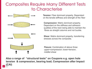
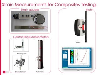
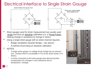
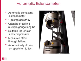
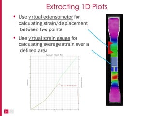
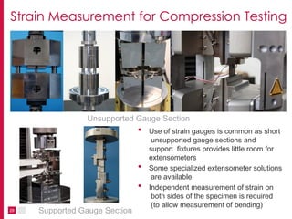
Strain Measurement Techniques for
Composites Testing
2
Topics
• Introduction
• Composite Materials
• Testing of Composite Materials
• Strain Measurement Techniques for
Composite Coupon Testing
• Strain Gauges
• Contacting Extensometers
• Non-contacting Extensometers
• Full-field Strain Measurement
• Examples of Tests
• Tensile
• Compression
• In-Plane Shear (IPS)
Introduction
Composite Materials and Properties
Composite Materials
4
• Two or more distinct phases
• Matrix and Reinforcement
• Common Matrix materials
• Polymer Matrix Composites (PMC)
• Ceramic Matrix Composites (CMC)
• Metal Matrix Composites (MMC)
• Many others e.g. wood
• Common Reinforcements
• Continuous fibers (carbon, glass, basalt)
• Discontinuous fibers / Particles
Today’s focus is on testing of Continuous Fiber
Polymer Matrix Composites (CFRP, GFRP or simply
Carbon/Glass Fiber) Coupons
• 3 Poisson’s ratios
υ12, υ23, υ13
3
1
2
• 3 Tensile moduli/strengths
5
E1t , E2t , E3t , S11t , S22t , S33t
• 3 Shear moduli/strengths
G12, G23, G13 ,,S12, S23, S13
• 3 Compressive moduli/strengths
E1c, E2c , E3c , S11t , S22t , S33t
Composite Material Properties
• Most metals and plastics are isotropic - properties
independent of direction
• Composites are anisotropic - properties depend
on direction
• Composite Intralaminar properties
• Composite Interlaminar fracture properties are important, too!
Tension: Fiber dominant property. Dependant
on the tensile stiffness and strength of the fiber
Compression: Matrix dominant property.
Dependant on the stiffness and adhesion
qualities of the resin being able to maintain the
fibres as straight columns and not buckle.
Shear: Matrix dominant property, transferring
stresses across the composite.
Flexure: Combination of above three:
upper=compression; lower=tension;
middle=shear
6
Composites Require Many Different Tests
to Characterise
Also a range of “structural tests” on Coupons e.g. open hole
tension & compression, bearing load, Compression after Impact
(CAI)
Strain Measurement Techniques for
Coupon Testing
8
Strain Measurement for Coupon Testing
• Require high accuracy/resolution
• Extensometers: ASTM E-83 class B-1/2
• Strain Gauges: Resolution < 50µε (my estimate)
• Non-contacting Video / DIC great for research but not generally used for standard tests
• Most strain measurements on coupons made using either strain gauges or clip-on
extensometers
• Use of averaging Axial strain measurement in order to correct for and/or monitor
specimen bending is common
• Use of Biaxial (Axial + Transverse) strain measurement to determine Poisson’s ratio
and Shear strain
• Majority of composites testing is done at temperature, mostly between -80 to 200 °C
(-112 to +392 °F) but the upper temperature limit is increasing as resins improve
• Composite coupons are often “conditioned” in hot/wet environments or liquids e.g. water,
hydraulic fluids, fuel prior to testing - this can make bonding of gauges difficult
• Explosive failures are common, extensometers often removed prior to failure
9
DIC
Video
Strain Measurements for Composites Testing
Strain gauges Non-
contacting
Contacting Extensometers
Bi-axial clip-on
Axial clip-on
Automatic
Strain
Gauges
• Use of strain gauges is very common in composites testing.
• In some cases e.g. measurement of local shear
strain, there is no extensometer solution available
• In other cases the test specifications mandate the use
of strain gauges
• Use of multiple strain gauges is usual, strain readings are
typically combined to generate
• Average axial / width strain
• Difference in axial strain (bending)
• Shear strain (axial - transverse strain)
10
Electrical Interface to Single Strain Gauge
• Strain gauges used for strain measurement are usually used
singly and have an absolute calibration (i.e. a Gauge Factor
relating change in resistance to change in strain).
• Using a single strain gauge with an strain channel requires:
• Bridge completion (Quarter Bridge – see above)
• A method of providing an absolute calibration.
• NOTES:
• A single active gauge in a voltage driven bridge has an inherent
non- linearity which is acceptable (<1%) at low strain levels (<1%
Strain).
• A 3-wire connection to the strain gauge (see above) provides
compensation for changes in wire resistance due to
temperature changes
11
Verification of Strain Gauge Measurements
• No accepted primary standard
for strain (primary standard for
extensometers is displacement)
• Gauge manufacturer checks
gauges on a sample basis
using bending beam rig or
similar and supplies a
certificate stating the Gauge
Factor
• Strain gauge Gauge Factor is
influenced by the Poisson's
ratio of the material—this can
be important when making
measurements on composites
• Verification of strain gauge data
acquisition channels is performed
using a traceable strain gauge
simulator
12
Contacting Extensometers – Clip-on
• General
• Manually attached
• Strain gauged types - temperature range -70 to
200 ºC
• Capacitive types – temperatures up to 600 ºC
• Averaging Axial
• Corrects for specimen bending
• Versions with independent axial outputs allow for
measurement of average and PBS (Percentage
Bending Strain)
∈𝑓−∈𝑏
∈𝑓+∈𝑏
×
100
𝑃𝐵𝑆
=
• Biaxial
• Versions with Transverse Strain measurement
allow for determination of Poisson’s ratio (∈𝑇
∈
) 𝐴
13
Automatic Extensometer
14
• Automatic contacting
extensometer
• 1 micron accuracy
• Capable of testing
multiple gauge lengths
• Suitable for tension
and compression
• Measures strain
through failure
• Automatically closes
on specimen to test
15
AutoX750 for Composites Testing
• 1µm accuracy
• Robust - arms
can be left on
until failure
• Repeatable
positioning and
attachment
ensures
consistent
results.
• 1µm accuracy
• Low clamping
force does
not damage
specimen.
• Low drag force
minimizes
specimen
bending.
• 1 um accuracy
• Less expensive
than strain
gauges
• Robust - arms
can be left
on until
failure
• Easy to use
Tow – Tensile
ASTM
D4018
Laminate – Tensile
ASTM D3039 &
ISO527-4/5
Laminate
Compression
ASTM D695
Laminate
Flexure
ASTM D790/7264
EN2562/27
46
ISO178/14
125
• 1 um accuracy
• Robust - arms
can be left
on until
failure
• Easy to use
Non-contacting Video Extensometers
Instron AVE 2 Non-contacting Video
Extensometers
• High accuracy strain measurement meets
most composites standards
• The 1 micron accuracy allows measuring
modulus to ISO 527-4/5
• 490 Hz frame rate prevents missing fast
events such as break
• Patented LED lighting and fan system
prevents environmental influences
• Doesn’t require operator to attach
extensometer, reducing operator influence
and increasing consistency
17
Applications of Non-Contacting Video
Extensometers
• Can be used to measure tensile and compressive
strain
• Can be used on chambers for cold and hot tensile tests
• Can be used with any test machine with +/- 10V input
• Can be used for Full-field strain measurement using
Digital Image Correlation software
18
What is Digital Image Correlation?
Images Displacement Strain
19
Analysis of image
surface over time
Use of cross correlation to
determine displacement
Strain calculated
from displacement
An optical method to measure deformation on an object
surface.
How Does it Work?
20
Calculating Full-field Displacement
• Repeated for each subset over the entire surface
• The result is a regular map of displacements over the
entire specimen surface
Specimen
Surface
image
Split into
small
subsets
Pattern
recognised for
each subset
As the specimen deforms, axial (x)
and transverse (y) displacements
for each subset are calculated
21
Calculating Strain
• Strain at each location is
calculated using central
differencing
• Strain calculated in the x and y
directions separately
• For the x direction:
∆𝐿 = 𝐿𝑡 − 𝐿0
𝜀 =
∆𝐿
𝐿
0
22
Analysis of Various Strain and Displacement Data
Axial Strain
Transverse Strain
Shear
Strain
Poisson’s
Ratio
Minimum
Normal Strain
Maximum
Normal Strain
Axial
Displacement Transverse
Displacement
23
Extracting 1D Plots
• Use virtual extensometer for
calculating strain/displacement
between two points
• Use virtual strain gauge for
calculating average strain over a
defined area
24
DIC Example 1 - Vee-notch Shear
• Test to determine shear properties
• V – notched specimen
• Approximately uniform shear stress distribution in notch
• Traditional approach is to use strain gauges mounted at
+/- 45º required to measure shear strain (see below left)
• DIC allows determination of strain distribution (see below
right)
ASTM D 5379
ASTM D 7078
25
DIC Example 2 – Open Hole Tension Test
Shear Strain
26
• Composite Laminate – Open Hole Tension
• Complex 2D strain distribution
• Measure all components of 2D Strain
Tensor (Axial, Transverse, Shear) along with
Maximum and Minimum Principle Strains
Axial Strain
Examples of Strain Measurement in
Composite Tests
28
Strain Measurement for In-Plane Tensile
ASTM D 3039
ISO 527-4/5
EN 2597
• In-plane (laminate) tensile
• Specimens may have different
orientations (e.g. 0/90º)
• Biaxial extensometer or axial + transverse
strain gauges required for determination
of Poisson's ratio
 = - trans / longitudinal
29
Strain Measurement for Compression Testing
• Use of strain gauges is common as short
unsupported gauge sections and
support fixtures provides little room for
extensometers
• Some specialized extensometer solutions
are available
• Independent measurement of strain on
both sides of the specimen is required
(to allow measurement of bending)
Unsupported Gauge Section
Supported Gauge Section
In-Plane Shear Properties by +/- 45 Degree
Tension Test
• Test specimen has fiber directions of +/- 45 degrees
• Test set up similar to tensile test
• Axial and Transverse Strain measured using biaxial
extensometer or axial + transverse strain gauges
• Simple test but not a pure shear stress state
(shear + axial tension)
• Shear Strain = Axial Strain – Transverse Strain
ASTM D 3518
ISO 14129
AITM 1-1002
prEN 6031
30

EMMA Strain Measurements Techniques.pptx

  • 1.
    Strain Measurement Techniquesfor Composites Testing
  • 2.
    2 Topics • Introduction • CompositeMaterials • Testing of Composite Materials • Strain Measurement Techniques for Composite Coupon Testing • Strain Gauges • Contacting Extensometers • Non-contacting Extensometers • Full-field Strain Measurement • Examples of Tests • Tensile • Compression • In-Plane Shear (IPS)
  • 3.
  • 4.
    Composite Materials 4 • Twoor more distinct phases • Matrix and Reinforcement • Common Matrix materials • Polymer Matrix Composites (PMC) • Ceramic Matrix Composites (CMC) • Metal Matrix Composites (MMC) • Many others e.g. wood • Common Reinforcements • Continuous fibers (carbon, glass, basalt) • Discontinuous fibers / Particles Today’s focus is on testing of Continuous Fiber Polymer Matrix Composites (CFRP, GFRP or simply Carbon/Glass Fiber) Coupons
  • 5.
    • 3 Poisson’sratios υ12, υ23, υ13 3 1 2 • 3 Tensile moduli/strengths 5 E1t , E2t , E3t , S11t , S22t , S33t • 3 Shear moduli/strengths G12, G23, G13 ,,S12, S23, S13 • 3 Compressive moduli/strengths E1c, E2c , E3c , S11t , S22t , S33t Composite Material Properties • Most metals and plastics are isotropic - properties independent of direction • Composites are anisotropic - properties depend on direction • Composite Intralaminar properties • Composite Interlaminar fracture properties are important, too!
  • 6.
    Tension: Fiber dominantproperty. Dependant on the tensile stiffness and strength of the fiber Compression: Matrix dominant property. Dependant on the stiffness and adhesion qualities of the resin being able to maintain the fibres as straight columns and not buckle. Shear: Matrix dominant property, transferring stresses across the composite. Flexure: Combination of above three: upper=compression; lower=tension; middle=shear 6 Composites Require Many Different Tests to Characterise Also a range of “structural tests” on Coupons e.g. open hole tension & compression, bearing load, Compression after Impact (CAI)
  • 7.
  • 8.
    8 Strain Measurement forCoupon Testing • Require high accuracy/resolution • Extensometers: ASTM E-83 class B-1/2 • Strain Gauges: Resolution < 50µε (my estimate) • Non-contacting Video / DIC great for research but not generally used for standard tests • Most strain measurements on coupons made using either strain gauges or clip-on extensometers • Use of averaging Axial strain measurement in order to correct for and/or monitor specimen bending is common • Use of Biaxial (Axial + Transverse) strain measurement to determine Poisson’s ratio and Shear strain • Majority of composites testing is done at temperature, mostly between -80 to 200 °C (-112 to +392 °F) but the upper temperature limit is increasing as resins improve • Composite coupons are often “conditioned” in hot/wet environments or liquids e.g. water, hydraulic fluids, fuel prior to testing - this can make bonding of gauges difficult • Explosive failures are common, extensometers often removed prior to failure
  • 9.
    9 DIC Video Strain Measurements forComposites Testing Strain gauges Non- contacting Contacting Extensometers Bi-axial clip-on Axial clip-on Automatic
  • 10.
    Strain Gauges • Use ofstrain gauges is very common in composites testing. • In some cases e.g. measurement of local shear strain, there is no extensometer solution available • In other cases the test specifications mandate the use of strain gauges • Use of multiple strain gauges is usual, strain readings are typically combined to generate • Average axial / width strain • Difference in axial strain (bending) • Shear strain (axial - transverse strain) 10
  • 11.
    Electrical Interface toSingle Strain Gauge • Strain gauges used for strain measurement are usually used singly and have an absolute calibration (i.e. a Gauge Factor relating change in resistance to change in strain). • Using a single strain gauge with an strain channel requires: • Bridge completion (Quarter Bridge – see above) • A method of providing an absolute calibration. • NOTES: • A single active gauge in a voltage driven bridge has an inherent non- linearity which is acceptable (<1%) at low strain levels (<1% Strain). • A 3-wire connection to the strain gauge (see above) provides compensation for changes in wire resistance due to temperature changes 11
  • 12.
    Verification of StrainGauge Measurements • No accepted primary standard for strain (primary standard for extensometers is displacement) • Gauge manufacturer checks gauges on a sample basis using bending beam rig or similar and supplies a certificate stating the Gauge Factor • Strain gauge Gauge Factor is influenced by the Poisson's ratio of the material—this can be important when making measurements on composites • Verification of strain gauge data acquisition channels is performed using a traceable strain gauge simulator 12
  • 13.
    Contacting Extensometers –Clip-on • General • Manually attached • Strain gauged types - temperature range -70 to 200 ºC • Capacitive types – temperatures up to 600 ºC • Averaging Axial • Corrects for specimen bending • Versions with independent axial outputs allow for measurement of average and PBS (Percentage Bending Strain) ∈𝑓−∈𝑏 ∈𝑓+∈𝑏 × 100 𝑃𝐵𝑆 = • Biaxial • Versions with Transverse Strain measurement allow for determination of Poisson’s ratio (∈𝑇 ∈ ) 𝐴 13
  • 14.
    Automatic Extensometer 14 • Automaticcontacting extensometer • 1 micron accuracy • Capable of testing multiple gauge lengths • Suitable for tension and compression • Measures strain through failure • Automatically closes on specimen to test
  • 15.
    15 AutoX750 for CompositesTesting • 1µm accuracy • Robust - arms can be left on until failure • Repeatable positioning and attachment ensures consistent results. • 1µm accuracy • Low clamping force does not damage specimen. • Low drag force minimizes specimen bending. • 1 um accuracy • Less expensive than strain gauges • Robust - arms can be left on until failure • Easy to use Tow – Tensile ASTM D4018 Laminate – Tensile ASTM D3039 & ISO527-4/5 Laminate Compression ASTM D695 Laminate Flexure ASTM D790/7264 EN2562/27 46 ISO178/14 125 • 1 um accuracy • Robust - arms can be left on until failure • Easy to use
  • 16.
  • 17.
    Instron AVE 2Non-contacting Video Extensometers • High accuracy strain measurement meets most composites standards • The 1 micron accuracy allows measuring modulus to ISO 527-4/5 • 490 Hz frame rate prevents missing fast events such as break • Patented LED lighting and fan system prevents environmental influences • Doesn’t require operator to attach extensometer, reducing operator influence and increasing consistency 17
  • 18.
    Applications of Non-ContactingVideo Extensometers • Can be used to measure tensile and compressive strain • Can be used on chambers for cold and hot tensile tests • Can be used with any test machine with +/- 10V input • Can be used for Full-field strain measurement using Digital Image Correlation software 18
  • 19.
    What is DigitalImage Correlation? Images Displacement Strain 19 Analysis of image surface over time Use of cross correlation to determine displacement Strain calculated from displacement An optical method to measure deformation on an object surface.
  • 20.
    How Does itWork? 20
  • 21.
    Calculating Full-field Displacement •Repeated for each subset over the entire surface • The result is a regular map of displacements over the entire specimen surface Specimen Surface image Split into small subsets Pattern recognised for each subset As the specimen deforms, axial (x) and transverse (y) displacements for each subset are calculated 21
  • 22.
    Calculating Strain • Strainat each location is calculated using central differencing • Strain calculated in the x and y directions separately • For the x direction: ∆𝐿 = 𝐿𝑡 − 𝐿0 𝜀 = ∆𝐿 𝐿 0 22
  • 23.
    Analysis of VariousStrain and Displacement Data Axial Strain Transverse Strain Shear Strain Poisson’s Ratio Minimum Normal Strain Maximum Normal Strain Axial Displacement Transverse Displacement 23
  • 24.
    Extracting 1D Plots •Use virtual extensometer for calculating strain/displacement between two points • Use virtual strain gauge for calculating average strain over a defined area 24
  • 25.
    DIC Example 1- Vee-notch Shear • Test to determine shear properties • V – notched specimen • Approximately uniform shear stress distribution in notch • Traditional approach is to use strain gauges mounted at +/- 45º required to measure shear strain (see below left) • DIC allows determination of strain distribution (see below right) ASTM D 5379 ASTM D 7078 25
  • 26.
    DIC Example 2– Open Hole Tension Test Shear Strain 26 • Composite Laminate – Open Hole Tension • Complex 2D strain distribution • Measure all components of 2D Strain Tensor (Axial, Transverse, Shear) along with Maximum and Minimum Principle Strains Axial Strain
  • 27.
    Examples of StrainMeasurement in Composite Tests
  • 28.
    28 Strain Measurement forIn-Plane Tensile ASTM D 3039 ISO 527-4/5 EN 2597 • In-plane (laminate) tensile • Specimens may have different orientations (e.g. 0/90º) • Biaxial extensometer or axial + transverse strain gauges required for determination of Poisson's ratio  = - trans / longitudinal
  • 29.
    29 Strain Measurement forCompression Testing • Use of strain gauges is common as short unsupported gauge sections and support fixtures provides little room for extensometers • Some specialized extensometer solutions are available • Independent measurement of strain on both sides of the specimen is required (to allow measurement of bending) Unsupported Gauge Section Supported Gauge Section
  • 30.
    In-Plane Shear Propertiesby +/- 45 Degree Tension Test • Test specimen has fiber directions of +/- 45 degrees • Test set up similar to tensile test • Axial and Transverse Strain measured using biaxial extensometer or axial + transverse strain gauges • Simple test but not a pure shear stress state (shear + axial tension) • Shear Strain = Axial Strain – Transverse Strain ASTM D 3518 ISO 14129 AITM 1-1002 prEN 6031 30