Downloaded 257 times

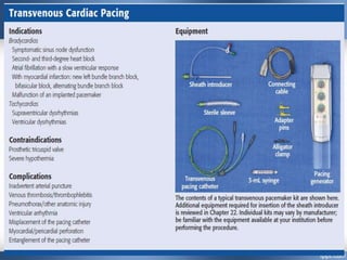
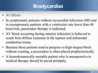
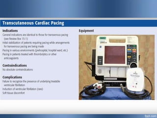


Emergency cardiac pacing can be done prophylactically or therapeutically for symptomatic bradyarrhythmias. Transcutaneous and transvenous pacing are commonly used in emergency departments, with transcutaneous being preferred when time is critical due to its quick noninvasive setup. Transvenous pacing involves inserting a pacing catheter into a vein and threading it to the heart, which can typically be done in under 20 minutes. It is useful for patients requiring prolonged pacing or with high risk of heart block. The document provides details on indications, contraindications, equipment, and techniques for emergency transvenous cardiac pacing.


![Anaesthesia for cardiopulmonary bypass surgery [autosaved]](https://cdn.slidesharecdn.com/ss_thumbnails/anaesthesiaforcardiopulmonarybypasssurgeryautosaved-150531185352-lva1-app6892-thumbnail.jpg?width=640&height=640&fit=bounds)


