Instant Ebook Access,One Click Away – Begin at ebookgate.com
Embedded Systems Design 2nd Edition Steve Heath
https://ebookgate.com/product/embedded-systems-design-2nd-
edition-steve-heath/
OR CLICK BUTTON
DOWLOAD EBOOK
Get Instant Ebook Downloads – Browse at https://ebookgate.com
Click here to visit ebookgate.com and download ebook now
2.
Instant digital products(PDF, ePub, MOBI) available
Download now and explore formats that suit you...
Embedded Systems Architecture Programming and Design 2nd
Edition Raj Kamal
https://ebookgate.com/product/embedded-systems-architecture-
programming-and-design-2nd-edition-raj-kamal/
ebookgate.com
Making Embedded Systems Design Patterns for Great Software
2nd Edition Elecia White
https://ebookgate.com/product/making-embedded-systems-design-patterns-
for-great-software-2nd-edition-elecia-white/
ebookgate.com
Fast and Effective Embedded Systems Design 1st Edition Rob
Toulson
https://ebookgate.com/product/fast-and-effective-embedded-systems-
design-1st-edition-rob-toulson/
ebookgate.com
Design Patterns for Embedded Systems in C An Embedded
Software Engineering Toolkit 1st Edition Bruce Powel
Douglass
https://ebookgate.com/product/design-patterns-for-embedded-systems-in-
c-an-embedded-software-engineering-toolkit-1st-edition-bruce-powel-
douglass/
ebookgate.com
3.
TCP IP LeanWeb Servers for Embedded Systems 2nd Edition
Jeremy Bentham
https://ebookgate.com/product/tcp-ip-lean-web-servers-for-embedded-
systems-2nd-edition-jeremy-bentham/
ebookgate.com
Real Time UML Workshop for Embedded Systems 2nd Edition
Bruce Powel Douglass
https://ebookgate.com/product/real-time-uml-workshop-for-embedded-
systems-2nd-edition-bruce-powel-douglass/
ebookgate.com
Embedded System Design Third Edition Santanu Chattopadhyay
https://ebookgate.com/product/embedded-system-design-third-edition-
santanu-chattopadhyay/
ebookgate.com
Analog and Digital Filter Design 2nd ed Edition Steve
Winder
https://ebookgate.com/product/analog-and-digital-filter-design-2nd-ed-
edition-steve-winder/
ebookgate.com
Programming embedded systems with C and GNU development
tools 2nd Edition Michael Barr
https://ebookgate.com/product/programming-embedded-systems-with-c-and-
gnu-development-tools-2nd-edition-michael-barr/
ebookgate.com
ii Contents
By thesame author
VMEbus: a practical companion
Newnes UNIX™ Pocket Book
Microprocessor architectures: RISC, CISC and DSP
Effective PC networking
PowerPC: a practical companion
The PowerPC Programming Pocket Book
The PC and MAC handbook
The Newnes Windows NT Pocket Book
Multimedia Communications
Essential Linux
Migrating to Windows NT
All books published by Butterworth-Heinemann
About the author:
Through his work with Motorola Semiconductors, the author has been
involved in the design and development of microprocessor-based systems since 1982.
These designs have included VMEbus systems, microcontrollers, IBM PCs, Apple
Macintoshes, and both CISC- and RISC-based multiprocessor systems, while using
operating systems as varied as MS-DOS, UNIX, Macintosh OS and real-time kernels.
An avid user of computer systems, he has had over 60 articles and papers published
in the electronics press, as well as several books.
8.
Embedded Systems Design
Secondedition
Steve Heath
OXFORD AMSTERDAM BOSTON LONDON NEW YORK
PARIS SAN DIEGO SAN FRANCISCO SINGAPORE SYDNEY TOKYO
Contents v
Contents
Preface xvii
Acknowledgementsxix
1 What is an embedded system? 1
Replacement for discrete logic-based circuits 2
Provide functional upgrades 3
Provide easy maintenance upgrades 3
Improves mechanical performance 3
Protection of intellectual property 4
Replacement for analogue circuits 4
Inside the embedded system 8
Processor 8
Memory 8
Peripherals 9
Software 10
Algorithms 10
Microcontroller 11
Expanded microcontroller 13
Microprocessor based 14
Board based 14
2 Embedded processors 15
8 bit accumulator processors 16
Register models 16
8 bit data restrictions 17
Addressing memory 18
System integrity 19
Example 8 bit architectures 19
Z80 19
Z80 programming model 21
MC6800 22
Microcontrollers 23
MC68HC05 23
MC68HC11 23
Architecture 25
Data processors 25
Complex instructions, microcode and nanocode 25
INTEL 80286 28
Architecture 28
Interrupt facilities 29
Instruction set 30
80287 floating point support 30
Feature comparison 30
11.
vi Contents
INTEL 80386DX30
Architecture 30
Interrupt facilities 32
Instruction set 32
80387 floating point coprocessor 33
Feature comparison 33
INTEL 80486 34
Instruction set 35
Intel 486SX and overdrive processors 35
Intel Pentium 36
Multiple branch prediction 38
Data flow analysis 38
Speculative execution 38
The MMX instructions 39
The Pentium II 40
Motorola MC68000 40
The MC68000 hardware 41
Address bus 41
Data bus 41
Function codes 42
Interrupts 43
Error recovery and control signals 44
Motorola MC68020 44
The programmer’s model 46
Bus interfaces 49
Motorola MC68030 50
The MC68040 51
The programming model 53
Integrated processors 54
RISC processors 57
The 80/20 rule 57
The initial RISC research 58
The Berkeley RISC model 59
Sun SPARC RISC processor 60
Architecture 60
Interrupts 60
Instruction set 61
The Stanford RISC model 62
The MPC603 block diagram 63
The ARM register set 65
Exceptions 66
The Thumb instructions 67
Digital signal processors 68
DSP basic architecture 69
Choosing a processor 72
12.
Contents vii
3 Memorysystems 73
Memory technologies 74
DRAM technology 76
Video RAM 77
SRAM 77
Pseudo-static RAM 78
Battery backed-up SRAM 78
EPROM and OTP 78
Flash 79
EPROM 79
Memory organisation 79
By 1 organisation 80
By 4 organisation 81
By 8 and by 9 organisations 81
By 16 and greater organisations 81
Parity 81
Parity initialisation 82
Error detecting and correcting memory 82
Access times 83
Packages 83
Dual in line package 84
Zig–zag package 84
SIMM and DIMM 84
SIP 85
DRAM interfaces 85
The basic DRAM interface 85
Page mode operation 86
Page interleaving 86
Burst mode operation 87
EDO memory 87
DRAM refresh techniques 88
Distributed versus burst refresh 88
Software refresh 89
RAS only refresh 89
CAS before RAS (CBR) refresh 89
Hidden refresh 89
Memory management 90
Disadvantages of memory management 92
Segmentation and paging 93
Memory protection units 97
Cache memory 99
Cache size and organisation 100
Optimising line length and cache size 104
Logical versus physical caches 105
Unified versus Harvard caches 106
Cache coherency 106
13.
viii Contents
Case 1:write through 108
Case 2: write back 109
Case 3: no caching of write cycles 110
Case 4: write buffer 110
Bus snooping 111
The MESI protocol 116
The MEI protocol 117
Burst interfaces 118
Meeting the interface needs 119
Big and little endian 121
Dual port and shared memory 122
Bank switching 123
Memory overlays 124
Shadowing 124
Example interfaces 125
MC68000 asynchronous bus 125
M6800 synchronous bus 127
The MC68040 burst interface 128
4 Basic peripherals 131
Parallel ports 131
Multi-function I/O ports 132
Pull-up resistors 133
Timer/counters 133
Types 134
8253 timer modes 134
Interrupt on terminal count 134
Programmable one-shot 134
Rate generator 136
Square wave rate generator 136
Software triggered strobe 136
Hardware triggered strobe 137
Generating interrupts 137
MC68230 modes 137
Timer processors 138
Real-time clocks 139
Simulating a real-time clock in software 140
Serial ports 140
Serial peripheral interface 142
I2
C bus 143
Read and write access 145
Addressing peripherals 146
Sending an address index 147
Timing 148
14.
Contents ix
Multi-master support149
M-Bus (Motorola) 150
What is an RS232 serial port? 151
Asynchronous flow control 154
Modem cables 155
Null modem cables 155
XON-XOFF flow control 158
UART implementations 158
8250/16450/16550 158
The interface signals 159
The Motorola MC68681 162
DMA controllers 163
A generic DMA controller 164
Operation 164
DMA controller models 166
Single address model 166
Dual address model 167
1D model 168
2D model 168
3D model 169
Channels and control blocks 169
Sharing bus bandwidth 171
DMA implementations 173
Intel 8237 173
Motorola MC68300 series 173
Using another CPU with firmware 174
5 Interfacing to the analogue world 175
Analogue to digital conversion techniques 175
Quantisation errors 176
Sample rates and size 176
Irregular sampling errors 177
Nyquist’s theorem 179
Codecs 179
Linear 179
A-law and µ-law 179
PCM 180
DPCM 180
ADPCM 181
Power control 181
Matching the drive 181
Using H bridges 183
Driving LEDs 184
Interfacing to relays 184
Interfacing to DC motors 185
Software only 186
Using a single timer 187
Using multiple timers 188
15.
x Contents
6 Interruptsand exceptions 189
What is an interrupt? 189
The spaghetti method 190
Using interrupts 191
Interrupt sources 192
Internal interrupts 192
External interrupts 192
Exceptions 192
Software interrupts 193
Non-maskable interrupts 193
Recognising an interrupt 194
Edge triggered 194
Level triggered 194
Maintaining the interrupt 194
Internal queuing 194
The interrupt mechanism 195
Stack-based processors 195
MC68000 interrupts 196
RISC exceptions 198
Synchronous precise 199
Synchronous imprecise 199
Asynchronous precise 199
Asynchronous imprecise 200
Recognising RISC exceptions 200
Enabling RISC exceptions 202
Returning from RISC exceptions 202
The vector table 202
Identifying the cause 203
Fast interrupts 203
Interrupt controllers 205
Instruction restart and continuation 205
Interrupt Latency 206
Do’s and Don’ts 209
Always expect the unexpected interrupt 209
Don't expect too much from an interrupt 209
Use handshaking 210
Control resource sharing 210
Beware false interrupts 211
Controlling interrupt levels 211
Controlling stacks 211
7 Real-time operating systems 212
What are operating systems? 212
Operating system internals 214
Multitasking operating systems 215
Context switching, task tables, and kernels 215
Time slice 223
16.
Contents xi
Pre-emption 224
Co-operativemultitasking 224
Scheduler algorithms 225
Rate monotonic 225
Deadline monotonic scheduling 227
Priority guidelines 227
Priority inversion 227
Disabling interrupts 227
Message queues 228
Waiting for a resource 229
VMEbus interrupt messages 229
Fairness systems 231
Tasks, threads and processes 231
Exceptions 232
Memory model 233
Memory allocation 233
Memory characteristics 234
Example memory maps 235
Memory management address translation 239
Bank switching 242
Segmentation 243
Virtual memory 243
Chossoing an operating system 244
Assembler versus high level language 245
ROMable code 245
Scheduling algorithms 245
Pre-emptive scheduling 246
Modular approach 246
Re-entrant code 247
Cross-development platforms 247
Integrated networking 247
Multiprocessor support 247
Commercial operating systems 248
pSOS+ 248
pSOS+ kernel 248
pSOS+m multiprocessor kernel 249
pREPC+ runtime support 249
pHILE+ file system 250
pNA+ network manager 250
pROBE+ system level debugger 250
XRAY+ source level debugger 250
OS-9 250
VXWorks 251
VRTX-32 251
IFX 252
TNX 252
RTL 252
RTscope 252
MPV 252
LynxOS-Posix conformance 252
Windows NT 254
17.
xii Contents
Windows NTcharacteristics 255
Process priorities 256
Interrupt priorities 257
Resource protection 258
Protecting memory 258
Protecting hardware 258
Coping with crashes 259
Multi-threaded software 259
Addressing space 260
Virtual memory 261
The internal architecture 261
Virtual memory manager 262
User and kernel modes 262
Local procedure call (LPC) 263
The kernel 263
File system 263
Network support 264
I/O support 264
HAL approach 264
Linux 265
Origins and beginnings 265
Inside Linux 268
The Linux file system 269
The physical file system 270
Building the file system 271
The file system 272
Disk partitioning 274
The /proc file system 277
Data Caching 277
Multi-tasking systems 278
Multi-user systems 278
Linux software structure 279
Processes and standard I/O 280
Executing commands 281
Physical I/O 282
Memory management 283
Linux limitations 283
eLinux 284
8 Writing software for embedded systems 288
The compilation process 288
Compiling code 289
The pre-processor 290
Compilation 293
as assembler 295
Linking and loading 296
Symbols, references and relocation 296
ld linker/loader 297
Native versus cross-compilers 298
Run-time libraries 298
Processor dependent 298
I/O dependent 299
18.
Contents xiii
System calls299
Exit routines 299
Writing a library 300
Creating a library 300
Device drivers 306
Debugger supplied I/O routines 306
Run-time libraries 307
Using alternative libraries 307
Linking additional libraries 307
Linking replacement libraries 307
Using a standard library 307
Porting kernels 308
Board support 308
Rebuilding kernels for new configurations 309
configAll.h 310
config.h 310
usrConfig.c 310
pSOSystem+ 312
C extensions for embedded systems 313
#pragma interrupt func2 313
#pragma pure_function func2 314
#pragma no_side_effects func2 314
#pragma no_return func2 314
#pragma mem_port int2 314
asm and _ _asm 314
Downloading 316
Serial lines 316
EPROM and FLASH 317
Parallel ports 317
From disk 317
Ethernet 318
Across a common bus 318
9 Emulation and debugging techniques 321
Debugging techniques 321
High level language simulation 321
Low level simulation 322
Onboard debugger 323
Task level debugging 325
Symbolic debug 325
Emulation 327
Optimisation problems 328
Xray 332
The role of the development system 335
Floating point and memory management functions 335
Emulation techniques 336
JTAG 337
OnCE 337
BDM 338
19.
xiv Contents
10 Bufferingand other data structures 339
What is a buffer? 339
Latency 341
Timing tolerance 341
Memory size 342
Code complexity 342
Linear buffers 342
Directional buffers 344
Single buffer implementation 344
Double buffering 346
Buffer exchange 348
Linked lists 349
FIFOs 350
Circular buffers 351
Buffer underrun and overrun 352
Allocating buffer memory 353
malloc() 353
Memory leakage 354
Stack frame errors 354
Failure to return memory to the memory pool 355
Housekeeping errors 355
Wrong memory specification 356
11 Memory and performance trade-offs 357
The effect of memory wait states 357
Scenario 1 — Single cycle processor with
large external memory 358
Scenario 2 — Reducing the cost of memory access 360
Using registers 360
Using caches 361
Preloading caches 362
Using on-chip memory 363
Using DMA 363
Making the right decisions 363
12 Software examples 365
Benchmark example 365
Creating software state machines 368
Priority levels 372
Explicit locks 373
Interrupt service routines 373
Setting priorities 375
20.
Contents xv
Task Ahighest priority 375
Task C highest priority 376
Using explicit locks 376
Round-robin 376
Using an ISR routine 377
13 Design examples 379
Burglar alarm system 379
Design goals 379
Development strategy 380
Software development 380
Cross-compilation and code generation 383
Porting to the final target system 385
Generation of test modules 385
Target hardware testing 385
Future techniques 385
Relevance to more complex designs 386
The need for emulation 386
Digital echo unit 387
Creating echo and reverb 387
Design requirements 390
Designing the codecs 391
Designing the memory structures 391
The software design 392
Multiple delays 394
Digital or analogue adding 395
Microprocessor selection 396
The overall system design 396
14 Real-time without a RTOS 398
Choosing the software environment 398
Deriving real time performance from a non-real time system 400
Choosing the hardware 401
Scheduling the data sampling 402
Sampling the data 405
Controlling from an external switch 406
Driving an external LED display 408
Testing 408
Problems 410
Saving to hard disk 410
Data size restrictions and the use of a RAM disk 410
Timer calculations and the compiler 411
Data corruption and the need for buffer flushing. 411
Program listing 413
Index 422
Contents xvii
Preface
The termembedded systems design covers a very wide
range of microprocessor designs and does not simply start and
endwithasimplemicrocontroller.ItcanbeaPCrunningsoftware
other than Windows and word processing software. It can be a
sophisticated multiprocessor design using the fastest processors
on the market today.
The common thread to embedded systems design is an
understanding of the interaction that the various components
within the system have with each other. It is important to under-
stand how the hardware works and the restraints that using a
certainperipheralmayhaveontherestofthesystem.Itisessential
to know how to develop the software for such systems and the
effect that different hardware designs can have on the software
and vice versa. It is this system design knowledge that has been
captured in this book as a series of tutorials on the various aspects
of embedded systems design.
Chapter 1 defines what is meant by the term and in essence
defines the scope of the rest of the book. The second chapter
provides a set of tutorials on processor architectures explaining
the different philosophies that were used in their design and
creation. It covers many of the common processor architectures
ranging from 8 bit microcontrollers through CISC and RISC
processors and finally ending with digital signal processors and
includes information on the ARM processor family.
The third chapter discusses different memory types and
their uses. This has been expanded in this edition to cover caches
in more detail and the challenges associated with them for embed-
ded design. The next chapter goes through basic peripherals such
as parallel and serial ports along with timers and DMA control-
lers. This theme is continued in the following chapter which
covers analogue to digital conversion and basic power control.
Interrupts are covered in great detail in the sixth chapter
because they are so essential to any embedded design. The differ-
ent types that are available and their associated software routines
are described with several examples of how to use them and,
perhaps more importantly, how not to use them.
The theme of software is continued in the next two chapters
which cover real-time operating systems and software develop-
ment. Again, these have a tremendous effect on embedded de-
signsbutwhosedesignimplicationsareoftennotwellunderstood
or explained. Chapter 9 discusses debugging and emulation tech-
niques.
23.
xviii Contents
xviii Preface
Theremaining five chapters are dedicated to design exam-
ples covering buffer and data structures, memory and processor
performancetrade-offsandtechniques,softwaredesignexamples
including using a real-time operating system to create state ma-
chines and finally a couple of design examples. In this edition, an
example real-time system design is described that uses a non-real-
time system to create an embedded system. The C source code is
provided so that it can be run and experimented with on a PC
running MS-DOS.
Steve Heath
24.
Contents xix
Acknowledgements
By thenature of this book, many hardware and software
products are identified by their tradenames. In these cases, these
designations are claimed as legally protected trademarks by the
companies that make these products. It is not the author’s nor the
publisher’s intention to use these names generically, and the
reader is cautioned to investigate a trademark before using it as a
generic term, rather than a reference to a specific product to which
it is attached.
Many of the techniques within this book can destroy data
and such techniques must be used with extreme caution. Again,
neitherauthornorpublisherassumeanyresponsibilityorliability
for their use or any results.
While the information contained in this book has been
carefullycheckedforaccuracy,theauthorassumesnoresponsibil-
ity or liability for its use, or any infringement of patents or other
rights of third parties which would result.
As technical characteristics are subject to rapid change, the
datacontainedarepresentedforguidanceandeducationonly.For
exact detail, consult the relevant standard or manufacturers’ data
and specification.
What is anembedded system? 1
1 What is an embedded
system?
Whenever the word microprocessor is mentioned, it con-
juresupapictureofadesktoporlaptopPCrunninganapplication
such as a word processor or a spreadsheet. While this is a popular
application for microprocessors, it is not the only one and the fact
is most people use them indirectly in common objects and appli-
ances without realising it. Without the microprocessor, these
products would not be as sophisticated or cheap as they are today.
The embedding of microprocessors into equipment and
consumer appliances started before the appearance of the PC and
consumes the majority of microprocessors that are made today. In
this way, embedded microprocessors are more deeply ingrained
into everyday life than any other electronic circuit that is made. A
large car may have over 50 microprocessors controlling functions
such as the engine through engine management systems, brakes
with electronic anti-lock brakes, transmission with traction con-
trol and electronically controlled gearboxes, safety with airbag
systems, electric windows, air-conditioning and so on. With a
well-equipped car, nearly every aspect has some form of elec-
tronic control associated with it and thus a need for a microproc-
essor within an embedded system.
A washing machine may have a microcontroller that con-
tains the different washing programs, provides the power control
for the various motors and pumps and even controls the display
that tells you how the wash cycles are proceeding.
Mobilephonescontainmoreprocessingpowerthanadesk-
top processor of a few years ago. Many toys contain microproces-
sorsandthereareevenkitchenappliancessuchasbreadmachines
that use microprocessor-based control systems. The word control
is very apt for embedded systems because in virtually every
embedded system application, the goal is to control an aspect of a
physical system such as temperature, motion, and so on using a
variety of inputs. With the recent advent of the digital age replac-
ing many of the analogue technologies in the consumer world, the
dominance of the embedded system is ever greater. Each digital
consumer device such as a digital camera, DVD or MP3 player all
depend on an embedded system to realise the system. As a result,
the skills behind embedded systems design are as diverse as the
systems that have been built although they share a common
heritage.
27.
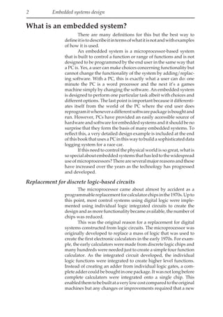
2 Embedded systemsdesign
What is an embedded system?
There are many definitions for this but the best way to
defineitistodescribeitintermsofwhatitisnotandwithexamples
of how it is used.
An embedded system is a microprocessor-based system
that is built to control a function or range of functions and is not
designed to be programmed by the end user in the same way that
a PC is. Yes, a user can make choices concerning functionality but
cannot change the functionality of the system by adding/replac-
ing software. With a PC, this is exactly what a user can do: one
minute the PC is a word processor and the next it’s a games
machine simply by changing the software. An embedded system
is designed to perform one particular task albeit with choices and
different options. The last point is important because it differenti-
ates itself from the world of the PC where the end user does
reprogramitwheneveradifferentsoftwarepackageisboughtand
run. However, PCs have provided an easily accessible source of
hardware and software for embedded systems and it should be no
surprise that they form the basis of many embedded systems. To
reflect this, a very detailed design example is included at the end
of this book that uses a PC in this way to build a sophisticated data
logging system for a race car.
If this need to control the physical world is so great, what is
sospecialaboutembeddedsystemsthathasledtothewidespread
useofmicroprocessors?Thereareseveralmajorreasonsandthese
have increased over the years as the technology has progressed
and developed.
Replacement for discrete logic-based circuits
The microprocessor came about almost by accident as a
programmablereplacementforcalculatorchipsinthe1970s.Upto
this point, most control systems using digital logic were imple-
mented using individual logic integrated circuits to create the
design and as more functionality became available, the number of
chips was reduced.
This was the original reason for a replacement for digital
systems constructed from logic circuits. The microprocessor was
originally developed to replace a mass of logic that was used to
create the first electronic calculators in the early 1970s. For exam-
ple, the early calculators were made from discrete logic chips and
many hundreds were needed just to create a simple four function
calculator. As the integrated circuit developed, the individual
logic functions were integrated to create higher level functions.
Instead of creating an adder from individual logic gates, a com-
plete adder could be bought in one package. It was not long before
complete calculators were integrated onto a single chip. This
enabledthemtobebuiltataverylowcostcomparedtotheoriginal
machines but any changes or improvements required that a new
28.
What is anembedded system? 3
chip be developed. The answer was to build a chip that had some
form of programmable capability within it. Why not build a chip
that took data in, processed it and sent it out again? In this way,
instead of creating new functions by analysing the gate level logic
and modifying it — a very time-consuming process — new
products could be created by changing the program code that
processed the information. Thus the microprocessor was born.
Provide functional upgrades
In the same way that the need to develop new calculator
chips faster and with less cost prompted the development of the
first microprocessors, the need to add or remove functionality
from embedded system designs is even more important. With
much of the system’s functionality encapsulated in the software
that runs in the system, it is possible to change and upgrade
systemsbychangingthesoftwarewhilekeepingthehardwarethe
same. This reduces the cost of production even lower because
many different systems can share the same hardware base.
Insomecases,thisprocessisnotpossibleorworthwhilebut
allows the manufacturer to develop new products far quicker and
faster. Examples of this include timers and control panels for
domestic appliances such as VCRs and televisions.
In other cases, the system can be upgraded to improve
functionality. This is frequently done with machine tools, tel-
ephone switchboards and so on. The key here is that the ability to
add functionality now no longer depends on changing the hard-
ware but can be done by simply changing the software. If the
system is connected to a communications link such as a telephone
or PC network, then the upgrade can be done remotely without
having to physically send out an engineer or technician.
Provide easy maintenance upgrades
The same mechanism that allows new functionality to be
added through reprogramming is also beneficial in allowing bugs
to be solved through changing software. Again it can reduce the
need for expensive repairs and modifications to the hardware.
Improves mechanical performance
Foranyelectromechanicalsystem,theabilitytoofferafiner
degreeofcontrolisimportant.Itcanpreventexcessivemechanical
wear, better control and diagnostics and, in some cases, actually
compensate for mechanical wear and tear. A good example of this
istheenginemanagementsystem.Here,anembeddedmicroproc-
essor controls the fuel mixture and ignition for the engine and will
alter the parameters and timing depending on inputs from the
engine such as temperature, the accelerator position and so on. In
this way, the engine is controlled far more efficiently and can be
configured for different environments like power, torque, fuel
efficiency and so on. As the engine components wear, it can even
29.
4 Embedded systemsdesign
adjust the parameters to compensate accordingly or if they are
dramatically out of spec, flag up the error to the driver or indicate
that servicing is needed.
This level of control is demonstrated by the market in
‘chipped’ engine management units where third party companies
modify the software within the control unit to provide more
power or torque. The differences can range from 10% to nearly
50% for some turbo charged engines! All this from simply chang-
ing a few bytes. Needless to say, this practice may invalidate any
guaranteefromthemanufacturerandmayundulystressandlimit
the engine’s mechanical life. In some cases, it may even infringe
the original manufacturer’s intellectual property rights.
Protection of intellectual property
To retain a competitive edge, it is important to keep the
design knowledge within the company and prevent others from
understandingexactlywhatmakesaproductfunction.Thisknowl-
edge, often referred to as IPR (intellectual property rights), be-
comes all important as markets become more competitive. With a
design that is completely hardware based and built from off-the-
shelf components, it can be difficult to protect the IPR that was
used in its design. All that is needed to do is to take the product,
identifythechipsandhowtheyareconnectedbytracingthetracks
on the circuit board. Some companies actually grind the part
numbers off the integrated circuits to make it harder to reverse
engineer in this way.
With an embedded system, the hardware can be identified
butthesoftwarethatreallysuppliesthesystem’sfunctionalitycan
be hidden and more difficult to analyse. With self-contained
microcontrollers, all that is visible is a plastic package with a few
connections to the outside world. The software is already burnt
intotheon-chipmemoryandiseffectivelyimpossibletoaccess.As
a result, the IPR is much more secure and protected.
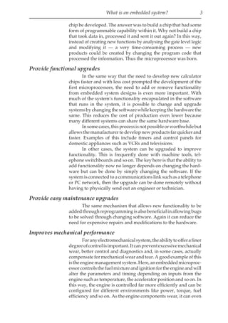
Replacement for analogue circuits
The movement away from the analogue domain towards
digital processing has gathered pace recently with the advent of
high performance and low cost processing.
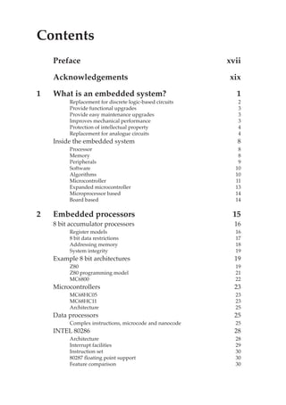
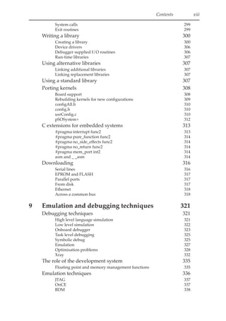
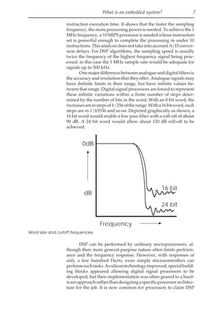
Tounderstandtheadvantagesbehinddigitalsignalprocess-
ing, consider a simple analogue filter. The analogue implementa-
tion is extremely simple compared to its digital equivalent. The
analogue filter works by varying the gain of the operational
amplifier which is determined by the relationship between ri and
rf.
In a system with no frequency component, the capacitor ci
plays no part as its impedance is far greater than that of rf. As the
frequency component increases, the capacitor impedance de-
creases until it is about equal with rf where the effect will be to
reduce the gain of the system. As a result, the amplifier acts as a
30.
What is anembedded system? 5
low pass filter where high frequencies will be filtered out. The
equation shows the relationship where jωis the frequency compo-
nent. These filters are easy to design and are cheap to build. By
making the CR (capacitor-resistor) network more complex, differ-
ent filters can be designed.
y(t)
x(t)
=
r
f
r i 1 + jω r c
1
f
f
y(t)
Output
to
actuator
x(t)
Input
from
sensor
t
y(t)
x(t)
r i
r f
cf
INPUT OUTPUT
The required filtering
The analogue circuit
The mathematical function
Analogue signal processing
x(t)
FIR filter
Finite impulse
response
∑ c(n) x (n-k)
n
k = 0
D/A
A/D y(t)
Low pass
antialiasing
filter
Sampler and
analogue
to
digital
converter
Digital
signal
processing
operation
Digital
to
analogue
converter
Reconstruction
low pass
filter
Analogue
out
Analogue
in
x(n) y(n)
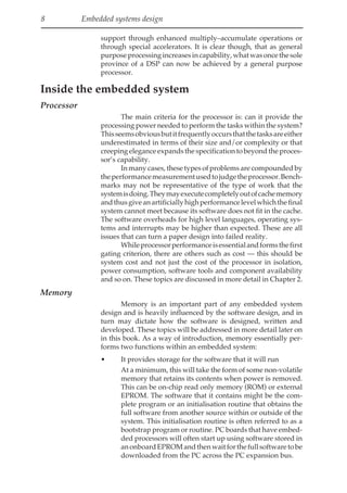
Digital signal processing (DSP)
The digital equivalent is more complex requiring several
electronicstagestoconvertthedata,processitandreconstitutethe
data. The equation appears to be more involved, comprising of a
summation of a range of calculations using sample data multi-
plied by a constant term. These constants take the place of the CR
31.
6 Embedded systemsdesign
components in the analogue system and will define the filter’s
transfer function. With digital designs, it is the tables of coeffi-
cients that are dynamically modified to create the different filter
characteristics.
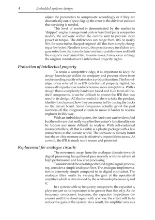
Giventhecomplexityofdigitalprocessing,whythenuseit?
The advantages are many. Digital processing does not suffer from
component ageing, drift or any adjustments which can plague an
analogue design. They have high noise immunity and power
supply rejection and due to the embedded processor can easily
provide self-test features. The ability to dynamically modify the
coefficients and therefore the filter characteristics allows complex
filtersandotherfunctionstobeeasilyimplemented.However,the
processing power needed to complete the ‘multiply–accumulate’
processing of the data does pose some interesting processing
requirements.
N instruction
routine
x(n) x(n+1)
Ts=1/F
A/D
conversion
Data sampling
at frequency Fs
D/A
conversion
Time to execute
one instruction
Fs
Ts
1kHz
10 kHz
100 kHz
1MHz
1 ms
100 µs
10 µs
1 µs
1kHz
10 kHz
100 kHz
1MHz
1 ms
100 µs
10 µs
1 µs
No.of instructions
between two
samples
1000
100
10
1
10000
1000
100
10
1 µs
x(n)
100 µs
y(n)
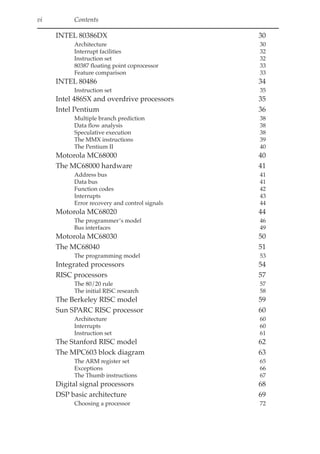
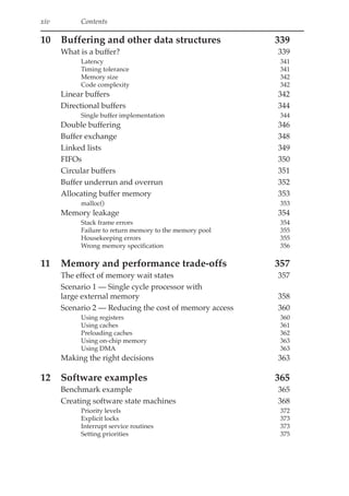
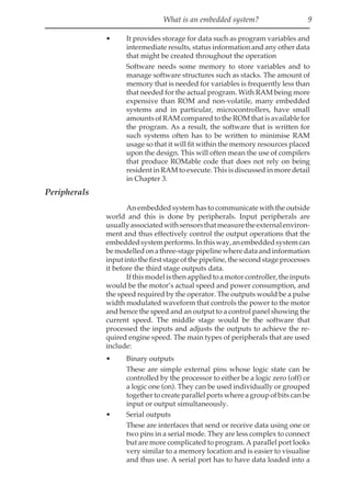
DSP processing requirements
The diagram shows the problem. An analogue signal is
sampled at a frequency fs and is converted by the A/D converter.
This frequency will be first determined by the speed of this
conversion. At every period, ts, there will be a new sample to
process using N instructions. The table shows the relationship
between sampling speed, the number of instructions and the
32.
What is anembedded system? 7
instruction execution time. It shows that the faster the sampling
frequency, the more processing power is needed. To achieve the 1
MHz frequency, a 10 MIPS processor is needed whose instruction
set is powerful enough to complete the processing in under 10
instructions.ThisanalysisdoesnottakeintoaccountA/Dconver-
sion delays. For DSP algorithms, the sampling speed is usually
twice the frequency of the highest frequency signal being proc-
essed: in this case the 1 MHz sample rate would be adequate for
signals up to 500 kHz.
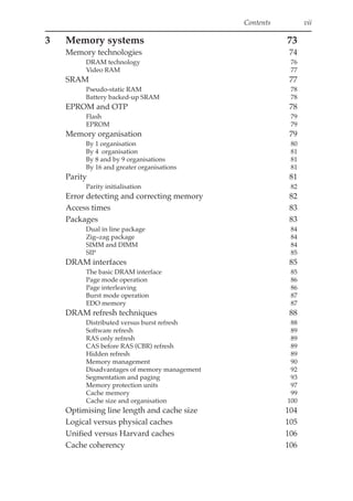
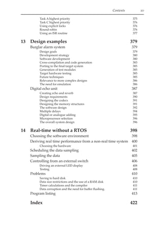
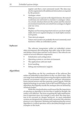
Onemajordifferencebetweenanalogueanddigitalfiltersis
the accuracy and resolution that they offer. Analogue signals may
have definite limits in their range, but have infinite values be-
tween that range. Digital signal processors are forced to represent
these infinite variations within a finite number of steps deter-
mined by the number of bits in the word. With an 8 bit word, the
increasesareinstepsof1/256oftherange.Witha16bitword,such
steps are in 1/65536 and so on. Depicted graphically as shown, a
16 bit word would enable a low pass filter with a roll-off of about
90 dB. A 24 bit word would allow about 120 dB roll-off to be
achieved.
dB
0dB
Frequency
16 bit
24 bit
Word size and cutoff frequencies
DSP can be performed by ordinary microprocessors, al-
though their more general-purpose nature often limits perform-
ance and the frequency response. However, with responses of
only a few hundred Hertz, even simple microcontrollers can
performsuchtasks.Assilicontechnologyimproved,specialbuild-
ing blocks appeared allowing digital signal processors to be
developed, but their implementation was often geared to a hard-
wareapproachratherthandesigningaspecificprocessorarchitec-
ture for the job. It is now common for processors to claim DSP
33.
8 Embedded systemsdesign
support through enhanced multiply–accumulate operations or
through special accelerators. It is clear though, that as general
purposeprocessingincreasesincapability,whatwasoncethesole
province of a DSP can now be achieved by a general purpose
processor.
Inside the embedded system
Processor
The main criteria for the processor is: can it provide the
processing power needed to perform the tasks within the system?
Thisseemsobviousbutitfrequentlyoccursthatthetasksareeither
underestimated in terms of their size and/or complexity or that
creeping elegance expands the specification to beyond the proces-
sor’s capability.
In many cases, these types of problems are compounded by
theperformancemeasurementusedtojudgetheprocessor.Bench-
marks may not be representative of the type of work that the
systemisdoing.Theymayexecutecompletelyoutofcachememory
andthusgiveanartificiallyhighperformancelevelwhichthefinal
system cannot meet because its software does not fit in the cache.
The software overheads for high level languages, operating sys-
tems and interrupts may be higher than expected. These are all
issues that can turn a paper design into failed reality.
Whileprocessorperformanceisessentialandformsthefirst
gating criterion, there are others such as cost — this should be
system cost and not just the cost of the processor in isolation,
power consumption, software tools and component availability
and so on. These topics are discussed in more detail in Chapter 2.
Memory
Memory is an important part of any embedded system
design and is heavily influenced by the software design, and in
turn may dictate how the software is designed, written and
developed. These topics will be addressed in more detail later on
in this book. As a way of introduction, memory essentially per-
forms two functions within an embedded system:
• It provides storage for the software that it will run
At a minimum, this will take the form of some non-volatile
memory that retains its contents when power is removed.
This can be on-chip read only memory (ROM) or external
EPROM. The software that it contains might be the com-
plete program or an initialisation routine that obtains the
full software from another source within or outside of the
system. This initialisation routine is often referred to as a
bootstrap program or routine. PC boards that have embed-
ded processors will often start up using software stored in
anonboardEPROMandthenwaitforthefullsoftwaretobe
downloaded from the PC across the PC expansion bus.
34.
What is anembedded system? 9
• It provides storage for data such as program variables and
intermediate results, status information and any other data
that might be created throughout the operation
Software needs some memory to store variables and to
manage software structures such as stacks. The amount of
memory that is needed for variables is frequently less than
that needed for the actual program. With RAM being more
expensive than ROM and non-volatile, many embedded
systems and in particular, microcontrollers, have small
amounts of RAM compared to the ROM that is available for
the program. As a result, the software that is written for
such systems often has to be written to minimise RAM
usage so that it will fit within the memory resources placed
upon the design. This will often mean the use of compilers
that produce ROMable code that does not rely on being
resident in RAM to execute. This is discussed in more detail
in Chapter 3.
Peripherals
An embedded system has to communicate with the outside
world and this is done by peripherals. Input peripherals are
usuallyassociatedwithsensorsthatmeasuretheexternalenviron-
ment and thus effectively control the output operations that the
embeddedsystemperforms.Inthisway,anembeddedsystemcan
bemodelledonathree-stagepipelinewheredataandinformation
input into the first stage of the pipeline, the second stage processes
it before the third stage outputs data.
Ifthismodelisthenappliedtoamotorcontroller,theinputs
would be the motor’s actual speed and power consumption, and
the speed required by the operator. The outputs would be a pulse
width modulated waveform that controls the power to the motor
and hence the speed and an output to a control panel showing the
current speed. The middle stage would be the software that
processed the inputs and adjusts the outputs to achieve the re-
quired engine speed. The main types of peripherals that are used
include:
• Binary outputs
These are simple external pins whose logic state can be
controlled by the processor to either be a logic zero (off) or
a logic one (on). They can be used individually or grouped
together to create parallel ports where a group of bits can be
input or output simultaneously.
• Serial outputs
These are interfaces that send or receive data using one or
two pins in a serial mode. They are less complex to connect
but are more complicated to program. A parallel port looks
very similar to a memory location and is easier to visualise
and thus use. A serial port has to have data loaded into a
35.
10 Embedded systemsdesign
register and then a start command issued. The data may
also be augmented with additional information as required
by the protocol.
• Analogue values
While processors operate in the digital domain, the natural
world does not and tends to orientate to analogue values.
As a result, interfaces between the system and the external
environment need to be converted from analogue to digital
and vice versa.
• Displays
Displaysarebecomingimportantandcanvaryfromsimple
LEDs and seven segment displays to small alpha-numeric
LCD panels.
• Time derived outputs
Timersandcountersareprobablythemostcommonlyused
functions within an embedded system.
Software
The software components within an embedded system
often encompasses the technology that adds value to the system
and defines what it does and how well it does it. The software can
consist of several different components:
• Initialisation and configuration
• Operating system or run-time environment
• The applications software itself
• Error handling
• Debug and maintenance support.
Algorithms
Algorithms are the key constituents of the software that
makes an embedded system behave in the way that it does. They
can range from mathematical processing through to models of the
external environment which are used to interpret information
from external sensors and thus generate control signals. With the
digital technology in use today such as MP3 and DVD players, the
algorithms that digitally encode the analogue data are defined by
standards bodies.
While this standardisation could mean that the importance
of selecting an algorithm is far less than it might be thought, the
reality is far different. The focus on getting the right implementa-
tion is important since, for example, it may allow the same func-
tion to be executed on cheaper hardware. As most embedded
systems are designed to be commercially successful, this selection
process is very important. Defining and implementing the correct
algorithm is a critical operation and is described through several
examples in this book.
36.
What is anembedded system? 11
Examples
This section will go through some example embedded
systems and briefly outline the type of functionality that each
offers.
Microcontroller
Microcontrollers can be considered as self-contained sys-
tems with a processor, memory and peripherals so that in many
cases all that is needed to use them within an embedded system is
to add software. The processors are usually based on 8 bit stack-
based architectures such as the MC6800 family. There are 4 bit
versions available such as the National COP series which further
reduce the processing power and reduce cost even further. These
are limited in their functionality but their low cost has meant that
they are used in many obscure applications. Microcontrollers are
usually available in several forms:
• Devices for prototyping or low volume production runs
These devices use non-volatile memory to allow the soft-
ware to be downloaded and returned in the device. UV
erasable EPROM used to be the favourite but EEPROM is
also gaining favour. Some microcontrollers used a special
package with a piggyback socket on top of the package to
allow an external EPROM to be plugged in for prototyping.
This memory technology replaces the ROM on the chip
allowing software to be downloaded and debugged. The
device can be reprogrammed as needed until the software
reaches its final release version.
The use of non-volatile memory also makes these devices
suitable for low volume production runs or where the
software may need customisation and thus preventing
moving to a ROMed version.
These devices are sometimes referred to as umbrella de-
vices with a single device capable of providing prototyping
support for a range of other controllers in the family.
• Devices for low to medium volume production runs
In the mid-1980s, a derivative of the prototype device
appeared on the market called the one time programmable
or OTP. These devices use EPROM instead of the ROM but
instead of using the ceramic package with a window to
allow the device to be erased, it was packaged in a cheaper
plastic pack and thus was only capable of programming a
single time — hence the name. These devices are cheaper
than the prototype versions but still have the programming
disadvantage. However, their lower cost has made them a
suitable alternative to producing a ROM device. For low to
medium production quantities, they are cost effective and
offer the ability to customise software as necessary.
37.
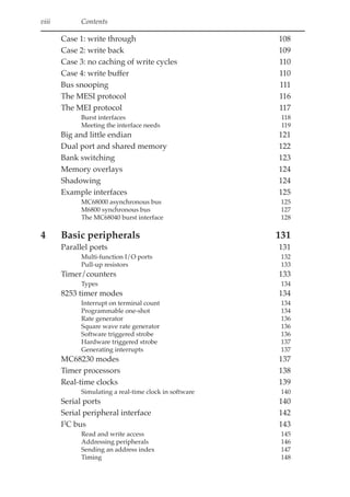
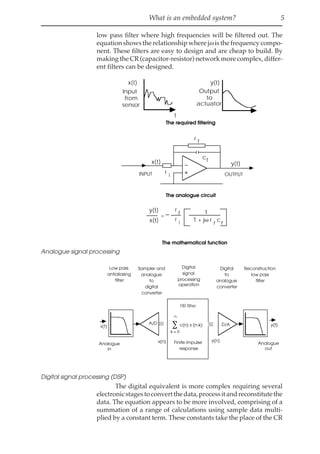
12 Embedded systemsdesign
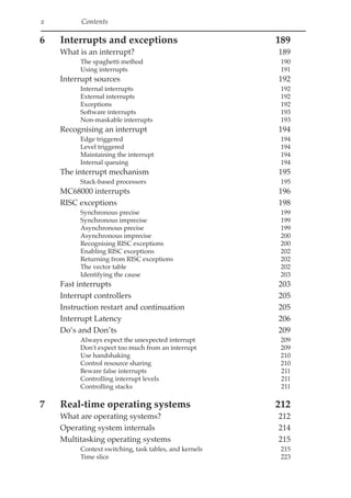
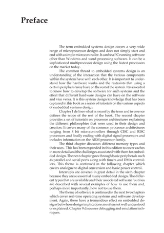
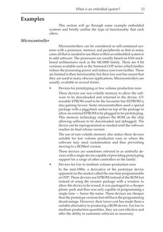
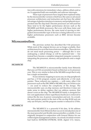
4144 bytes
EPROM
176 bytes
RAM
240 bytes Boot
ROM
HC05 processor
core
Clock
Watch
dog Baud rate
generator
16 bit timer
Port
A
Port
B
Port
C
Port
D
SCI
SPI
Internal bus
Example microcontroller (Motorola MC68HC705C4A)
• Devices for high volume production runs
For high volumes, microcontrollers can be built already
programmed with software in the ROM. To do this a
customer supplies the software to the manufacturer who
then creates the masks necessary to create the ROM in the
device. This process is normally done on partly processed
silicon wafers to reduce the turnaround time. The advan-
tage for the customer is that the costs are much lower than
using prototyping or OTP parts and there is no program-
mingtimeoroverheadinvolved.Thedownsideisthatthere
is usually a minimum order based on the number of chips
thatawaferbatchcanproduceandanupfrontmaskcharge.
The other major point is that once in ROM, the software
cannot be changed and therefore customisation or bug
fixing would have to wait until the next order or involve
scrapping all the devices that have been made. It is possible
tooffersomecustomisationbyincludingdifferentsoftware
modules and selecting the required ones on the basis of a
value read into the device from an external port but this
does consume memory which can increase the costs. Some
controllerscanprovidesomeRAMthatcanbeusedtopatch
the ROM without the need for a new mask set.
38.
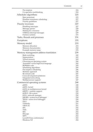
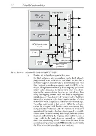
What is anembedded system? 13
MC68HC
705
MC68HC
705
EPROM
prototyping
OTP External
EPROM
(no chip)
External
EPROM
(with chip)
Prototype microcontrollers
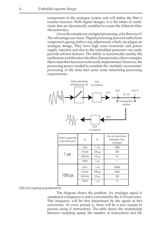
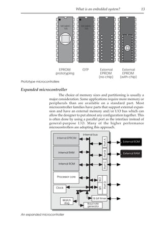
Expanded microcontroller
The choice of memory sizes and partitioning is usually a
major consideration. Some applications require more memory or
peripherals than are available on a standard part. Most
microcontroller families have parts that support external expan-
sion and have an external memory and/or I/O bus which can
allow the designer to put almost any configuration together. This
is often done by using a parallel port as the interface instead of
general-purpose I/O. Many of the higher performance
microcontrollers are adopting this approach.
Internal EPROM
Internal RAM
Internal ROM
Processor core
Clock
Watch
dog Baud rate
generator
16 bit timer
Port
A
Port
B
Port
C
Port
D
SCI
SPI
Internal bus
External ROM
External RAM
An expanded microcontroller
39.
14 Embedded systemsdesign
In the example shown on the previous page, the
microcontroller has an expanded mode that allows the parallel
ports A and B to be used as byte wide interfaces to external RAM
and ROM. In this type of configuration, some microcontrollers
disable access to the internal memory while others still allow it.
Microprocessor based
Microprocessor-based embedded systems originally took
existing general-purpose processors such as the MC6800 and 8080
devices and constructed systems around them using external
peripherals and memory. The use of processors in the PC market
continued to provide a series of faster and faster processors such
as the MC68020, MC68030 and MC68040 devices from Motorola
and the 80286, 80386, 80486 and Pentium devices from Intel. These
CISC architectures have been complemented with RISC proces-
sors such as the PowerPC, MIPS and others. These systems offer
more performance than is usually available from a traditional
microcontroller.
However, this is beginning to change. There has been the
development of integrated microprocessors where the processor
is combined with peripherals such as parallel and serial ports,
DMAcontrollersandinterfacelogictocreatedevicesthataremore
suitable for embedded systems by reducing the hardware design
task and costs. As a result, there has been almost a parallel
development of these integrated processors along with the desk-
top processors. Typically, the integrated processor will use a
processor generation that is one behind the current generation.
The reason is dependent on silicon technology and cost. By using
thepreviousgenerationwhichissmaller,itfreesupsiliconareaon
the die to add the peripherals and so on.
Board based
So far, the types of embedded systems that we have consid-
ered have assumed that the hardware needs to be designed, built
and debugged. An alternative is to use hardware that has already
been built and tested such as board-based systems as provided by
PCs and through international board standards such as VMEbus.
The main advantage is the reduced work load and the availability
of ported software that can simply be utilised with very little
effort. The disadvantages are higher cost and in some cases
restrictions in the functionality that is available.
40.
Embedded processors 15
2Embedded processors
The development of processors for embedded system de-
sign has essentially followed the development of microprocessors
as a whole. The processor development has provided the process-
ing heart for architecture which combined with the right software
and hardware peripherals has become an embedded design. With
the advent of better fabrication technology supporting higher
transistor counts and lower power dissipation, the processor core
has been integrated with peripherals and memory to provide
standalone microcontrollers or integrated processors that only
need the addition of external memory to provide a complete
hardware system suitable for embedded design. The scope of this
chapter is to explain the strengths and weaknesses of various
architectures to provide a good understanding of the trade-offs
involved in choosing and exploiting a processor family.
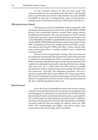
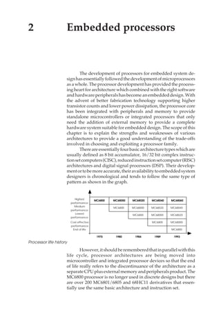
Thereareessentiallyfourbasicarchitecturetypeswhichare
usually defined as 8 bit accumulator, 16/32 bit complex instruc-
tionsetcomputers(CISC),reducedinstructionsetcomputer(RISC)
architectures and digital signal processors (DSP). Their develop-
mentortobemoreaccurate,theiravailabilitytoembeddedsystem
designers is chronological and tends to follow the same type of
pattern as shown in the graph.
MC6800
MC6800
MC6800
MC6800
MC6800
MC68000
MC68000
MC68000
MC68000
MC68020
MC68020
MC68020
MC68040
MC68040
MC68060
1975 1980 1984 1989 1993
Highest
performance
Medium
performance
Lowest
performance
Cost-effective
performance
End of life
Processor life history
However,itshouldberememberedthatinparallelwiththis
life cycle, processor architectures are being moved into
microcontroller and integrated processor devices so that the end
of life really refers to the discontinuance of the architecture as a
separateCPUplusexternalmemoryandperipheralsproduct.The
MC6800 processor is no longer used in discrete designs but there
are over 200 MC6801/6805 and 68HC11 derivatives that essen-
tially use the same basic architecture and instruction set.
41.
16 Embedded systemsdesign
8 bit accumulator processors
This category of processor first appeared in the mid-1970s
as the first microprocessors. Devices such as the 8080 from Intel
and the MC6800 from Motorola started the microprocessor revo-
lution. They provided about 1 MIP of performance and were at
their introduction the fastest processors available.
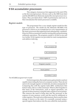
Register models
The programmer has a very simple register model for this
type of processor. The model for the Motorola MC6800 8 bit
processor is shown as an example but it is very representative of
the many processors that appeared (and subsequently vanished).
Ithastwo8bitaccumulatorsusedforstoringdataandperforming
arithmetic operations. The program counter is 16 bits in size and
two further 16 bit registers are provided for stack manipulations
and address indexing.
7 0
15
Accumulator A
Accumulator B
Index register X
Program counter
Stack pointer
Condition code
The MC6800 programmer's model
Onfirstinspection,themodelseemsquiteprimitiveandnot
capable of providing the basis of a computer system. There do not
seem to be enough registers to hold data, let alone manipulate it!
Comparing this with the register laden RISC architectures that
feature today, this is a valid conclusion. What is often forgotten is
that many of the instructions, such as logical operations, can
operateondirectmemoryusingtheindexregistertoactaspointer.
This removes the need to bring data into the processor at the
expense of extra memory cycles and the need for additional or
widerregisters.Themainareawithinmemorythatisusedfordata
storage is known as the stack. It is normally accessed using a
special register that indexes into the area called the stack pointer.
42.
Embedded processors 17
Thisisusedtoprovidelocaldatastorageforprogramsandtostore
informationfortheprocessorsuchasreturnaddressesforsubrou-
tinejumps and interrupts.
The stack pointer provides additional storage for the pro-
grammer: it is used to store data like return addresses for subrou-
tine calls and provides additional variable storage using a PUSH/
POP mechanism. Data is PUSHed onto the stack to store it, and
POPed off to retrieve it. Providing the programmer can track
where the data resides in these stack frames, it offers a good
replacement for the missing registers.
8 bit data restrictions
An 8 bit data value can provide an unsigned resolution of
only 256 bits, which makes it unsuitable for applications where a
higher resolution is needed. In these cases, such as financial,
arithmetic, high precision servo control systems, the obvious
solution is to increase the data size to 16 bits. This would give a
resolution of 65536 — an obvious improvement. This may be
acceptable for a control system but is still not good enough for a
dataprocessingprogram,wherea32bitdatavaluemayhavetobe
defined to provide sufficient integer range. While there is no
difficulty with storing 8, 16, 32 or even 64 bits in external memory,
even though this requires multiple bus accesses, it does prevent
the direct manipulation of data through the instruction set.
However, due to the register model, data larger than 8 bits
cannot use the standard arithmetic instructions applicable to 8 bit
data stored in the accumulator. This means that even a simple 16
bit addition or multiplication has to be carried out as a series of
instructions using the 8 bit model. This reduces the overall effi-
ciency of the architecture.
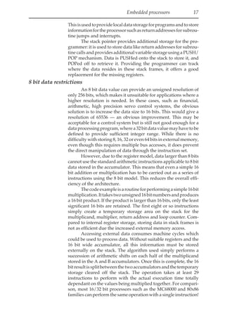
Thecodeexampleisaroutineforperformingasimple16bit
multiplication.Ittakestwounsigned16bitnumbersandproduces
a 16 bit product. If the product is larger than 16 bits, only the least
significant 16 bits are retained. The first eight or so instructions
simply create a temporary storage area on the stack for the
multiplicand, multiplier, return address and loop counter. Com-
pared to internal register storage, storing data in stack frames is
not as efficient due the increased external memory access.
Accessing external data consumes machine cycles which
could be used to process data. Without suitable registers and the
16 bit wide accumulator, all this information must be stored
externally on the stack. The algorithm used simply performs a
succession of arithmetic shifts on each half of the multiplicand
stored in the A and B accumulators. Once this is complete, the 16
bitresultissplitbetweenthetwoaccumulatorsandthetemporary
storage cleared off the stack. The operation takes at least 29
instructions to perform with the actual execution time totally
dependant on the values being multiplied together. For compari-
son, most 16/32 bit processors such as the MC68000 and 80x86
families can perform the same operation with a single instruction!
43.
18 Embedded systemsdesign
MULT16 LDX #5 CLEAR WORKING REGISTERS
CLR A
LP1 STA A U-1,X
DEX
BNE LP1
LDX #16 INITIAL SHIFT COUNTER
LP2 LDA A Y+1 GET Y(LSBIT)
AND A #1
TAB SAVE Y(LSBIT) IN ACCB
EOR A FF CHECK TO SEE IF YOU ADD
BEQ SHIFT OR SUBTRACT
TST B
BEQ ADD
LDA A U+1
LDA B U
SUB A XX+1
SBC B XX
STA A U+1
STA B U
BRA SHIFT NOW GOTO SHIFT ROUTINE
ADD LDA A U+1
LDA B U
ADD A XX+1
ADC B XX
STA A U+1
STA B U
SHIFT CLR FF SHIFT ROUTINE
ROR Y
ROR Y+1
ROL FF
ASR U
ROR U+1
ROR U+2
ROR U+3
DEX
BNE LP2
RTS FINISH SUBROUTINE
END
M6800 code for a 16 bit by 16 bit multiply
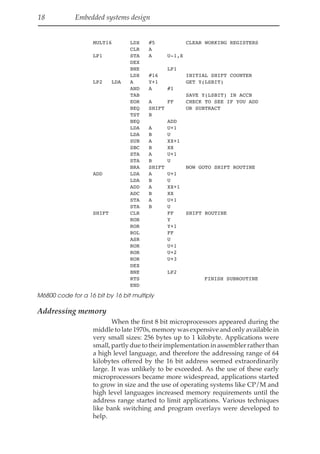
Addressing memory
When the first 8 bit microprocessors appeared during the
middle to late 1970s, memory was expensive and only available in
very small sizes: 256 bytes up to 1 kilobyte. Applications were
small, partly due to their implementation in assembler rather than
a high level language, and therefore the addressing range of 64
kilobytes offered by the 16 bit address seemed extraordinarily
large. It was unlikely to be exceeded. As the use of these early
microprocessors became more widespread, applications started
to grow in size and the use of operating systems like CP/M and
high level languages increased memory requirements until the
address range started to limit applications. Various techniques
like bank switching and program overlays were developed to
help.
44.
Embedded processors 19
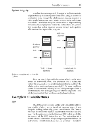
Systemintegrity
Another disadvantage with this type of architecture is its
unpredictability in handling error conditions. A bug in a software
application could corrupt the whole system, causing a system to
either crash, hang up or, even worse, perform some unforeseen
operations. The reasons are quite simple: there is no partitioning
between data and programs within the architecture. An applica-
tion can update a data structure using a corrupt index pointer
which overwrites a part of its program.
start
finish
Address
pointer
New
data
start
finish
System
memory
Address
pointer
System
Memory
New
data
Valid pointer
address
Invalid pointer
address
System corruption via an invalid
pointer
Data are simply bytes of information which can be inter-
preted as instruction codes. The processor calls a subroutine
withinthisarea,startstoexecutethedataascodeandsuddenlythe
whole system starts performing erratically! On some machines,
certain undocumented code sequences could put the processor in
atestmodeandstartcyclingthroughtheaddressrangesetc.These
attributes restricted their use to non-critical applications.
Example 8 bit architectures
Z80
TheZ80microprocessorisan8bitCPUwitha16bitaddress
bus capable of direct access to 64k of memory space. It was
designedbyZilogandrapidlygainedalotofinterest.TheZ80was
based on the Intel 8080 but has an extended instruction set and
many hardware improvements. It can run 8080 code if needed by
its support of the 8080 instruction set. The instruction set is
essential based around an 8 bit op code giving a maximum of 256
instructions. The 158 instructions that are specified — the others
45.
20 Embedded systemsdesign
are reserved — include 78 instructions from the 8080. The instruc-
tion set supports the use of extension bytes to encode additional
information. In terms of processing power, it offered about 1 MIP
at 4 MHz clock speed with a minimum instruction time of 1 µs and
a maximum instruction time of 5.75 µs.
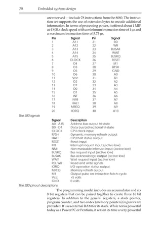
Pin Signal Pin Signal
1 A11 21 RD
2 A12 22 WR
3 A13 23 BUSAK
4 A14 24 WAIT
5 A15 25 BUSRQ
6 CLOCK 26 RESET
7 D4 27 M1
8 D3 28 RFSH
9 D5 29 GND
10 D6 30 A0
11 Vcc 31 A1
12 D2 32 A2
13 D7 33 A3
14 D0 34 A4
15 D1 35 A5
16 INT 36 A6
17 NMI 37 A7
18 HALT 38 A8
19 MREQ 39 A9
20 IORQ 40 A10
The Z80 signals
Signal Description
A0 - A15 Address bus output tri-state
D0 - D7 Data bus bidirectional tri-state
CLOCK CPU clock input
RFSH Dynamic memory refresh output
HALT CPU halt status output
RESET Reset input
INT Interrupt request input (active low)
NMI Non-maskable interrupt input (active low)
BUSRQ Bus request input (active low)
BUSAK Bus acknowledge output (active low)
WAIT Wait request input (active low)
RD, WR Read and write signals
IORQ I/O operation status output
MREQ Memory refresh output
M1 Output pulse on instruction fetch cycle
Vcc +5 volts
GND 0 volts
The Z80 pinout descriptions
The programming model includes an accumulator and six
8 bit registers that can be paired together to create three 16 bit
registers. In addition to the general registers, a stack pointer,
program counter, and two index (memory pointers) registers are
provided.ItusesexternalRAMforitsstack.Whilenotaspowerful
today as a PowerPC or Pentium, it was in its time a very powerful
46.
Embedded processors 21
processorandwasusedinmanyoftheearlyhomecomputerssuch
asthe Amstrad CPC series. It was also used in many embedded
designs partly because of its improved performance and also for
its built-in refresh circuitry for DRAMs. This circuitry greatly
simplified the external glue logic that was needed with DRAMs.
The Z80 was originally packaged in a 40 pin DIP package
and ran at 2.5 and 4 MHz. Since then other packages and speeds
have become available including low power CMOS versions —
theoriginalwasmadeinNMOSanddissipatedabout1watt.Zilog
now use the processor as a core within its range of Z800
microcontrollerswithvariousconfigurationsofon-chipRAMand
EPROM.
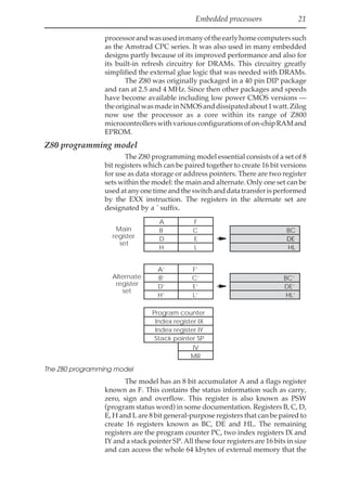
Z80 programming model
The Z80 programming model essential consists of a set of 8
bit registers which can be paired together to create 16 bit versions
for use as data storage or address pointers. There are two register
sets within the model: the main and alternate. Only one set can be
usedatanyonetimeandtheswitchanddatatransferisperformed
by the EXX instruction. The registers in the alternate set are
designated by a ´ suffix.
BC
DE
HL
A F
B C
D E
H L
A’ F’
B’ C’
D’ E’
H’ L’
Program counter
PC
Index register IX
Index register IY
Stack pointer SP
IV
MR
Main
register
set
Alternate
register
set
BC’
DE’
HL’
The Z80 programming model
The model has an 8 bit accumulator A and a flags register
known as F. This contains the status information such as carry,
zero, sign and overflow. This register is also known as PSW
(program status word) in some documentation. Registers B, C, D,
E, H and L are 8 bit general-purpose registers that can be paired to
create 16 registers known as BC, DE and HL. The remaining
registers are the program counter PC, two index registers IX and
IY and a stack pointer SP. All these four registers are 16 bits in size
and can access the whole 64 kbytes of external memory that the
47.
22 Embedded systemsdesign
Z80 can access. There are two additional registers IV and MR
which are the interrupt vector and the memory refresh registers.
The IV register is used in the interrupt handling mode 2 to point
to the required software routine to process the interrupt. In mode
1, the interrupt vector is supplied via the external data bus. The
memory refresh register is used to control the on-chip DRAM
refresh circuitry.
Unlike the MC6800, the Z80 does not use memory mapped
I/O and instead uses the idea of ports, just like the 8080. The lower
8 bits of the address bus are used along with the IORQ signal to
access any external peripherals. The IORQ signal is used to differ-
entiatetheaccessfromanormalmemorycycle.TheseI/Oaccesses
are similar from a hardware perspective to a memory cycle but
only occur when an I/O port instruction (IN, OUT) is executed. In
some respects, this is similar to the RISC idea of load and store
instructionstobringinformationintotheprocessor,processitand
then write out the data. This system gives 255 ports and is usually
sufficient for most embedded designs.
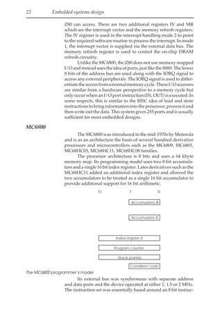
MC6800
The MC6800 was introduced in the mid-1970s by Motorola
and is as an architecture the basis of several hundred derivative
processors and microcontrollers such as the MC6809, MC6801,
MC68HC05, MC68HC11, MC68HC08 families.
The processor architecture is 8 bits and uses a 64 kbyte
memory map. Its programming model uses two 8 bit accumula-
tors and a single 16 bit index register. Later derivatives such as the
MC68HC11 added an additional index register and allowed the
two accumulators to be treated as a single 16 bit accumulator to
provide additional support for 16 bit arithmetic.
7 0
15
Accumulator A
Accumulator B
Index register X
Program counter
Stack pointer
Condition code
The MC6800 programmer‘s model
Its external bus was synchronous with separate address
and data ports and the device operated at either 1, 1.5 or 2 MHz.
The instruction set was essentially based around an 8 bit instruc-
48.
Embedded processors 23
tionwith extensions for immediate values, address offsets and so
on. It supported both non-maskable and software interrupts.
These type of processors have largely been replaced today
by the microcontroller versions which have the same or advanced
processor architectures and instruction sets but have the added
advantageofgluelessinterfacestomemoryandperipheralsincor-
porated onto the chip itself. Discrete processors are still used but
these tend to be the higher performance devices such as the
MC68000 and 80x86 processors. But even with these faster and
higher performance devices, the same trend of moving to inte-
grated microcontroller type of devices is being followed as even
higher performance processors such as RISC devices become
available.
Microcontrollers
The previous section has described the 8 bit processors.
While most of the original devices are no longer available, their
architecturesliveonintheformofmicrocontrollers.Thesedevices
do not need much processing power — although this is now
undergoing a radical change as will be explained later — but
instead have become a complete integrated computer system by
integrating the processor, memory and peripherals onto a single
chip.
MC68HC05
The MC68HC05 is microcontroller family from Motorola
that uses an 8 bit accumulator-based architecture as its processor
core. This is very similar to that of the MC6800 except that it only
has a single accumulator.
It uses memory mapping to access any on-chip peripherals
and has a 13 bit program counter and effectively a 6 bit stack
pointer. These reduced size registers — with many other 8 bit
processors such as the Z80/8080 or MC6800, they are 16 bits is size
— are used to reduce the complexity of the design. The
microcontroller uses on-chip memory and therefore it does not
make sense to define registers that can address memory that
doesn’t exist on the chip. The MC68HC05 family is designed for
low cost applications where superfluous hardware is removed to
reduce the die size, its power consumption and cost. As a result,
the stack pointer points to the start of the on-chip RAM and can
only use 64 bytes, and the program counter is reduced to 13 bits.
MC68HC11
The MC68HC11 is a powerful 8 bit data, 16 bit address
microcontroller from Motorola that was on its introduction one of
the most powerful and flexible microcontrollers available. It was
originally designed in conjunction with General Motors for use
withinenginemanagementsystems.Asaresult,itsinitialversions
had built-in EEPROM/OTPROM, RAM, digital I/O, timers,
49.
24 Embedded systemsdesign
4144 bytes
EPROM
176 bytes
RAM
240 bytes Boot
ROM
HC05 processor
core
Clock
Watch
dog Baud rate
generator
16 bit timer
Port
A
Port
B
Port
C
Port
D
SCI
SPI
Internal bus
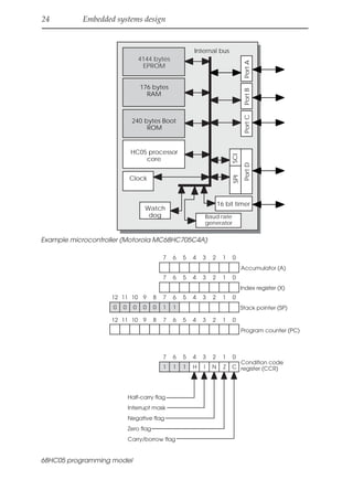
Example microcontroller (Motorola MC68HC705C4A)
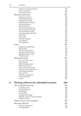
7 6 5 4 3 2 1 0
7 6 5 4 3 2 1 0
7 6 5 4 3 2 1 0
11 10 9 8
12
7 6 5 4 3 2 1 0
11 10 9 8
12
1 1
0 0 0 0
0
7 6 5 4 3 2 1 0
1 1 1 H I N Z C
Accumulator (A)
Index register (X)
Stack pointer (SP)
Program counter (PC)
Condition code
register (CCR)
Half-carry flag
Interrupt mask
Negative flag
Zero flag
Carry/borrow flag
68HC05 programming model
Welcome to OurBookstore - The Ultimate Destination for Book Lovers
Are you passionate about books and eager to explore new worlds of
knowledge? At our website, we offer a vast collection of books that
cater to every interest and age group. From classic literature to
specialized publications, self-help books, and children’s stories, we
have it all! Each book is a gateway to new adventures, helping you
expand your knowledge and nourish your soul
Experience Convenient and Enjoyable Book Shopping Our website is more
than just an online bookstore—it’s a bridge connecting readers to the
timeless values of culture and wisdom. With a sleek and user-friendly
interface and a smart search system, you can find your favorite books
quickly and easily. Enjoy special promotions, fast home delivery, and
a seamless shopping experience that saves you time and enhances your
love for reading.
Let us accompany you on the journey of exploring knowledge and
personal growth!
ebookgate.com