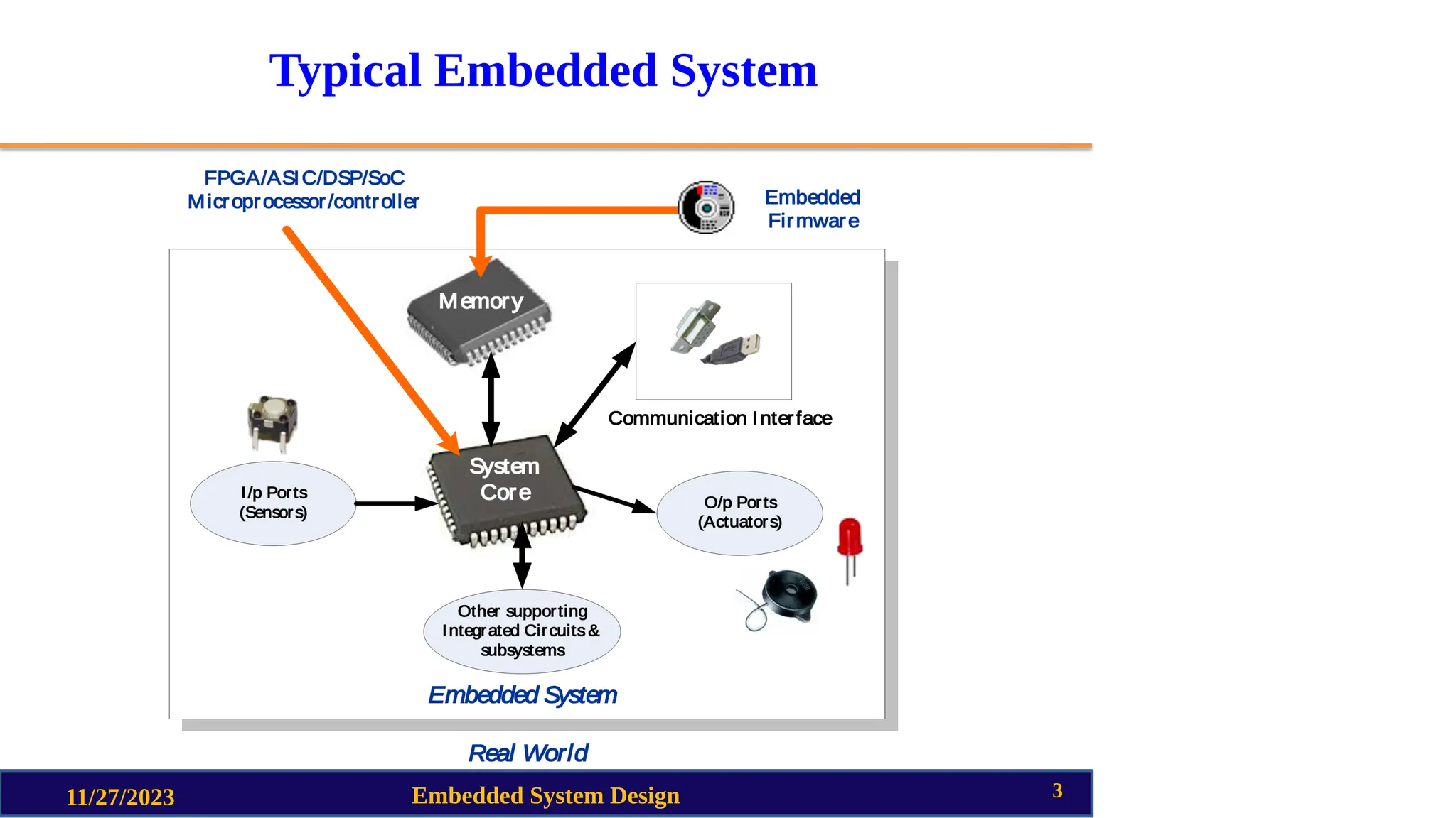
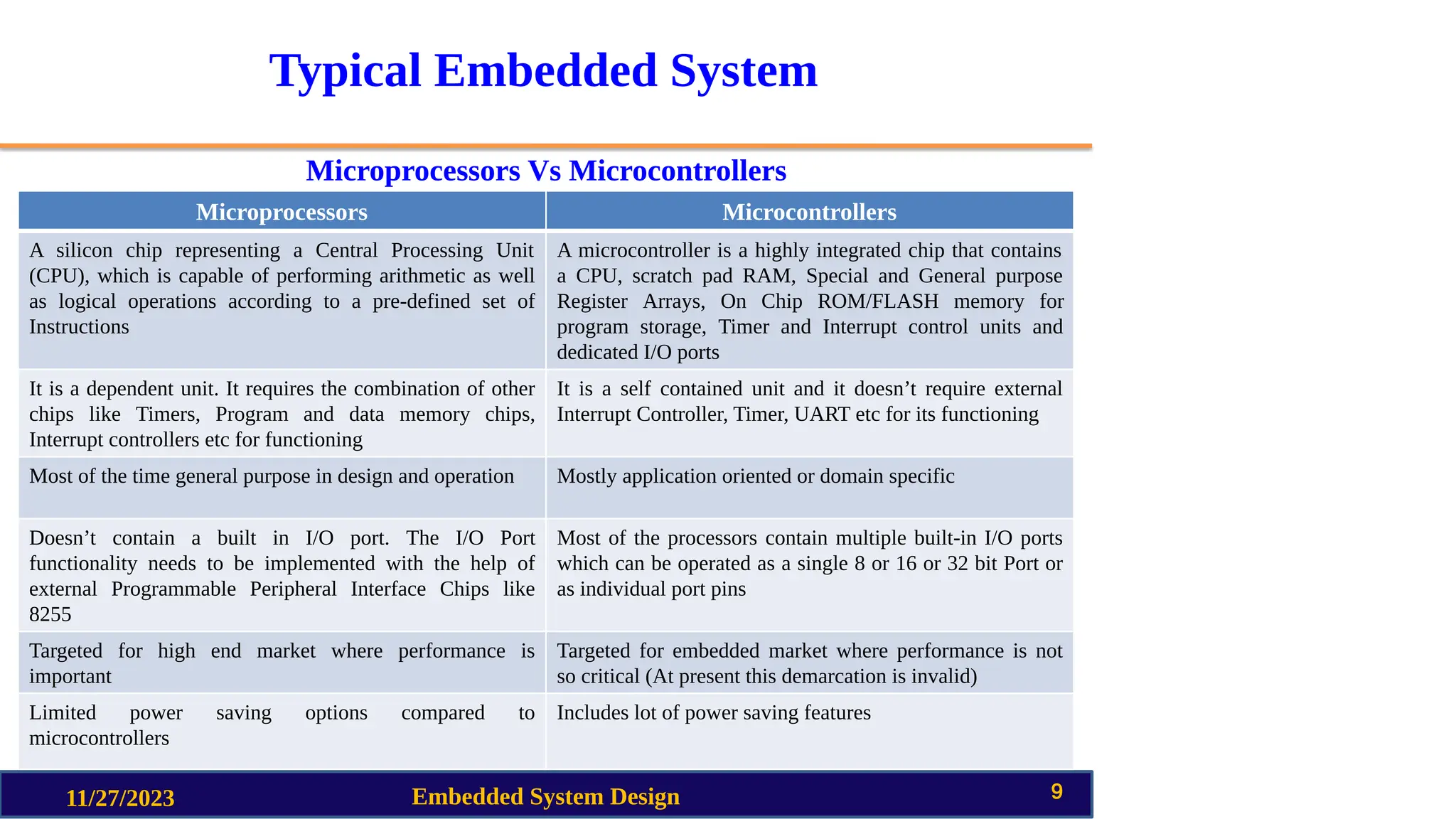
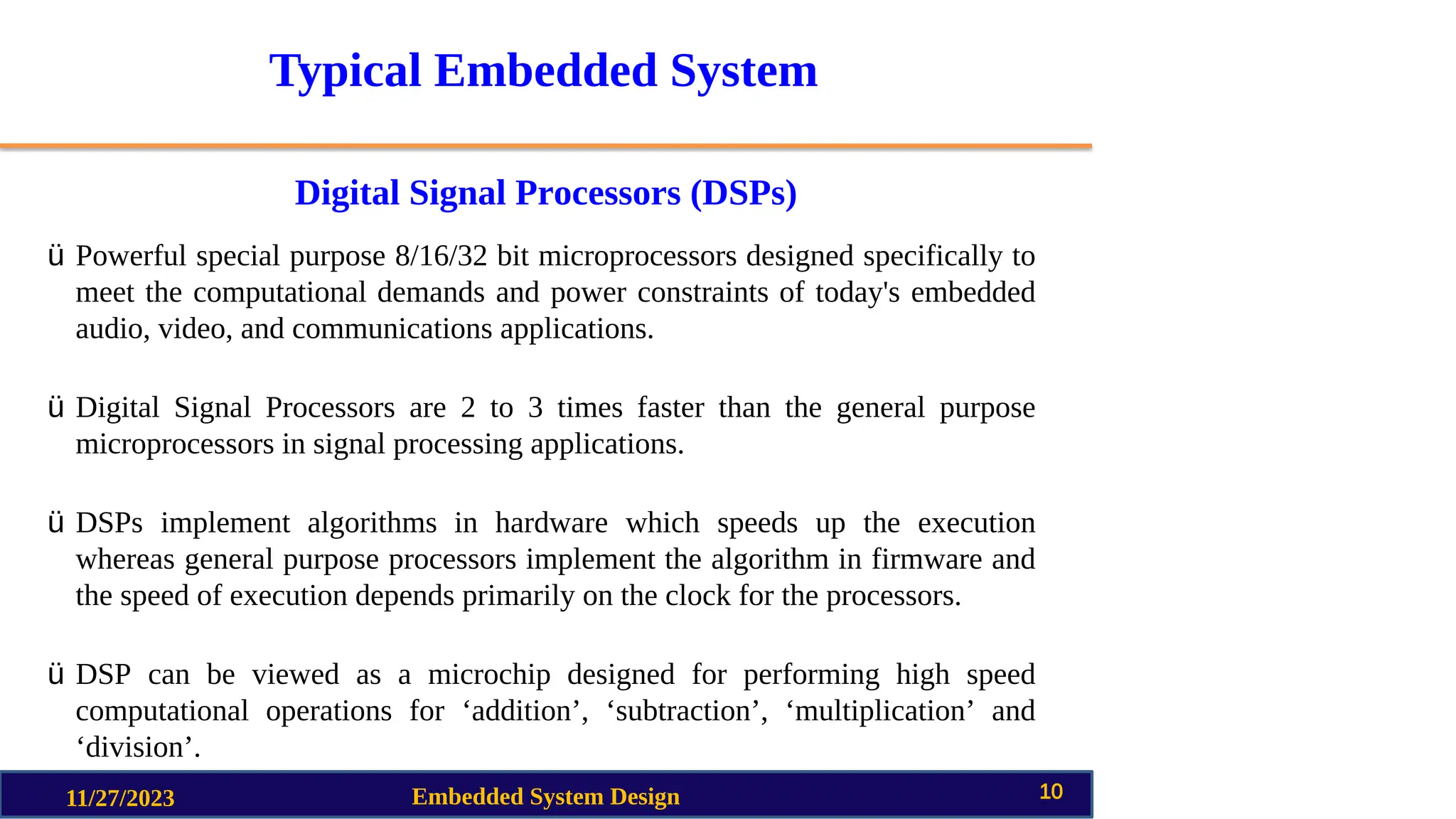
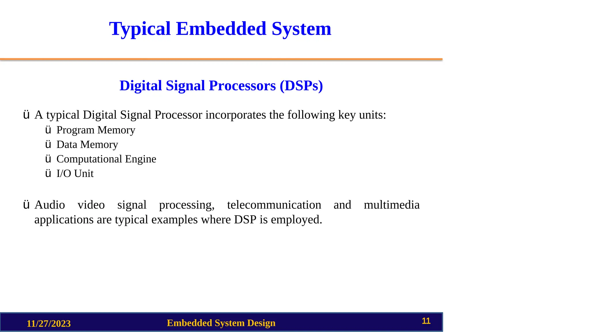
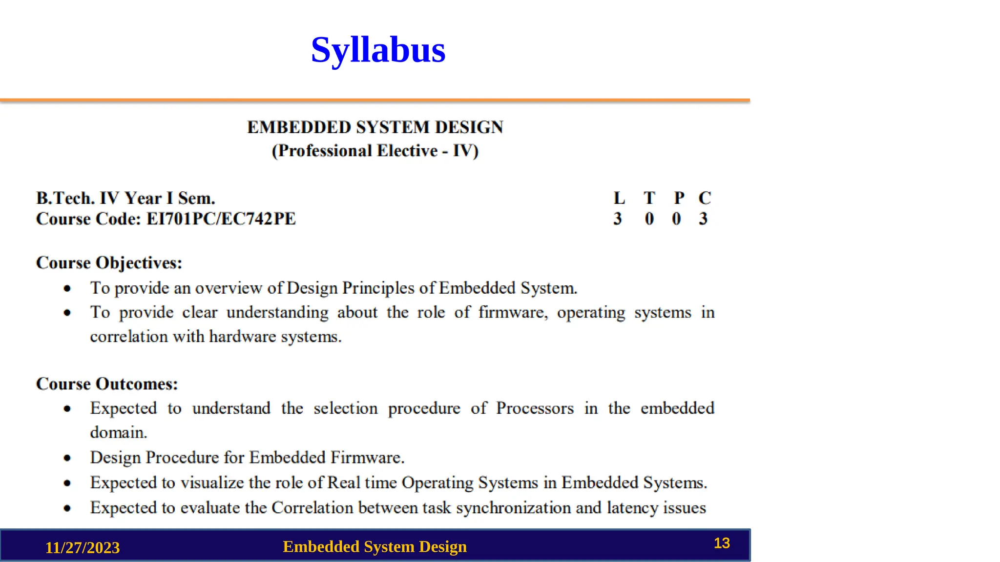
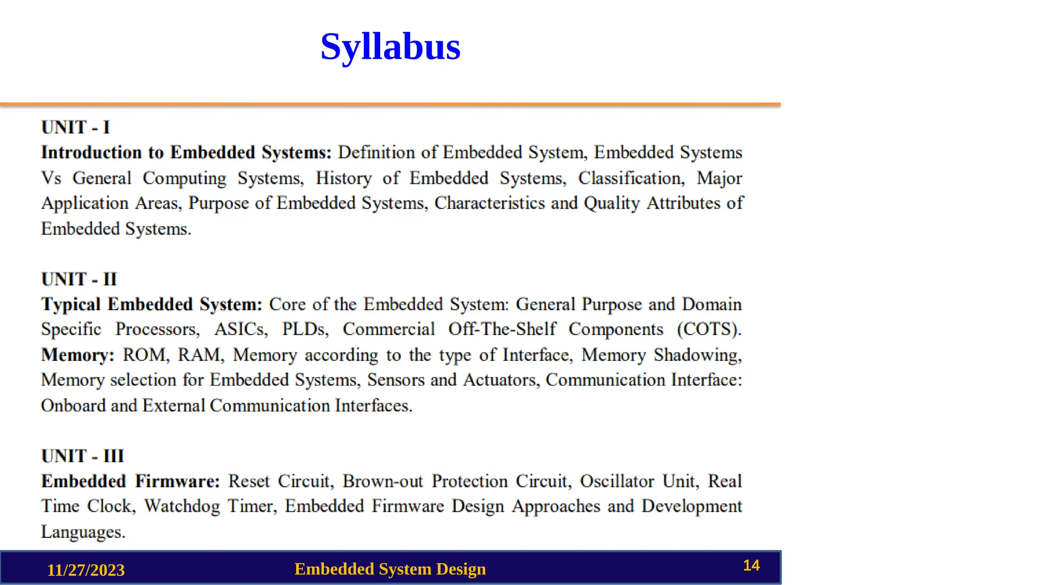
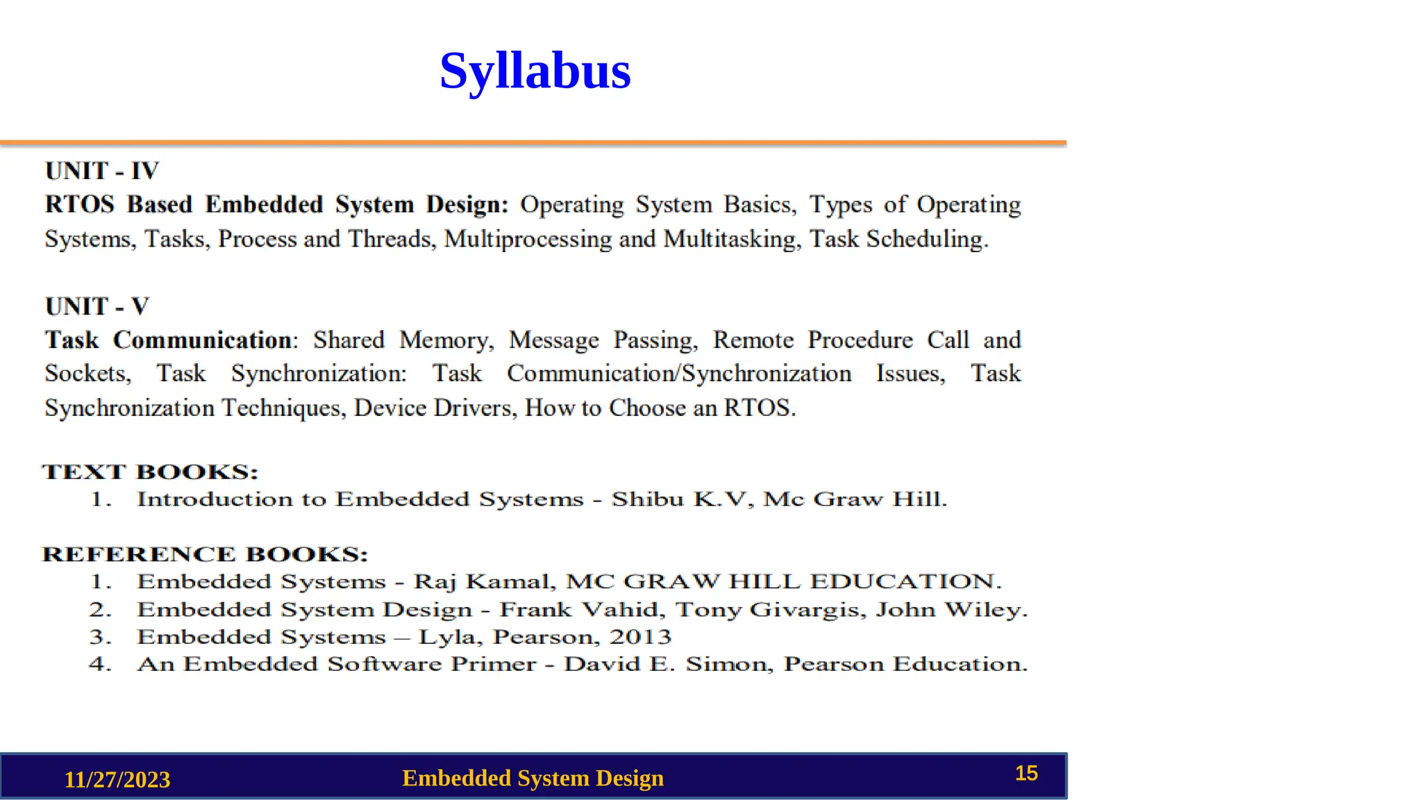
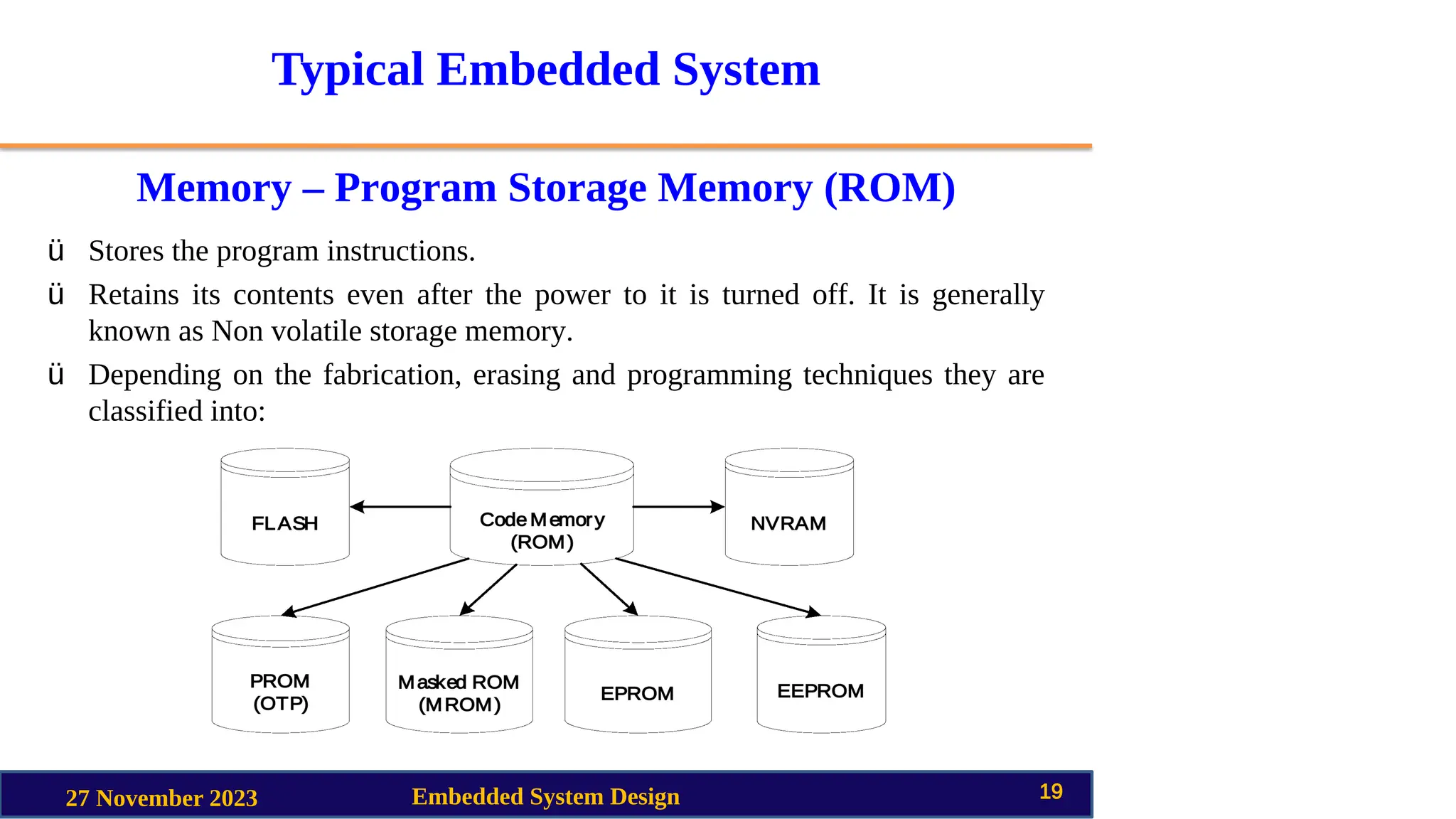
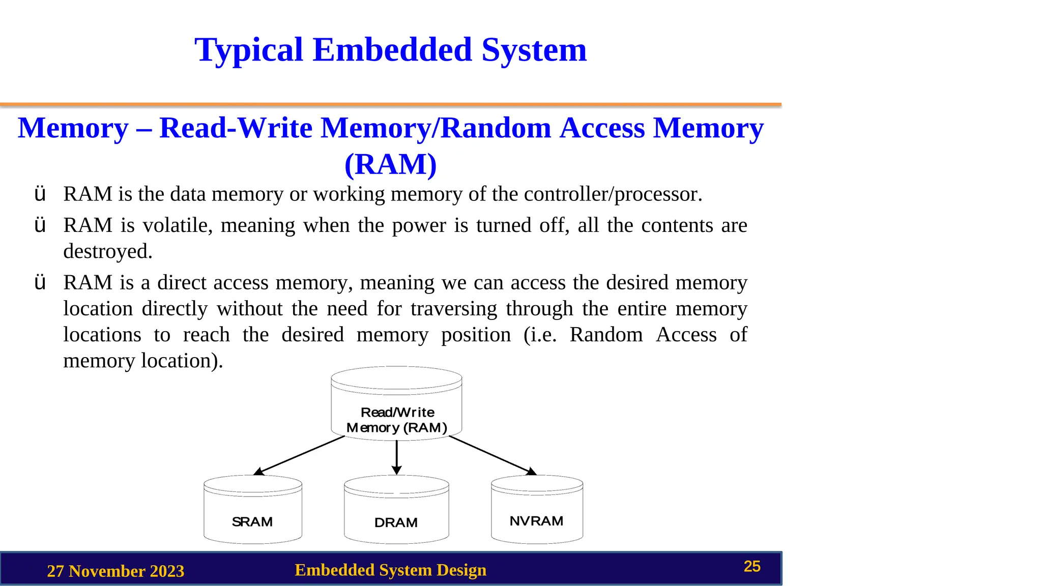
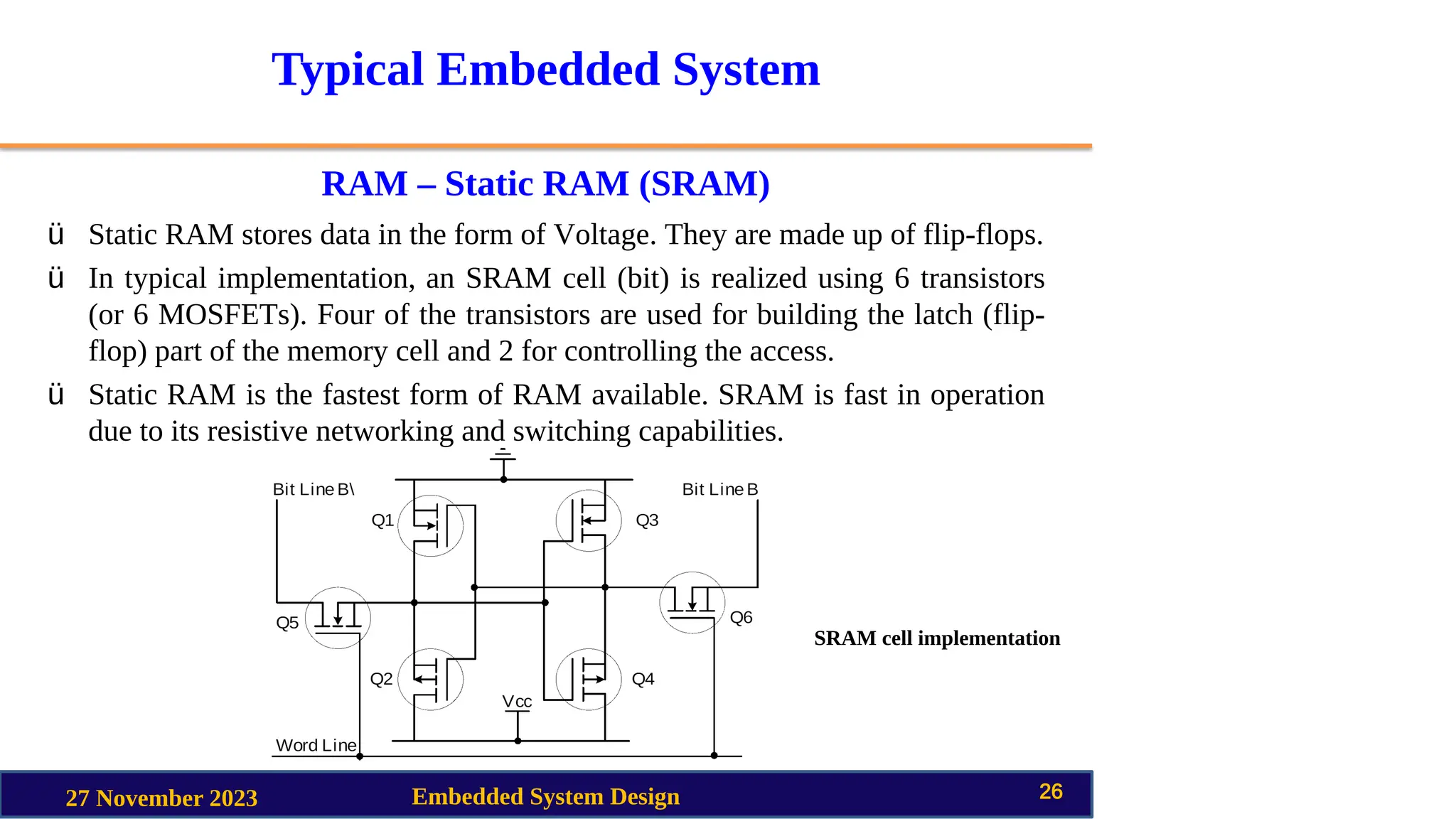
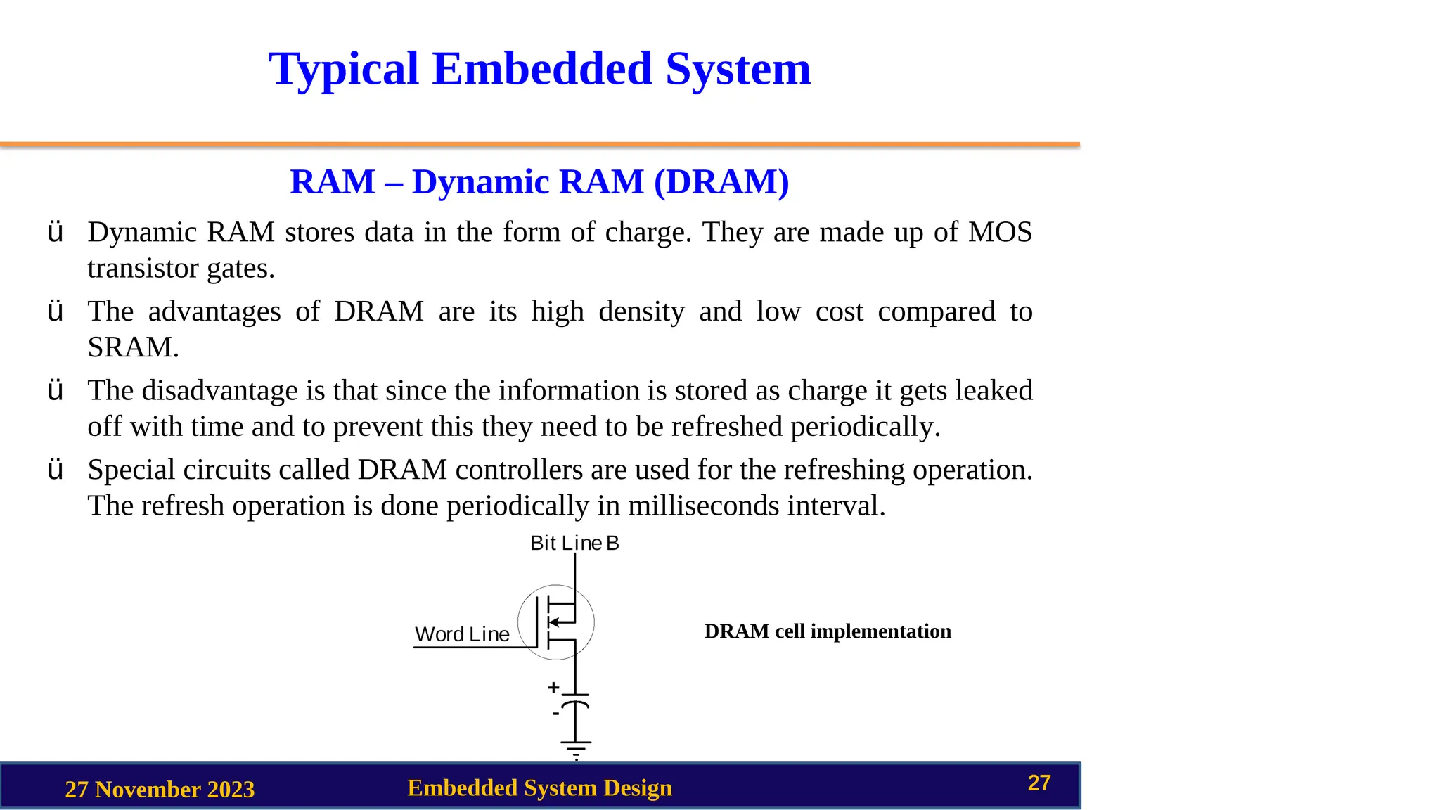
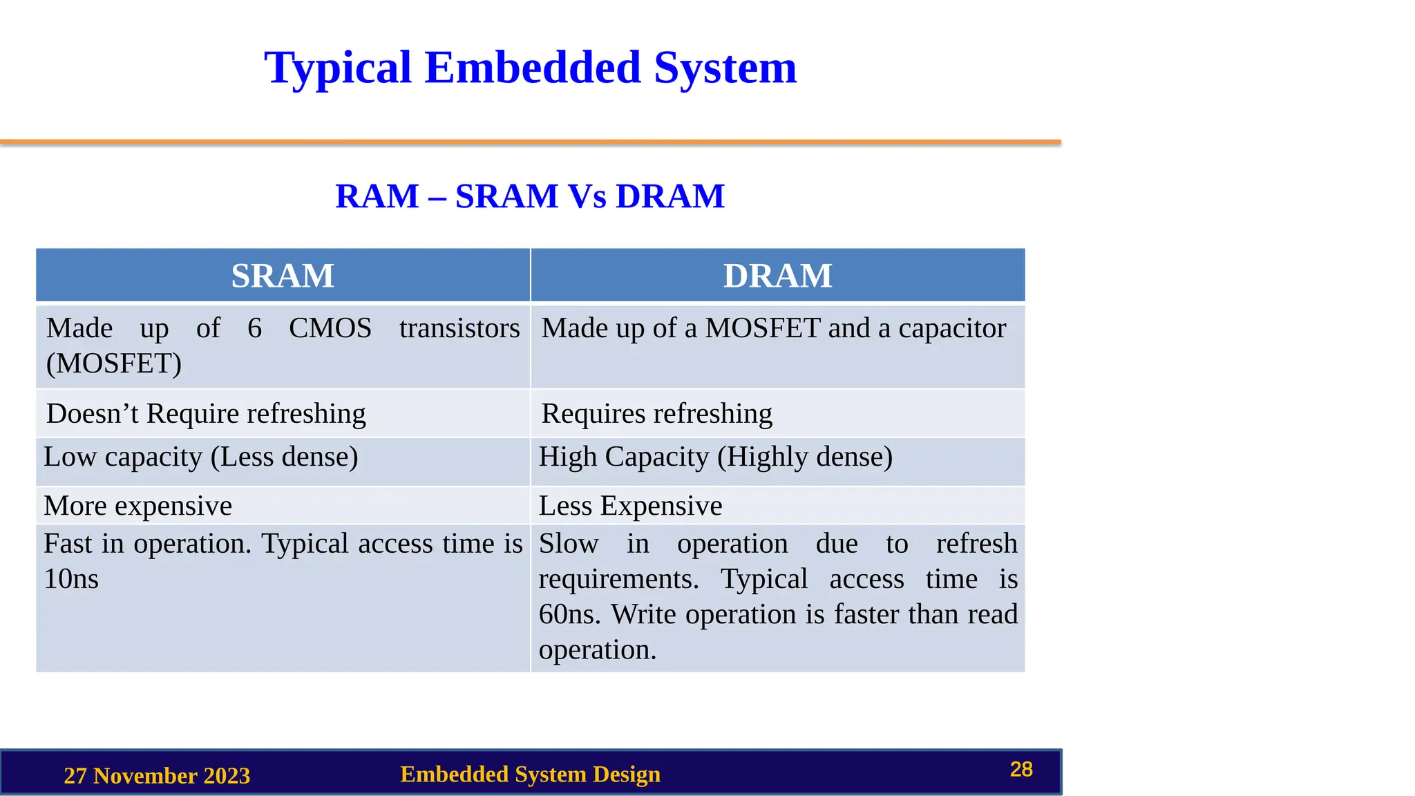
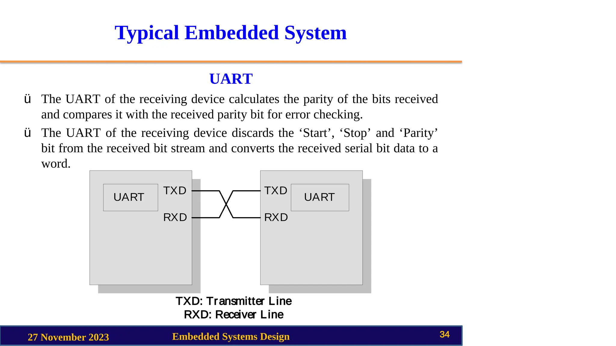
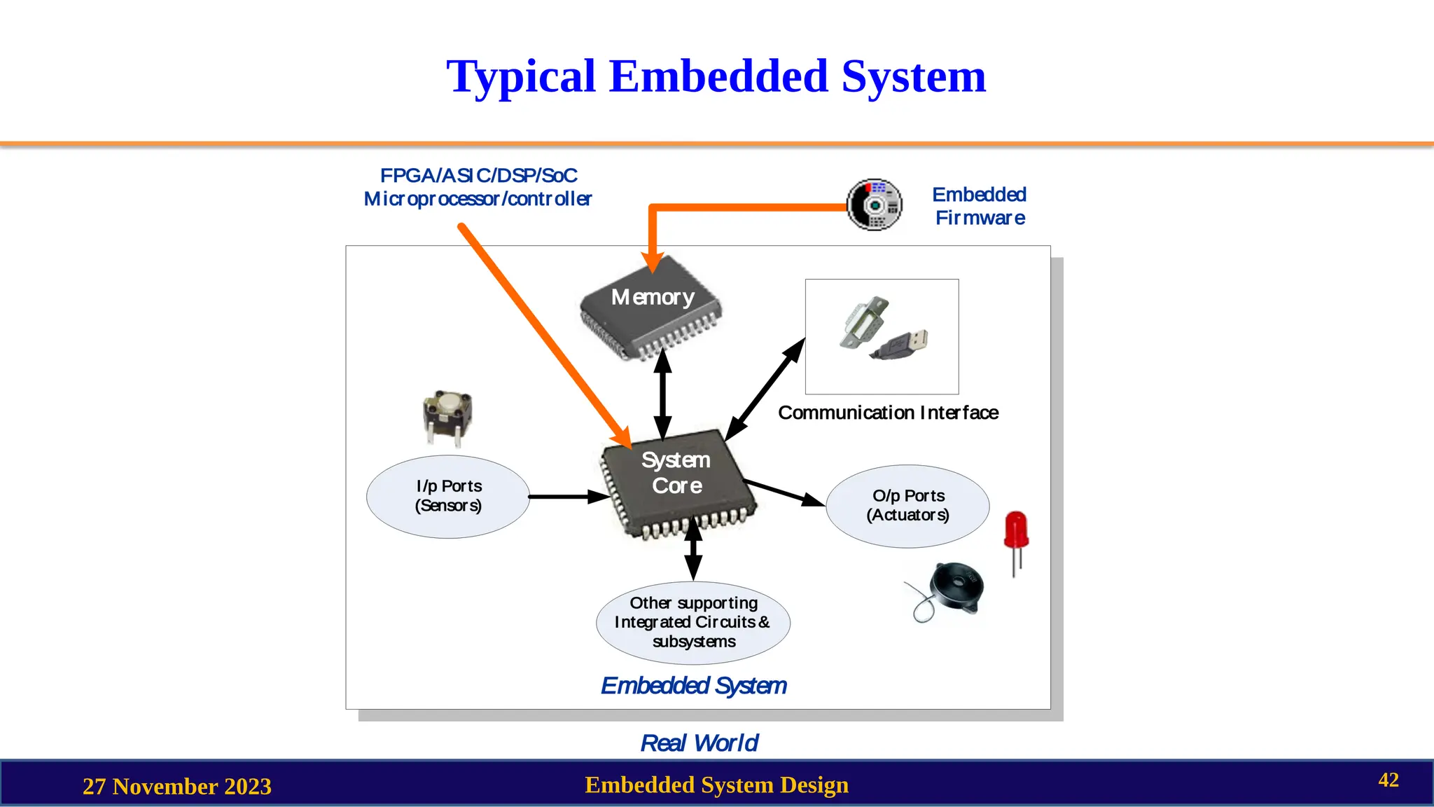
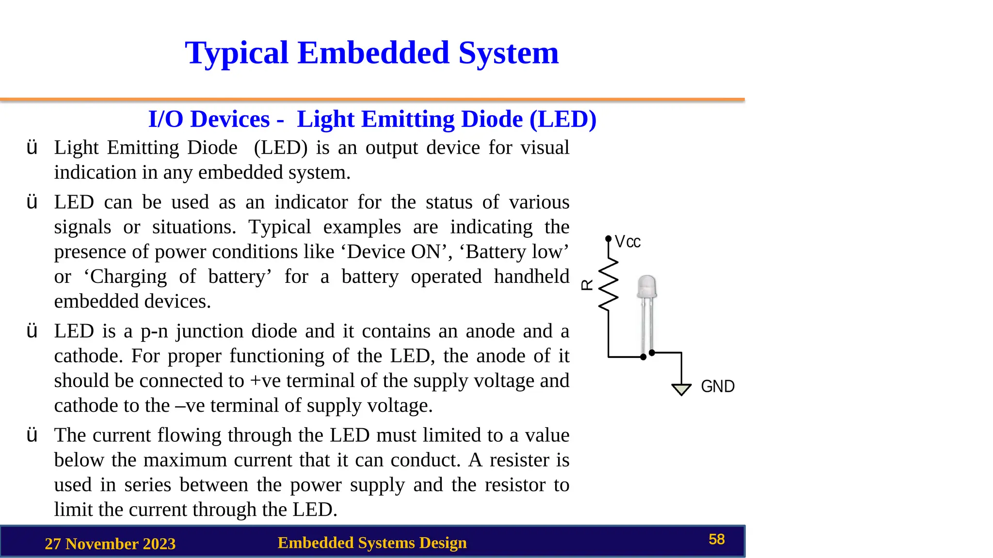
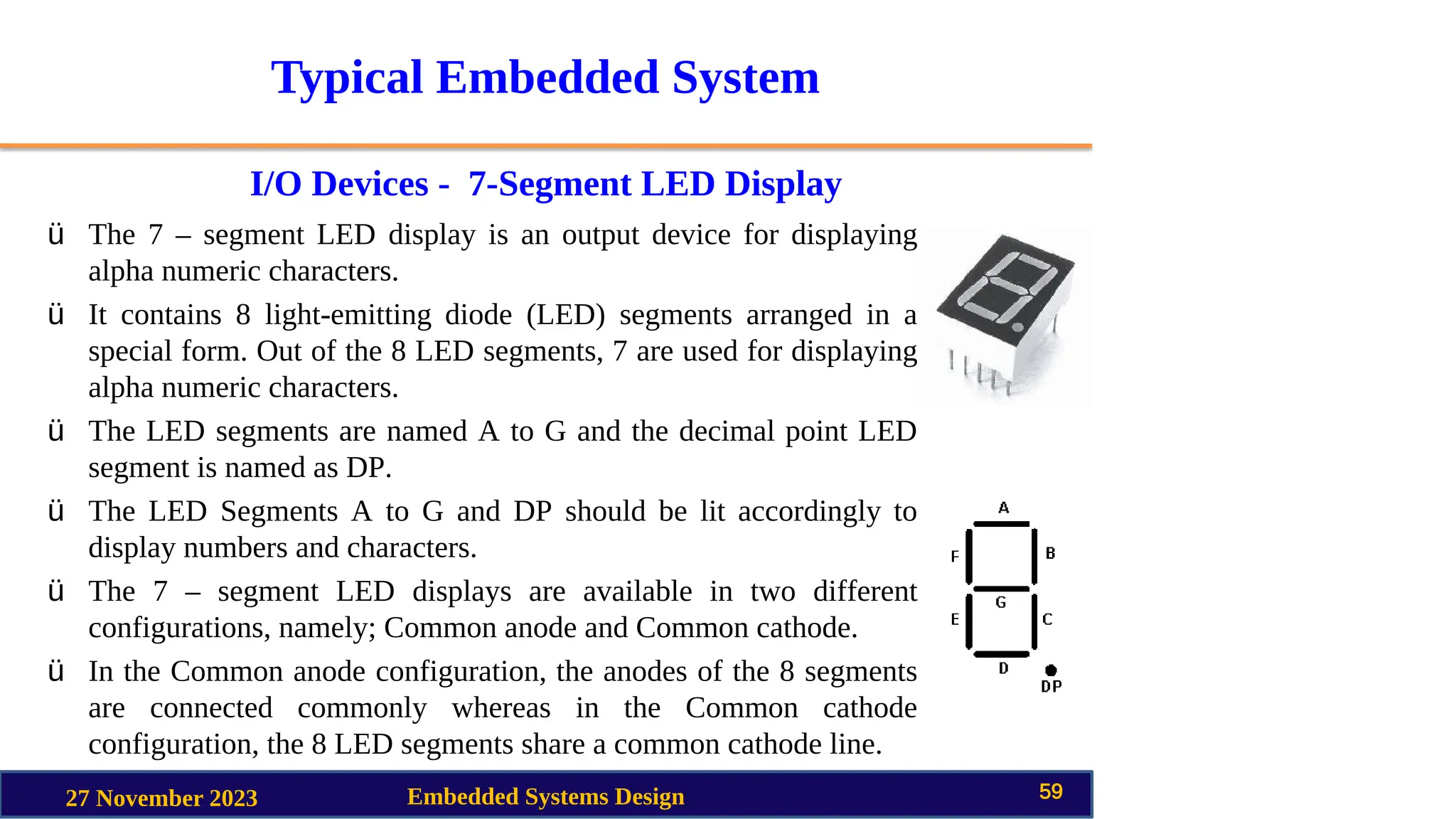
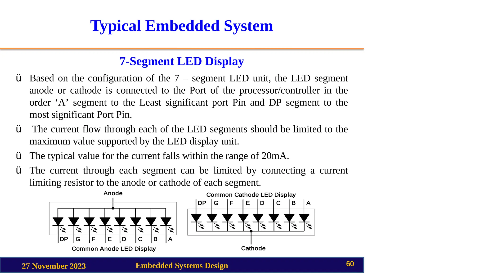
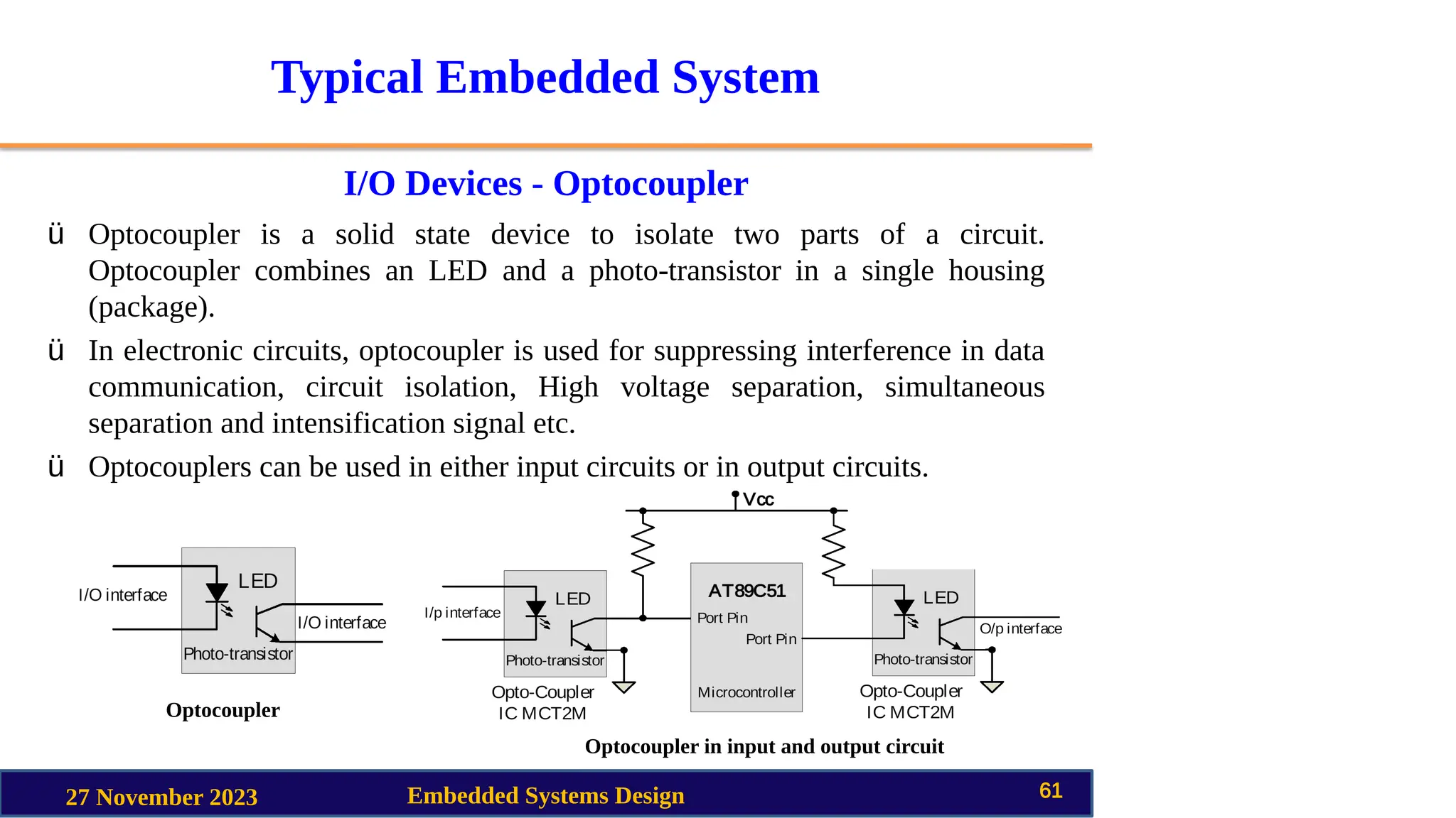
SlideShare a Scribd company logo
1 of 68
Download to read offline
Embedded System Design
Unit II
Typical Embedded System
Mr. A. Chandra Shaker
Asst. Professor
11/27/2023 Embedded System Design 1
Typical Embedded System
Unit II
• Core of Embedded System
• Memory
• Sensors and Actuators
• Communication Interface
11/27/2023 Embedded System Design 2
Typical Embedded System
11/27/2023 Embedded System Design 3
Typical Embedded System
Core of Embedded System
The core of the embedded system falls into any one of the following categories.
q General Purpose and Domain Specific Processors
q Microprocessors
q Microcontrollers
q Digital Signal Processors
q Programmable Logic Devices (PLDs)
q Application Specific Integrated Circuits (ASICs)
q Commercial Off-the-Shelf Components (COTS)
11/27/2023 Embedded System Design 4
Typical Embedded System
General Purpose Processor (GPP) Vs Application Specific
Instruction Set Processor (ASIP*)
11/27/2023 Embedded System Design 5
ü General Purpose Processor or GPP is a processor designed for general
computational tasks.
ü GPPs are produced in large volumes and targeting the general market. Due to
the high volume production, the per unit cost for a chip is low compared to
ASIC or other specific ICs.
ü A typical general purpose processor contains an Arithmetic and Logic Unit
(ALU) and Control Unit (CU).
ü Application Specific Instruction Set Processors (ASIPs) are processors with
architecture and instruction set optimized to specific domain/application
requirements like network processing, automotive, telecom, media applications,
digital signal processing, control applications etc.
* ASIP means Domain Specific Processor
Typical Embedded System
General Purpose Processor (GPP) Vs Application Specific
Instruction Set Processor (ASIP*)
11/27/2023 Embedded System Design 6
ü ASIPs fill the architectural spectrum between General Purpose Processors and
Application Specific Integrated Circuits (ASICs).
ü The need for an ASIP arises when the traditional general purpose processor are
unable to meet the increasing application needs.
ü Some Microcontrollers (like Automotive AVR, USB AVR from Atmel), System
on Chips, Digital Signal Processors, etc. are examples of Application Specific
Instruction Set Processors (ASIPs).
ü ASIPs incorporate a processor and on-chip peripherals, demanded by the
application requirement, program and data memory.
* ASIP means Domain Specific
Processor
Typical Embedded System
Microprocessors
11/27/2023 Embedded System Design 7
ü A silicon chip representing a Central Processing Unit (CPU), which is capable
of performing arithmetic as well as logical operations according to a pre-
defined set of Instructions, which is specific to the manufacturer.
ü In general the CPU contains the Arithmetic and Logic Unit (ALU), Control
Unit and Working registers.
ü Microprocessor is a dependant unit and it requires the combination of other
hardware like Memory, Timer Unit, and Interrupt Controller etc. for proper
functioning.
ü Intel claims the credit for developing the first Microprocessor unit, Intel 4004, a
4 bit processor which was released in Nov 1971.
Typical Embedded System
Microcontrollers
11/27/2023 Embedded System Design 8
ü A highly integrated silicon chip containing a CPU, scratch pad RAM, Special
and General purpose Register Arrays, On Chip ROM/FLASH memory for
program storage, Timer and Interrupt control units and dedicated I/O ports.
ü Microcontrollers can be considered as a super set of Microprocessors.
ü Microcontroller can be general purpose (like Intel 8051, designed for generic
applications and domains) or application specific (like Automotive AVR from
Atmel Corporation designed specifically for automotive applications).
ü Since a microcontroller contains all the necessary functional blocks for
independent working, they found greater place in the embedded domain in
place of microprocessors.
ü Microcontrollers are cheap, cost effective and are readily available in the
market.
ü Texas Instruments TMS 1000 is considered as the world’s first microcontroller.
Typical Embedded System
Microprocessors Vs Microcontrollers
11/27/2023 Embedded System Design 9
Microprocessors Microcontrollers
A silicon chip representing a Central Processing Unit
(CPU), which is capable of performing arithmetic as well
as logical operations according to a pre-defined set of
Instructions
A microcontroller is a highly integrated chip that contains
a CPU, scratch pad RAM, Special and General purpose
Register Arrays, On Chip ROM/FLASH memory for
program storage, Timer and Interrupt control units and
dedicated I/O ports
It is a dependent unit. It requires the combination of other
chips like Timers, Program and data memory chips,
Interrupt controllers etc for functioning
It is a self contained unit and it doesn’t require external
Interrupt Controller, Timer, UART etc for its functioning
Most of the time general purpose in design and operation Mostly application oriented or domain specific
Doesn’t contain a built in I/O port. The I/O Port
functionality needs to be implemented with the help of
external Programmable Peripheral Interface Chips like
8255
Most of the processors contain multiple built-in I/O ports
which can be operated as a single 8 or 16 or 32 bit Port or
as individual port pins
Targeted for high end market where performance is
important
Targeted for embedded market where performance is not
so critical (At present this demarcation is invalid)
Limited power saving options compared to
microcontrollers
Includes lot of power saving features
Typical Embedded System
Digital Signal Processors (DSPs)
11/27/2023 Embedded System Design 10
ü Powerful special purpose 8/16/32 bit microprocessors designed specifically to
meet the computational demands and power constraints of today's embedded
audio, video, and communications applications.
ü Digital Signal Processors are 2 to 3 times faster than the general purpose
microprocessors in signal processing applications.
ü DSPs implement algorithms in hardware which speeds up the execution
whereas general purpose processors implement the algorithm in firmware and
the speed of execution depends primarily on the clock for the processors.
ü DSP can be viewed as a microchip designed for performing high speed
computational operations for ‘addition’, ‘subtraction’, ‘multiplication’ and
‘division’.
Typical Embedded System
Digital Signal Processors (DSPs)
11/27/2023 Embedded System Design 11
ü A typical Digital Signal Processor incorporates the following key units:
ü Program Memory
ü Data Memory
ü Computational Engine
ü I/O Unit
ü Audio video signal processing, telecommunication and multimedia
applications are typical examples where DSP is employed.
Embedded System Design
(IV B.Tech I Sem ETE)
Faculty
Mr. A. Chandra Shaker
Asst. Professor
11/27/2023 Embedded System Design 12
Syllabus
11/27/2023 Embedded System Design 13
Syllabus
11/27/2023 Embedded System Design 14
Syllabus
11/27/2023 Embedded System Design 15
Embedded System Design
Unit II
Typical Embedded System
Mr. A. Chandra Shaker
Asst. Prof
27 November 2023 Embedded System Design 16
Typical Embedded System
Unit II
• Core of Embedded System
• Memory
• Sensors and Actuators
• Communication Interface
27 November 2023 Embedded System Design 17
Typical Embedded System
Memory
27 November 2023 Embedded System Design 18
ü Memory is an important part of an embedded system. The memory used in
embedded system can be either Program Storage Memory (ROM) or Data
memory (RAM).
ü Certain Embedded processors/controllers contain built in program memory
and data memory and this memory is known as on-chip memory.
Typical Embedded System
Memory – Program Storage Memory (ROM)
27 November 2023 Embedded System Design 19
ü Stores the program instructions.
ü Retains its contents even after the power to it is turned off. It is generally
known as Non volatile storage memory.
ü Depending on the fabrication, erasing and programming techniques they are
classified into:
Typical Embedded System
Program Storage Memory – Masked ROM (MROM)
27 November 2023 Embedded System Design 20
ü One-time programmable memory.
ü Uses hardwired technology for storing data.
ü The device is factory programmed by masking and metallization process
according to the data provided by the end user.
ü The primary advantage of MROM is low cost for high volume production.
They are the least expensive type of solid state memory.
ü The limitation with MROM based firmware storage is the inability to modify
the device firmware against firmware upgrades. Since the MROM is permanent
in bit storage, it is not possible to alter the bit information.
ü Different mechanisms are used for the masking process of the ROM.
Typical Embedded System
Program Storage Memory – Programmable Read Only Memory
(PROM) / (OTP)
27 November 2023 Embedded System Design 21
ü Unlike MROM it is not pre-programmed by the manufacturer.
ü PROM/OTP has nichrome or polysilicon wires arranged in a matrix, these
wires can be functionally viewed as fuses.
ü It is programmed by a PROM programmer which selectively burns the fuses
according to the bit pattern to be stored.
ü Fuses which are not blown/burned represents a logic “1” where as fuses which
are blown/burned represents a logic “0”.The default state is logic “1”.
ü OTP is widely used for commercial production of embedded systems whose
proto-typed versions are proven and the code is finalized.
ü It is a low cost solution for commercial production. OTPs cannot be
reprogrammed.
Typical Embedded System
Program Storage Memory – Erasable Programmable Read Only
Memory (EPROM)
27 November 2023 Embedded System Design 22
ü Erasable Programmable Read Only (EPROM) memory gives the flexibility to
re-program the same chip.
ü EPROM stores the bit information by charging the floating gate of an FET.
ü Bit information is stored by using an EPROM Programmer, which applies high
voltage to charge the floating gate.
ü EPROM contains a quartz crystal window for erasing the stored information. If
the window is exposed to Ultra violet rays for a fixed duration, the entire
memory will be erased.
ü Even though the EPROM chip is flexible in terms of re-programmability, it
needs to be taken out of the circuit board and needs to be put in a UV eraser
device for 20 to 30 minutes.
Typical Embedded System
Program Storage Memory – Electrically Erasable Programmable
Read Only Memory (EEPROM)
27 November 2023 Embedded System Design 23
ü Electrically Erasable Programmable Read Only (EEPROM) memory gives the
flexibility to re-program the same chip using electrical signals.
ü The information contained in the EEPROM memory can be altered by using
electrical signals at the register/byte level.
ü They can be erased and reprogrammed within the circuit.
ü These chips include a chip erase mode and in this mode they can be erased in a
few milliseconds.
ü It provides greater flexibility for system design.
ü The only limitation is their capacity is limited when compared with the
standard ROM (A few kilobytes).
Typical Embedded System
Program Storage Memory – FLASH
27 November 2023 Embedded System Design 24
ü FLASH memory is a variation of EEPROM technology.
ü It combines the re-programmability of EEPROM and the high capacity of
standard ROMs.
ü FLASH memory is organized as sectors (blocks) or pages.
ü FLASH memory stores information in an array of floating gate MOSFET
transistors.
ü The erasing of memory can be done at sector level or page level without
affecting the other sectors or pages.
ü Each sector/page should be erased before re-programming.
Typical Embedded System
Memory – Read-Write Memory/Random Access Memory
(RAM)
27 November 2023 Embedded System Design 25
ü RAM is the data memory or working memory of the controller/processor.
ü RAM is volatile, meaning when the power is turned off, all the contents are
destroyed.
ü RAM is a direct access memory, meaning we can access the desired memory
location directly without the need for traversing through the entire memory
locations to reach the desired memory position (i.e. Random Access of
memory location).
Typical Embedded System
RAM – Static RAM (SRAM)
27 November 2023 Embedded System Design 26
ü Static RAM stores data in the form of Voltage. They are made up of flip-flops.
ü In typical implementation, an SRAM cell (bit) is realized using 6 transistors
(or 6 MOSFETs). Four of the transistors are used for building the latch (flip-
flop) part of the memory cell and 2 for controlling the access.
ü Static RAM is the fastest form of RAM available. SRAM is fast in operation
due to its resistive networking and switching capabilities.
SRAM cell implementation
Typical Embedded System
RAM – Dynamic RAM (DRAM)
27 November 2023 Embedded System Design 27
ü Dynamic RAM stores data in the form of charge. They are made up of MOS
transistor gates.
ü The advantages of DRAM are its high density and low cost compared to
SRAM.
ü The disadvantage is that since the information is stored as charge it gets leaked
off with time and to prevent this they need to be refreshed periodically.
ü Special circuits called DRAM controllers are used for the refreshing operation.
The refresh operation is done periodically in milliseconds interval.
DRAM cell implementation
Typical Embedded System
RAM – SRAM Vs DRAM
27 November 2023 Embedded System Design 28
SRAM DRAM
Made up of 6 CMOS transistors
(MOSFET)
Made up of a MOSFET and a capacitor
Doesn’t Require refreshing Requires refreshing
Low capacity (Less dense) High Capacity (Highly dense)
More expensive Less Expensive
Fast in operation. Typical access time is
10ns
Slow in operation due to refresh
requirements. Typical access time is
60ns. Write operation is faster than read
operation.
Typical Embedded System
RAM – Non Volatile RAM (NVRAM)
27 November 2023 Embedded System Design 29
ü Random access memory with battery backup.
ü It contains Static RAM based memory and a minute battery for providing
supply to the memory in the absence of external power supply.
ü The memory and battery are packed together in a single package.
ü NVRAM is used for the non volatile storage of results of operations or for
setting up of flags etc.
ü The life span of NVRAM is expected to be around 10 years.
ü DS1744 from Maxim/Dallas is an example for 32KB NVRAM.
Embedded System Design
Unit II
Typical Embedded System
Mr. A. Chandra Shaker
Asst. Prof.
27 November 2023 Embedded System Design 30
Typical Embedded System
Unit II
• Core of Embedded System
• Memory
• Sensors and Actuators
• Communication Interface
27 November 2023 Embedded System Design 31
Typical Embedded System
On-board Communication Interface – UART
27 November 2023 Embedded Systems Design 32
ü Universal Asynchronous Receiver Transmitter (UART) based data
transmission is an asynchronous form of serial data transmission.
ü The serial communication settings (Baud rate, No. of bits per byte, parity,
No. of start bits and stop bit and flow control) for both transmitter and
receiver should be set as identical.
ü The start and stop of communication is indicated through inserting special
bits in the data stream.
Typical Embedded System
On-board Communication Interface – UART
27 November 2023 Embedded Systems Design 33
ü While sending a byte of data, a start bit is added first and a stop bit is added
at the end of the bit stream. The least significant bit of the data byte follows
the start bit.
ü The ‘Start’ bit informs the receiver that a data byte is about to arrive. The
receiver device starts polling its ‘receive line’ as per the baud rate settings.
ü If parity is enabled for communication, the UART of the transmitting device
adds a parity bit.
Typical Embedded System
UART
27 November 2023 Embedded Systems Design 34
ü The UART of the receiving device calculates the parity of the bits received
and compares it with the received parity bit for error checking.
ü The UART of the receiving device discards the ‘Start’, ‘Stop’ and ‘Parity’
bit from the received bit stream and converts the received serial bit data to a
word.
Embedded System Design
Unit II
Typical Embedded System
Mr. A. Chandra Shaker
Asst. Prof.
27 November 2023 Embedded System Design 35
Typical Embedded System
Unit II
• Core of Embedded System
• Memory
• Sensors and Actuators
• Communication Interface
27 November 2023 Embedded System Design 36
Typical Embedded System
On-board Communication Interface – UART
27 November 2023 Embedded Systems Design 37
ü Universal Asynchronous Receiver Transmitter (UART) based data
transmission is an asynchronous form of serial data transmission.
ü The serial communication settings (Baud rate, No. of bits per byte, parity,
No. of start bits and stop bit and flow control) for both transmitter and
receiver should be set as identical.
ü The start and stop of communication is indicated through inserting special
bits in the data stream.
Typical Embedded System
On-board Communication Interface – UART
27 November 2023 Embedded Systems Design 38
ü While sending a byte of data, a start bit is added first and a stop bit is added
at the end of the bit stream. The least significant bit of the data byte follows
the start bit.
ü The ‘Start’ bit informs the receiver that a data byte is about to arrive. The
receiver device starts polling its ‘receive line’ as per the baud rate settings.
ü If parity is enabled for communication, the UART of the transmitting device
adds a parity bit.
Typical Embedded System
UART
27 November 2023 Embedded Systems Design 39
ü The UART of the receiving device calculates the parity of the bits received
and compares it with the received parity bit for error checking.
ü The UART of the receiving device discards the ‘Start’, ‘Stop’ and ‘Parity’
bit from the received bit stream and converts the received serial bit data to a
word.
Embedded System Design
Unit II
Typical Embedded System
Mr. A. Chandra Shaker
Asst. Prof.
27 November 2023 Embedded System Design 40
Typical Embedded System
Unit II
• Core of Embedded System
• Memory
• Sensors and Actuators
• Communication Interface
27 November 2023 Embedded System Design 41
Typical Embedded System
27 November 2023 Embedded System Design 42
Typical Embedded System
Communication Interface
27 November 2023 Embedded Systems Design 43
ü Communication interface is essential for communicating with various
subsystems of the embedded system and with the external world.
ü For an embedded product, the communication interface can be viewed in two
different perspectives; namely; Device/board level communication interface
(Onboard Communication Interface) and Product level communication
interface (External Communication Interface).
ü Embedded product is a combination of different types of components
(chips/devices) arranged on a Printed Circuit Board (PCB).
ü The communication channel which interconnects the various components
within an embedded product is referred as Device/board level
communication interface (Onboard Communication Interface).
Typical Embedded System
Communication Interface
27 November 2023 Embedded Systems Design 44
ü Serial interfaces like I2C, SPI, UART, 1-Wire etc and Parallel bus interface
are examples of ‘Onboard Communication Interface’.
ü The ‘Product level communication interface’ (External Communication
Interface) is responsible for data transfer between the embedded system and
other devices or modules.
ü The external communication interface can be either wired media or wireless
media and it can be a serial or parallel interface. Infrared (IR), Bluetooth
(BT), Wireless LAN (Wi-Fi), Radio Frequency waves (RF), GPRS etc are
examples for wireless communication interface.
ü RS-232C/RS-422/RS 485, USB, Ethernet (TCP-IP), IEEE 1394 port, Parallel
port, CF-II Slot, SDIO, PCMCIA etc are examples for wired interfaces.
Typical Embedded System
On-board Communication Interface – I2C
27 November 2023 Embedded Systems Design 45
ü Inter Integrated Circuit Bus (I2C - Pronounced ‘I square C’) is a
synchronous bi-directional half duplex (one-directional communication at a
given point of time) two wire serial interface bus.
ü The concept of I2C bus was developed by ‘Philips Semiconductors’ in the
early 1980’s. The original intention of I2C was to provide an easy way of
connection between a microprocessor/microcontroller system and the
peripheral chips in Television sets.
ü The I2C bus is comprised of two bus lines, namely; Serial Clock – SCL and
Serial Data – SDA.
ü SCL line is responsible for generating synchronization clock pulses and SDA
is responsible for transmitting the serial data across devices.
Typical Embedded System
I2C
27 November 2023 Embedded Systems Design 46
ü I2C bus is a shared bus system to which many number of I2C devices can be
connected. Devices connected to the I2C bus can act as either ‘Master’
device or ‘Slave’ device.
ü The ‘Master’ device is responsible for controlling the communication by
initiating/terminating data transfer, sending data and generating necessary
synchronization clock pulses.
ü ‘Slave’ devices wait for the commands from the master and respond upon
receiving the commands.
ü ‘Master’ and ‘Slave’ devices can act as either transmitter or receiver.
ü Regardless whether a master is acting as transmitter or receiver, the
synchronization clock signal is generated by the ‘Master’ device only.
ü I2C supports multi masters on the same bus.
Typical Embedded System
I2C
27 November 2023 Embedded Systems Design 47
Typical Embedded System
I2C
27 November 2023 Embedded Systems Design 48
ü The sequence of operation for communicating with an I2C slave device is:
1. Master device pulls the clock line (SCL) of the bus to ‘HIGH’.
2. Master device pulls the data line (SDA) ‘LOW’, when the SCL line is
at logic ‘HIGH’ (This is the ‘Start’ condition for data transfer).
3. Master sends the address (7 bit or 10 bit wide) of the ‘Slave’ device to
which it wants to communicate, over the SDA line. Clock pulses are
generated at the SCL line for synchronizing the bit reception by the
slave device. The MSB of the data is always transmitted first. The data
in the bus is valid during the ‘HIGH’ period of the clock signal.
4. Master sends the Read or Write bit (Bit value = 1 Read Operation; Bit
value = 0 Write Operation) according to the requirement.
5. Master waits for the acknowledgement bit from the slave device whose
address is sent on the bus along with the Read/Write operation
command. Slave devices connected to the bus compares the address
received with the address assigned to them.
Typical Embedded System
I2C
27 November 2023 Embedded Systems Design 49
6. The Slave device with the address requested by the master device
responds by sending an acknowledge bit (Bit value =1) over the SDA
line.
7. Upon receiving the acknowledge bit, master sends the 8bit data to the
slave device over SDA line, if the requested operation is ‘Write to
device’. If the requested operation is ‘Read from device’, the slave
device sends data to the master over the SDA line.
8. Master waits for the acknowledgement bit from the device upon byte
transfer complete for a write operation and sends an acknowledge bit to
the slave device for a read operation.
9. Master terminates the transfer by pulling the SDA line ‘HIGH’ when
the clock line SCL is at logic ‘HIGH’ (Indicating the ‘STOP’
condition).
Typical Embedded System
On-board Communication Interface – SPI
27 November 2023 Embedded Systems Design 50
ü The Serial Peripheral Interface Bus (SPI) is a synchronous bi-directional full
duplex four wire serial interface bus.
ü The concept of SPI is introduced by Motorola.
ü SPI is a single master multi-slave system. It is possible to have a system
where more than one SPI device can be master, provided the condition only
one master device is active at any given point of time, is satisfied.
ü SPI requires four signal lines for communication. They are:
q Master Out Slave In (MOSI): Signal line carrying the data from master to
slave device. It is also known as Slave Input/Slave Data In (SI/SDI).
q Master In Slave Out (MISO): Signal line carrying the data from slave to
master device. It is also known as Slave Output (SO/SDO).
q Serial Clock (SCLK): Signal line carrying the clock signals.
q Slave Select (SS): Signal line for slave device select. It is an active low signal.
Typical Embedded System
SPI
27 November 2023 Embedded Systems Design 51
Typical Embedded System
SPI
27 November 2023 Embedded Systems Design 52
ü The master device is responsible for generating the clock signal.
ü Master device selects the required slave device by asserting the
corresponding slave device’s slave select signal ‘LOW’.
ü The data out line (MISO) of all the slave devices when not selected floats at
high impedance state.
ü The serial data transmission through SPI Bus is fully configurable. SPI
devices contain certain set of registers for holding these configurations.
ü The Serial Peripheral Control Register holds the various configuration
parameters like master/slave selection for the device, baud rate selection for
communication, clock signal control etc.
ü The status register holds the status of various conditions for transmission and
reception.
Typical Embedded System
SPI
27 November 2023 Embedded Systems Design 53
ü SPI works on the principle of ‘Shift Register’.
ü The master and slave devices contain a special shift register for the data to
transmit or receive.
ü The size of the shift register is device dependent. Normally it is a multiple of
8.
ü During transmission from the master to slave, the data in the master’s shift
register is shifted out to the MOSI pin and it enters the shift register of the
slave device through the MOSI pin of the slave device.
ü At the same time the shifted out data bit from the slave device’s shift register
enters the shift register of the master device through MISO pin.
Embedded System Design
Unit II
Typical Embedded System
Mr. A. Chandra Shaker
Asst.Prof
27 November 2023 Embedded System Design 54
Typical Embedded System
Unit II
• Core of Embedded System
• Memory
• Sensors and Actuators
• Communication Interface
27 November 2023 Embedded System Design 55
Typical Embedded System
Sensors and Actuators
27 November 2023 Embedded Systems Design 56
Sensor:
A transducer device which converts energy from one form to another for any
measurement or control purpose. Sensors acts as input device.
Eg. Hall Effect sensor which measures the distance between the cushion and
magnet in the Smart Running shoes from Adidas.
Actuator:
A form of transducer device (mechanical or electrical) which converts signals to
corresponding physical action (motion). Actuator acts as an output device.
Eg. Micro motor actuator which adjusts the position of the cushioning element in
the Smart Running shoes from Adidas.
Typical Embedded System
The I/O Subsystem
27 November 2023 Embedded Systems Design 57
ü The I/O subsystem of the embedded system facilitates the interaction of the
embedded system with external world.
ü The interaction happens through the sensors and actuators connected to the
Input and output ports respectively of the embedded system.
ü The sensors may not be directly interfaced to the Input ports, instead they may
be interfaced through signal conditioning and translating systems like ADC,
Optocouplers etc.
Typical Embedded System
I/O Devices - Light Emitting Diode (LED)
27 November 2023 Embedded Systems Design 58
ü Light Emitting Diode (LED) is an output device for visual
indication in any embedded system.
ü LED can be used as an indicator for the status of various
signals or situations. Typical examples are indicating the
presence of power conditions like ‘Device ON’, ‘Battery low’
or ‘Charging of battery’ for a battery operated handheld
embedded devices.
ü LED is a p-n junction diode and it contains an anode and a
cathode. For proper functioning of the LED, the anode of it
should be connected to +ve terminal of the supply voltage and
cathode to the –ve terminal of supply voltage.
ü The current flowing through the LED must limited to a value
below the maximum current that it can conduct. A resister is
used in series between the power supply and the resistor to
limit the current through the LED.
Typical Embedded System
I/O Devices - 7-Segment LED Display
27 November 2023 Embedded Systems Design 59
ü The 7 – segment LED display is an output device for displaying
alpha numeric characters.
ü It contains 8 light-emitting diode (LED) segments arranged in a
special form. Out of the 8 LED segments, 7 are used for displaying
alpha numeric characters.
ü The LED segments are named A to G and the decimal point LED
segment is named as DP.
ü The LED Segments A to G and DP should be lit accordingly to
display numbers and characters.
ü The 7 – segment LED displays are available in two different
configurations, namely; Common anode and Common cathode.
ü In the Common anode configuration, the anodes of the 8 segments
are connected commonly whereas in the Common cathode
configuration, the 8 LED segments share a common cathode line.
Typical Embedded System
7-Segment LED Display
27 November 2023 Embedded Systems Design 60
ü Based on the configuration of the 7 – segment LED unit, the LED segment
anode or cathode is connected to the Port of the processor/controller in the
order ‘A’ segment to the Least significant port Pin and DP segment to the
most significant Port Pin.
ü The current flow through each of the LED segments should be limited to the
maximum value supported by the LED display unit.
ü The typical value for the current falls within the range of 20mA.
ü The current through each segment can be limited by connecting a current
limiting resistor to the anode or cathode of each segment.
Typical Embedded System
I/O Devices - Optocoupler
27 November 2023 Embedded Systems Design 61
ü Optocoupler is a solid state device to isolate two parts of a circuit.
Optocoupler combines an LED and a photo-transistor in a single housing
(package).
ü In electronic circuits, optocoupler is used for suppressing interference in data
communication, circuit isolation, High voltage separation, simultaneous
separation and intensification signal etc.
ü Optocouplers can be used in either input circuits or in output circuits.
Optocoupler
Optocoupler in input and output circuit
Typical Embedded System
I/O Devices – Stepper Motor
27 November 2023 Embedded Systems Design 62
ü Stepper motor is an electro mechanical device which generates discrete
displacement (motion) in response to dc electrical signals.
ü It differs from the normal dc motor in its operation. The dc motor produces
continuous rotation on applying dc voltage whereas a stepper motor produces
discrete rotation in response to the dc voltage applied to it.
ü Stepper motors are widely used in industrial embedded applications, consumer
electronic products and robotics control systems.
ü The paper feed mechanism of a printer/fax makes use of stepper motors for its
functioning.
ü Based on the coil winding arrangements, a two phase stepper motor is
classified into:
q Unipolar
q Bipolar
Typical Embedded System
Stepper Motor
27 November 2023 Embedded Systems Design 63
ü Unipolar: A unipolar stepper motor contains two windings
per phase. The direction of rotation (clockwise or
anticlockwise) of a stepper motor is controlled by changing
the direction of current flow. Current in one direction flows
through one coil and in the opposite direction flows through
the other coil. It is easy to shift the direction of rotation by
just switching the terminals to which the coils are connected.
ü Bipolar: A bipolar stepper motor contains single winding
per phase. For reversing the motor rotation the current flow
through the windings is reversed dynamically. It requires
complex circuitry for current flow reversal.
Typical Embedded System
2 Phase Unipolar Stepper Motor – Stator Winding
27 November 2023 Embedded Systems Design 64
Typical Embedded System
2 Phase Unipolar Stepper Motor – Stepping Sequence
27 November 2023 Embedded Systems Design 65
Full Step:
In the full step mode both the phases are energized simultaneously. The coils
A, B, C and D are energized in the order.
Step Coil A Coil B Coil C Coil D
1 H H L L
2 L H H L
3 L L H H
4 H L L H
Only one winding of a phase is energized at a time.
Typical Embedded System
2 Phase Unipolar Stepper Motor – Stepping Sequence
27 November 2023 Embedded Systems Design 66
Wave Step:
Only one phase is energized at a time and each coils of the phase are energized
alternatively. The coils A, B, C and D are energized in the order.
Step Coil A Coil B Coil C Coil D
1 H L L L
2 L H L L
3 L L H L
4 L L L H
Only one winding of a phase is energized at a time.
Typical Embedded System
2 Phase Unipolar Stepper Motor – Stepping Sequence
27 November 2023 Embedded Systems Design 67
Half Step:
Half step uses the combination of wave and full step. It has the highest torque
and stability. The coils A, B, C and D are energized in the order.
Step Coil A Coil B Coil C Coil D
1 H L L L
2 H H L L
3 L H L L
4 L H H L
5 L L H L
6 L L H H
7 L L L H
8 H L L H
The rotation of the stepper motor can be reversed by reversing the order in which
the coil is energized.
Typical Embedded System
2 Phase Unipolar Stepper Motor – Interfacing
27 November 2023 Embedded Systems Design 68
ü Depending on the current and voltage requirements, special driving circuits
are required to interface the stepper motor with microcontroller/processors.
ü Stepper motor driving ICs like ULN2803 or simple transistor based driving
circuit can be used for interfacing stepper motors with processor/controller.

More Related Content

Similar to Embedded system book very helpful needed and use by everyone

typicales-210510062115.pdf
typicales-210510062115.pdftypicales-210510062115.pdf
typicales-210510062115.pdfssuser136534
 
BRACU_SPRING24_EEE373_L1_Introduction.pptx
BRACU_SPRING24_EEE373_L1_Introduction.pptxBRACU_SPRING24_EEE373_L1_Introduction.pptx
BRACU_SPRING24_EEE373_L1_Introduction.pptxSKTAHMEDSALIMRAFID
 
18CS44-MODULE1-PPT.pptx
18CS44-MODULE1-PPT.pptx18CS44-MODULE1-PPT.pptx
18CS44-MODULE1-PPT.pptxKokilaK25
 
I. Introduction to Microprocessor System.ppt
I. Introduction to Microprocessor System.pptI. Introduction to Microprocessor System.ppt
I. Introduction to Microprocessor System.pptHAriesOa1
 
Embedded systems-unit-1
Embedded systems-unit-1Embedded systems-unit-1
Embedded systems-unit-1Prabhu Mali
 
8051 microcontroller
8051 microcontroller8051 microcontroller
8051 microcontrollersnehapvs
 
Embedded systems introduction
Embedded systems introductionEmbedded systems introduction
Embedded systems introductionmohamed drahem
 
International Journal of Computational Engineering Research(IJCER)
International Journal of Computational Engineering Research(IJCER)International Journal of Computational Engineering Research(IJCER)
International Journal of Computational Engineering Research(IJCER)ijceronline
 
EE6602 Embedded System
EE6602 Embedded SystemEE6602 Embedded System
EE6602 Embedded Systemrmkceteee
 
Embedded systems الانظمة المدمجة
Embedded systems  الانظمة المدمجة Embedded systems  الانظمة المدمجة
Embedded systems الانظمة المدمجة salih mahmod
 
Ppt on embedded system
Ppt on embedded systemPpt on embedded system
Ppt on embedded systemPankaj joshi
 
MTE104-L2: Overview of Microcontrollers
MTE104-L2: Overview of MicrocontrollersMTE104-L2: Overview of Microcontrollers
MTE104-L2: Overview of MicrocontrollersAbdalla Ahmed
 
Microcontroller presentation
Microcontroller presentationMicrocontroller presentation
Microcontroller presentationxavierpaulino
 
20838382 microprocessor-8085-notes
20838382 microprocessor-8085-notes20838382 microprocessor-8085-notes
20838382 microprocessor-8085-notesRavali Sunki
 
Ajal mod 1
Ajal mod 1Ajal mod 1
Ajal mod 1AJAL A J
 

Similar to Embedded system book very helpful needed and use by everyone (20)

typicales-210510062115.pdf
typicales-210510062115.pdftypicales-210510062115.pdf
typicales-210510062115.pdf
 
BRACU_SPRING24_EEE373_L1_Introduction.pptx
BRACU_SPRING24_EEE373_L1_Introduction.pptxBRACU_SPRING24_EEE373_L1_Introduction.pptx
BRACU_SPRING24_EEE373_L1_Introduction.pptx
 
18CS44-MODULE1-PPT.pptx
18CS44-MODULE1-PPT.pptx18CS44-MODULE1-PPT.pptx
18CS44-MODULE1-PPT.pptx
 
I. Introduction to Microprocessor System.ppt
I. Introduction to Microprocessor System.pptI. Introduction to Microprocessor System.ppt
I. Introduction to Microprocessor System.ppt
 
Embedded systems-unit-1
Embedded systems-unit-1Embedded systems-unit-1
Embedded systems-unit-1
 
M&i(lec#01)
M&i(lec#01)M&i(lec#01)
M&i(lec#01)
 
8051 microcontroller
8051 microcontroller8051 microcontroller
8051 microcontroller
 
Embedded systems introduction
Embedded systems introductionEmbedded systems introduction
Embedded systems introduction
 
International Journal of Computational Engineering Research(IJCER)
International Journal of Computational Engineering Research(IJCER)International Journal of Computational Engineering Research(IJCER)
International Journal of Computational Engineering Research(IJCER)
 
EE6602 Embedded System
EE6602 Embedded SystemEE6602 Embedded System
EE6602 Embedded System
 
Introduction to Embedded Systems
Introduction to Embedded SystemsIntroduction to Embedded Systems
Introduction to Embedded Systems
 
Embedded systems الانظمة المدمجة
Embedded systems  الانظمة المدمجة Embedded systems  الانظمة المدمجة
Embedded systems الانظمة المدمجة
 
ARM-Unit-1.pdf
ARM-Unit-1.pdfARM-Unit-1.pdf
ARM-Unit-1.pdf
 
Ppt on embedded system
Ppt on embedded systemPpt on embedded system
Ppt on embedded system
 
MTE104-L2: Overview of Microcontrollers
MTE104-L2: Overview of MicrocontrollersMTE104-L2: Overview of Microcontrollers
MTE104-L2: Overview of Microcontrollers
 
Microcontroller presentation
Microcontroller presentationMicrocontroller presentation
Microcontroller presentation
 
Day1
Day1Day1
Day1
 
Module-1 Embedded computing.pdf
Module-1 Embedded computing.pdfModule-1 Embedded computing.pdf
Module-1 Embedded computing.pdf
 
20838382 microprocessor-8085-notes
20838382 microprocessor-8085-notes20838382 microprocessor-8085-notes
20838382 microprocessor-8085-notes
 
Ajal mod 1
Ajal mod 1Ajal mod 1
Ajal mod 1
 

Recently uploaded

Internship report on mechanical engineering
Internship report on mechanical engineeringInternship report on mechanical engineering
Internship report on mechanical engineeringmalavadedarshan25
 
Introduction to Microprocesso programming and interfacing.pptx
Introduction to Microprocesso programming and interfacing.pptxIntroduction to Microprocesso programming and interfacing.pptx
Introduction to Microprocesso programming and interfacing.pptxvipinkmenon1
 
Study on Air-Water & Water-Water Heat Exchange in a Finned Tube Exchanger
Study on Air-Water & Water-Water Heat Exchange in a Finned Tube ExchangerStudy on Air-Water & Water-Water Heat Exchange in a Finned Tube Exchanger
Study on Air-Water & Water-Water Heat Exchange in a Finned Tube ExchangerAnamika Sarkar
 
chaitra-1.pptx fake news detection using machine learning
chaitra-1.pptx  fake news detection using machine learningchaitra-1.pptx  fake news detection using machine learning
chaitra-1.pptx fake news detection using machine learningmisbanausheenparvam
 
SPICE PARK APR2024 ( 6,793 SPICE Models )
SPICE PARK APR2024 ( 6,793 SPICE Models )SPICE PARK APR2024 ( 6,793 SPICE Models )
SPICE PARK APR2024 ( 6,793 SPICE Models )Tsuyoshi Horigome
 
CCS355 Neural Network & Deep Learning Unit II Notes with Question bank .pdf
CCS355 Neural Network & Deep Learning Unit II Notes with Question bank .pdfCCS355 Neural Network & Deep Learning Unit II Notes with Question bank .pdf
CCS355 Neural Network & Deep Learning Unit II Notes with Question bank .pdfAsst.prof M.Gokilavani
 
CCS355 Neural Network & Deep Learning UNIT III notes and Question bank .pdf
CCS355 Neural Network & Deep Learning UNIT III notes and Question bank .pdfCCS355 Neural Network & Deep Learning UNIT III notes and Question bank .pdf
CCS355 Neural Network & Deep Learning UNIT III notes and Question bank .pdfAsst.prof M.Gokilavani
 
Decoding Kotlin - Your guide to solving the mysterious in Kotlin.pptx
Decoding Kotlin - Your guide to solving the mysterious in Kotlin.pptxDecoding Kotlin - Your guide to solving the mysterious in Kotlin.pptx
Decoding Kotlin - Your guide to solving the mysterious in Kotlin.pptxJoão Esperancinha
 
VICTOR MAESTRE RAMIREZ - Planetary Defender on NASA's Double Asteroid Redirec...
VICTOR MAESTRE RAMIREZ - Planetary Defender on NASA's Double Asteroid Redirec...VICTOR MAESTRE RAMIREZ - Planetary Defender on NASA's Double Asteroid Redirec...
VICTOR MAESTRE RAMIREZ - Planetary Defender on NASA's Double Asteroid Redirec...VICTOR MAESTRE RAMIREZ
 
HARMONY IN THE HUMAN BEING - Unit-II UHV-2
HARMONY IN THE HUMAN BEING - Unit-II UHV-2HARMONY IN THE HUMAN BEING - Unit-II UHV-2
HARMONY IN THE HUMAN BEING - Unit-II UHV-2RajaP95
 
INFLUENCE OF NANOSILICA ON THE PROPERTIES OF CONCRETE
INFLUENCE OF NANOSILICA ON THE PROPERTIES OF CONCRETEINFLUENCE OF NANOSILICA ON THE PROPERTIES OF CONCRETE
INFLUENCE OF NANOSILICA ON THE PROPERTIES OF CONCRETEroselinkalist12
 
Call Girls Narol 7397865700 Independent Call Girls
Call Girls Narol 7397865700 Independent Call GirlsCall Girls Narol 7397865700 Independent Call Girls
Call Girls Narol 7397865700 Independent Call Girlsssuser7cb4ff
 
complete construction, environmental and economics information of biomass com...
complete construction, environmental and economics information of biomass com...complete construction, environmental and economics information of biomass com...
complete construction, environmental and economics information of biomass com...asadnawaz62
 
GDSC ASEB Gen AI study jams presentation
GDSC ASEB Gen AI study jams presentationGDSC ASEB Gen AI study jams presentation
GDSC ASEB Gen AI study jams presentationGDSCAESB
 
Introduction-To-Agricultural-Surveillance-Rover.pptx
Introduction-To-Agricultural-Surveillance-Rover.pptxIntroduction-To-Agricultural-Surveillance-Rover.pptx
Introduction-To-Agricultural-Surveillance-Rover.pptxk795866
 
Concrete Mix Design - IS 10262-2019 - .pptx
Concrete Mix Design - IS 10262-2019 - .pptxConcrete Mix Design - IS 10262-2019 - .pptx
Concrete Mix Design - IS 10262-2019 - .pptxKartikeyaDwivedi3
 
Oxy acetylene welding presentation note.
Oxy acetylene welding presentation note.Oxy acetylene welding presentation note.
Oxy acetylene welding presentation note.eptoze12
 
IVE Industry Focused Event - Defence Sector 2024
IVE Industry Focused Event - Defence Sector 2024IVE Industry Focused Event - Defence Sector 2024
IVE Industry Focused Event - Defence Sector 2024Mark Billinghurst
 

Recently uploaded (20)

Internship report on mechanical engineering
Internship report on mechanical engineeringInternship report on mechanical engineering
Internship report on mechanical engineering
 
Introduction to Microprocesso programming and interfacing.pptx
Introduction to Microprocesso programming and interfacing.pptxIntroduction to Microprocesso programming and interfacing.pptx
Introduction to Microprocesso programming and interfacing.pptx
 
Study on Air-Water & Water-Water Heat Exchange in a Finned Tube Exchanger
Study on Air-Water & Water-Water Heat Exchange in a Finned Tube ExchangerStudy on Air-Water & Water-Water Heat Exchange in a Finned Tube Exchanger
Study on Air-Water & Water-Water Heat Exchange in a Finned Tube Exchanger
 
chaitra-1.pptx fake news detection using machine learning
chaitra-1.pptx  fake news detection using machine learningchaitra-1.pptx  fake news detection using machine learning
chaitra-1.pptx fake news detection using machine learning
 
young call girls in Green Park🔝 9953056974 🔝 escort Service
young call girls in Green Park🔝 9953056974 🔝 escort Serviceyoung call girls in Green Park🔝 9953056974 🔝 escort Service
young call girls in Green Park🔝 9953056974 🔝 escort Service
 
SPICE PARK APR2024 ( 6,793 SPICE Models )
SPICE PARK APR2024 ( 6,793 SPICE Models )SPICE PARK APR2024 ( 6,793 SPICE Models )
SPICE PARK APR2024 ( 6,793 SPICE Models )
 
CCS355 Neural Network & Deep Learning Unit II Notes with Question bank .pdf
CCS355 Neural Network & Deep Learning Unit II Notes with Question bank .pdfCCS355 Neural Network & Deep Learning Unit II Notes with Question bank .pdf
CCS355 Neural Network & Deep Learning Unit II Notes with Question bank .pdf
 
CCS355 Neural Network & Deep Learning UNIT III notes and Question bank .pdf
CCS355 Neural Network & Deep Learning UNIT III notes and Question bank .pdfCCS355 Neural Network & Deep Learning UNIT III notes and Question bank .pdf
CCS355 Neural Network & Deep Learning UNIT III notes and Question bank .pdf
 
Decoding Kotlin - Your guide to solving the mysterious in Kotlin.pptx
Decoding Kotlin - Your guide to solving the mysterious in Kotlin.pptxDecoding Kotlin - Your guide to solving the mysterious in Kotlin.pptx
Decoding Kotlin - Your guide to solving the mysterious in Kotlin.pptx
 
VICTOR MAESTRE RAMIREZ - Planetary Defender on NASA's Double Asteroid Redirec...
VICTOR MAESTRE RAMIREZ - Planetary Defender on NASA's Double Asteroid Redirec...VICTOR MAESTRE RAMIREZ - Planetary Defender on NASA's Double Asteroid Redirec...
VICTOR MAESTRE RAMIREZ - Planetary Defender on NASA's Double Asteroid Redirec...
 
HARMONY IN THE HUMAN BEING - Unit-II UHV-2
HARMONY IN THE HUMAN BEING - Unit-II UHV-2HARMONY IN THE HUMAN BEING - Unit-II UHV-2
HARMONY IN THE HUMAN BEING - Unit-II UHV-2
 
INFLUENCE OF NANOSILICA ON THE PROPERTIES OF CONCRETE
INFLUENCE OF NANOSILICA ON THE PROPERTIES OF CONCRETEINFLUENCE OF NANOSILICA ON THE PROPERTIES OF CONCRETE
INFLUENCE OF NANOSILICA ON THE PROPERTIES OF CONCRETE
 
🔝9953056974🔝!!-YOUNG call girls in Rajendra Nagar Escort rvice Shot 2000 nigh...
🔝9953056974🔝!!-YOUNG call girls in Rajendra Nagar Escort rvice Shot 2000 nigh...🔝9953056974🔝!!-YOUNG call girls in Rajendra Nagar Escort rvice Shot 2000 nigh...
🔝9953056974🔝!!-YOUNG call girls in Rajendra Nagar Escort rvice Shot 2000 nigh...
 
Call Girls Narol 7397865700 Independent Call Girls
Call Girls Narol 7397865700 Independent Call GirlsCall Girls Narol 7397865700 Independent Call Girls
Call Girls Narol 7397865700 Independent Call Girls
 
complete construction, environmental and economics information of biomass com...
complete construction, environmental and economics information of biomass com...complete construction, environmental and economics information of biomass com...
complete construction, environmental and economics information of biomass com...
 
GDSC ASEB Gen AI study jams presentation
GDSC ASEB Gen AI study jams presentationGDSC ASEB Gen AI study jams presentation
GDSC ASEB Gen AI study jams presentation
 
Introduction-To-Agricultural-Surveillance-Rover.pptx
Introduction-To-Agricultural-Surveillance-Rover.pptxIntroduction-To-Agricultural-Surveillance-Rover.pptx
Introduction-To-Agricultural-Surveillance-Rover.pptx
 
Concrete Mix Design - IS 10262-2019 - .pptx
Concrete Mix Design - IS 10262-2019 - .pptxConcrete Mix Design - IS 10262-2019 - .pptx
Concrete Mix Design - IS 10262-2019 - .pptx
 
Oxy acetylene welding presentation note.
Oxy acetylene welding presentation note.Oxy acetylene welding presentation note.
Oxy acetylene welding presentation note.
 
IVE Industry Focused Event - Defence Sector 2024
IVE Industry Focused Event - Defence Sector 2024IVE Industry Focused Event - Defence Sector 2024
IVE Industry Focused Event - Defence Sector 2024
 

Embedded system book very helpful needed and use by everyone

  • 1. Embedded System Design Unit II Typical Embedded System Mr. A. Chandra Shaker Asst. Professor 11/27/2023 Embedded System Design 1
  • 2. Typical Embedded System Unit II • Core of Embedded System • Memory • Sensors and Actuators • Communication Interface 11/27/2023 Embedded System Design 2
  • 3. Typical Embedded System 11/27/2023 Embedded System Design 3
  • 4. Typical Embedded System Core of Embedded System The core of the embedded system falls into any one of the following categories. q General Purpose and Domain Specific Processors q Microprocessors q Microcontrollers q Digital Signal Processors q Programmable Logic Devices (PLDs) q Application Specific Integrated Circuits (ASICs) q Commercial Off-the-Shelf Components (COTS) 11/27/2023 Embedded System Design 4
  • 5. Typical Embedded System General Purpose Processor (GPP) Vs Application Specific Instruction Set Processor (ASIP*) 11/27/2023 Embedded System Design 5 ü General Purpose Processor or GPP is a processor designed for general computational tasks. ü GPPs are produced in large volumes and targeting the general market. Due to the high volume production, the per unit cost for a chip is low compared to ASIC or other specific ICs. ü A typical general purpose processor contains an Arithmetic and Logic Unit (ALU) and Control Unit (CU). ü Application Specific Instruction Set Processors (ASIPs) are processors with architecture and instruction set optimized to specific domain/application requirements like network processing, automotive, telecom, media applications, digital signal processing, control applications etc. * ASIP means Domain Specific Processor
  • 6. Typical Embedded System General Purpose Processor (GPP) Vs Application Specific Instruction Set Processor (ASIP*) 11/27/2023 Embedded System Design 6 ü ASIPs fill the architectural spectrum between General Purpose Processors and Application Specific Integrated Circuits (ASICs). ü The need for an ASIP arises when the traditional general purpose processor are unable to meet the increasing application needs. ü Some Microcontrollers (like Automotive AVR, USB AVR from Atmel), System on Chips, Digital Signal Processors, etc. are examples of Application Specific Instruction Set Processors (ASIPs). ü ASIPs incorporate a processor and on-chip peripherals, demanded by the application requirement, program and data memory. * ASIP means Domain Specific Processor
  • 7. Typical Embedded System Microprocessors 11/27/2023 Embedded System Design 7 ü A silicon chip representing a Central Processing Unit (CPU), which is capable of performing arithmetic as well as logical operations according to a pre- defined set of Instructions, which is specific to the manufacturer. ü In general the CPU contains the Arithmetic and Logic Unit (ALU), Control Unit and Working registers. ü Microprocessor is a dependant unit and it requires the combination of other hardware like Memory, Timer Unit, and Interrupt Controller etc. for proper functioning. ü Intel claims the credit for developing the first Microprocessor unit, Intel 4004, a 4 bit processor which was released in Nov 1971.
  • 8. Typical Embedded System Microcontrollers 11/27/2023 Embedded System Design 8 ü A highly integrated silicon chip containing a CPU, scratch pad RAM, Special and General purpose Register Arrays, On Chip ROM/FLASH memory for program storage, Timer and Interrupt control units and dedicated I/O ports. ü Microcontrollers can be considered as a super set of Microprocessors. ü Microcontroller can be general purpose (like Intel 8051, designed for generic applications and domains) or application specific (like Automotive AVR from Atmel Corporation designed specifically for automotive applications). ü Since a microcontroller contains all the necessary functional blocks for independent working, they found greater place in the embedded domain in place of microprocessors. ü Microcontrollers are cheap, cost effective and are readily available in the market. ü Texas Instruments TMS 1000 is considered as the world’s first microcontroller.
  • 9. Typical Embedded System Microprocessors Vs Microcontrollers 11/27/2023 Embedded System Design 9 Microprocessors Microcontrollers A silicon chip representing a Central Processing Unit (CPU), which is capable of performing arithmetic as well as logical operations according to a pre-defined set of Instructions A microcontroller is a highly integrated chip that contains a CPU, scratch pad RAM, Special and General purpose Register Arrays, On Chip ROM/FLASH memory for program storage, Timer and Interrupt control units and dedicated I/O ports It is a dependent unit. It requires the combination of other chips like Timers, Program and data memory chips, Interrupt controllers etc for functioning It is a self contained unit and it doesn’t require external Interrupt Controller, Timer, UART etc for its functioning Most of the time general purpose in design and operation Mostly application oriented or domain specific Doesn’t contain a built in I/O port. The I/O Port functionality needs to be implemented with the help of external Programmable Peripheral Interface Chips like 8255 Most of the processors contain multiple built-in I/O ports which can be operated as a single 8 or 16 or 32 bit Port or as individual port pins Targeted for high end market where performance is important Targeted for embedded market where performance is not so critical (At present this demarcation is invalid) Limited power saving options compared to microcontrollers Includes lot of power saving features
  • 10. Typical Embedded System Digital Signal Processors (DSPs) 11/27/2023 Embedded System Design 10 ü Powerful special purpose 8/16/32 bit microprocessors designed specifically to meet the computational demands and power constraints of today's embedded audio, video, and communications applications. ü Digital Signal Processors are 2 to 3 times faster than the general purpose microprocessors in signal processing applications. ü DSPs implement algorithms in hardware which speeds up the execution whereas general purpose processors implement the algorithm in firmware and the speed of execution depends primarily on the clock for the processors. ü DSP can be viewed as a microchip designed for performing high speed computational operations for ‘addition’, ‘subtraction’, ‘multiplication’ and ‘division’.
  • 11. Typical Embedded System Digital Signal Processors (DSPs) 11/27/2023 Embedded System Design 11 ü A typical Digital Signal Processor incorporates the following key units: ü Program Memory ü Data Memory ü Computational Engine ü I/O Unit ü Audio video signal processing, telecommunication and multimedia applications are typical examples where DSP is employed.
  • 12. Embedded System Design (IV B.Tech I Sem ETE) Faculty Mr. A. Chandra Shaker Asst. Professor 11/27/2023 Embedded System Design 12
  • 16. Embedded System Design Unit II Typical Embedded System Mr. A. Chandra Shaker Asst. Prof 27 November 2023 Embedded System Design 16
  • 17. Typical Embedded System Unit II • Core of Embedded System • Memory • Sensors and Actuators • Communication Interface 27 November 2023 Embedded System Design 17
  • 18. Typical Embedded System Memory 27 November 2023 Embedded System Design 18 ü Memory is an important part of an embedded system. The memory used in embedded system can be either Program Storage Memory (ROM) or Data memory (RAM). ü Certain Embedded processors/controllers contain built in program memory and data memory and this memory is known as on-chip memory.
  • 19. Typical Embedded System Memory – Program Storage Memory (ROM) 27 November 2023 Embedded System Design 19 ü Stores the program instructions. ü Retains its contents even after the power to it is turned off. It is generally known as Non volatile storage memory. ü Depending on the fabrication, erasing and programming techniques they are classified into:
  • 20. Typical Embedded System Program Storage Memory – Masked ROM (MROM) 27 November 2023 Embedded System Design 20 ü One-time programmable memory. ü Uses hardwired technology for storing data. ü The device is factory programmed by masking and metallization process according to the data provided by the end user. ü The primary advantage of MROM is low cost for high volume production. They are the least expensive type of solid state memory. ü The limitation with MROM based firmware storage is the inability to modify the device firmware against firmware upgrades. Since the MROM is permanent in bit storage, it is not possible to alter the bit information. ü Different mechanisms are used for the masking process of the ROM.
  • 21. Typical Embedded System Program Storage Memory – Programmable Read Only Memory (PROM) / (OTP) 27 November 2023 Embedded System Design 21 ü Unlike MROM it is not pre-programmed by the manufacturer. ü PROM/OTP has nichrome or polysilicon wires arranged in a matrix, these wires can be functionally viewed as fuses. ü It is programmed by a PROM programmer which selectively burns the fuses according to the bit pattern to be stored. ü Fuses which are not blown/burned represents a logic “1” where as fuses which are blown/burned represents a logic “0”.The default state is logic “1”. ü OTP is widely used for commercial production of embedded systems whose proto-typed versions are proven and the code is finalized. ü It is a low cost solution for commercial production. OTPs cannot be reprogrammed.
  • 22. Typical Embedded System Program Storage Memory – Erasable Programmable Read Only Memory (EPROM) 27 November 2023 Embedded System Design 22 ü Erasable Programmable Read Only (EPROM) memory gives the flexibility to re-program the same chip. ü EPROM stores the bit information by charging the floating gate of an FET. ü Bit information is stored by using an EPROM Programmer, which applies high voltage to charge the floating gate. ü EPROM contains a quartz crystal window for erasing the stored information. If the window is exposed to Ultra violet rays for a fixed duration, the entire memory will be erased. ü Even though the EPROM chip is flexible in terms of re-programmability, it needs to be taken out of the circuit board and needs to be put in a UV eraser device for 20 to 30 minutes.
  • 23. Typical Embedded System Program Storage Memory – Electrically Erasable Programmable Read Only Memory (EEPROM) 27 November 2023 Embedded System Design 23 ü Electrically Erasable Programmable Read Only (EEPROM) memory gives the flexibility to re-program the same chip using electrical signals. ü The information contained in the EEPROM memory can be altered by using electrical signals at the register/byte level. ü They can be erased and reprogrammed within the circuit. ü These chips include a chip erase mode and in this mode they can be erased in a few milliseconds. ü It provides greater flexibility for system design. ü The only limitation is their capacity is limited when compared with the standard ROM (A few kilobytes).
  • 24. Typical Embedded System Program Storage Memory – FLASH 27 November 2023 Embedded System Design 24 ü FLASH memory is a variation of EEPROM technology. ü It combines the re-programmability of EEPROM and the high capacity of standard ROMs. ü FLASH memory is organized as sectors (blocks) or pages. ü FLASH memory stores information in an array of floating gate MOSFET transistors. ü The erasing of memory can be done at sector level or page level without affecting the other sectors or pages. ü Each sector/page should be erased before re-programming.
  • 25. Typical Embedded System Memory – Read-Write Memory/Random Access Memory (RAM) 27 November 2023 Embedded System Design 25 ü RAM is the data memory or working memory of the controller/processor. ü RAM is volatile, meaning when the power is turned off, all the contents are destroyed. ü RAM is a direct access memory, meaning we can access the desired memory location directly without the need for traversing through the entire memory locations to reach the desired memory position (i.e. Random Access of memory location).
  • 26. Typical Embedded System RAM – Static RAM (SRAM) 27 November 2023 Embedded System Design 26 ü Static RAM stores data in the form of Voltage. They are made up of flip-flops. ü In typical implementation, an SRAM cell (bit) is realized using 6 transistors (or 6 MOSFETs). Four of the transistors are used for building the latch (flip- flop) part of the memory cell and 2 for controlling the access. ü Static RAM is the fastest form of RAM available. SRAM is fast in operation due to its resistive networking and switching capabilities. SRAM cell implementation
  • 27. Typical Embedded System RAM – Dynamic RAM (DRAM) 27 November 2023 Embedded System Design 27 ü Dynamic RAM stores data in the form of charge. They are made up of MOS transistor gates. ü The advantages of DRAM are its high density and low cost compared to SRAM. ü The disadvantage is that since the information is stored as charge it gets leaked off with time and to prevent this they need to be refreshed periodically. ü Special circuits called DRAM controllers are used for the refreshing operation. The refresh operation is done periodically in milliseconds interval. DRAM cell implementation
  • 28. Typical Embedded System RAM – SRAM Vs DRAM 27 November 2023 Embedded System Design 28 SRAM DRAM Made up of 6 CMOS transistors (MOSFET) Made up of a MOSFET and a capacitor Doesn’t Require refreshing Requires refreshing Low capacity (Less dense) High Capacity (Highly dense) More expensive Less Expensive Fast in operation. Typical access time is 10ns Slow in operation due to refresh requirements. Typical access time is 60ns. Write operation is faster than read operation.
  • 29. Typical Embedded System RAM – Non Volatile RAM (NVRAM) 27 November 2023 Embedded System Design 29 ü Random access memory with battery backup. ü It contains Static RAM based memory and a minute battery for providing supply to the memory in the absence of external power supply. ü The memory and battery are packed together in a single package. ü NVRAM is used for the non volatile storage of results of operations or for setting up of flags etc. ü The life span of NVRAM is expected to be around 10 years. ü DS1744 from Maxim/Dallas is an example for 32KB NVRAM.
  • 30. Embedded System Design Unit II Typical Embedded System Mr. A. Chandra Shaker Asst. Prof. 27 November 2023 Embedded System Design 30
  • 31. Typical Embedded System Unit II • Core of Embedded System • Memory • Sensors and Actuators • Communication Interface 27 November 2023 Embedded System Design 31
  • 32. Typical Embedded System On-board Communication Interface – UART 27 November 2023 Embedded Systems Design 32 ü Universal Asynchronous Receiver Transmitter (UART) based data transmission is an asynchronous form of serial data transmission. ü The serial communication settings (Baud rate, No. of bits per byte, parity, No. of start bits and stop bit and flow control) for both transmitter and receiver should be set as identical. ü The start and stop of communication is indicated through inserting special bits in the data stream.
  • 33. Typical Embedded System On-board Communication Interface – UART 27 November 2023 Embedded Systems Design 33 ü While sending a byte of data, a start bit is added first and a stop bit is added at the end of the bit stream. The least significant bit of the data byte follows the start bit. ü The ‘Start’ bit informs the receiver that a data byte is about to arrive. The receiver device starts polling its ‘receive line’ as per the baud rate settings. ü If parity is enabled for communication, the UART of the transmitting device adds a parity bit.
  • 34. Typical Embedded System UART 27 November 2023 Embedded Systems Design 34 ü The UART of the receiving device calculates the parity of the bits received and compares it with the received parity bit for error checking. ü The UART of the receiving device discards the ‘Start’, ‘Stop’ and ‘Parity’ bit from the received bit stream and converts the received serial bit data to a word.
  • 35. Embedded System Design Unit II Typical Embedded System Mr. A. Chandra Shaker Asst. Prof. 27 November 2023 Embedded System Design 35
  • 36. Typical Embedded System Unit II • Core of Embedded System • Memory • Sensors and Actuators • Communication Interface 27 November 2023 Embedded System Design 36
  • 37. Typical Embedded System On-board Communication Interface – UART 27 November 2023 Embedded Systems Design 37 ü Universal Asynchronous Receiver Transmitter (UART) based data transmission is an asynchronous form of serial data transmission. ü The serial communication settings (Baud rate, No. of bits per byte, parity, No. of start bits and stop bit and flow control) for both transmitter and receiver should be set as identical. ü The start and stop of communication is indicated through inserting special bits in the data stream.
  • 38. Typical Embedded System On-board Communication Interface – UART 27 November 2023 Embedded Systems Design 38 ü While sending a byte of data, a start bit is added first and a stop bit is added at the end of the bit stream. The least significant bit of the data byte follows the start bit. ü The ‘Start’ bit informs the receiver that a data byte is about to arrive. The receiver device starts polling its ‘receive line’ as per the baud rate settings. ü If parity is enabled for communication, the UART of the transmitting device adds a parity bit.
  • 39. Typical Embedded System UART 27 November 2023 Embedded Systems Design 39 ü The UART of the receiving device calculates the parity of the bits received and compares it with the received parity bit for error checking. ü The UART of the receiving device discards the ‘Start’, ‘Stop’ and ‘Parity’ bit from the received bit stream and converts the received serial bit data to a word.
  • 40. Embedded System Design Unit II Typical Embedded System Mr. A. Chandra Shaker Asst. Prof. 27 November 2023 Embedded System Design 40
  • 41. Typical Embedded System Unit II • Core of Embedded System • Memory • Sensors and Actuators • Communication Interface 27 November 2023 Embedded System Design 41
  • 42. Typical Embedded System 27 November 2023 Embedded System Design 42
  • 43. Typical Embedded System Communication Interface 27 November 2023 Embedded Systems Design 43 ü Communication interface is essential for communicating with various subsystems of the embedded system and with the external world. ü For an embedded product, the communication interface can be viewed in two different perspectives; namely; Device/board level communication interface (Onboard Communication Interface) and Product level communication interface (External Communication Interface). ü Embedded product is a combination of different types of components (chips/devices) arranged on a Printed Circuit Board (PCB). ü The communication channel which interconnects the various components within an embedded product is referred as Device/board level communication interface (Onboard Communication Interface).
  • 44. Typical Embedded System Communication Interface 27 November 2023 Embedded Systems Design 44 ü Serial interfaces like I2C, SPI, UART, 1-Wire etc and Parallel bus interface are examples of ‘Onboard Communication Interface’. ü The ‘Product level communication interface’ (External Communication Interface) is responsible for data transfer between the embedded system and other devices or modules. ü The external communication interface can be either wired media or wireless media and it can be a serial or parallel interface. Infrared (IR), Bluetooth (BT), Wireless LAN (Wi-Fi), Radio Frequency waves (RF), GPRS etc are examples for wireless communication interface. ü RS-232C/RS-422/RS 485, USB, Ethernet (TCP-IP), IEEE 1394 port, Parallel port, CF-II Slot, SDIO, PCMCIA etc are examples for wired interfaces.
  • 45. Typical Embedded System On-board Communication Interface – I2C 27 November 2023 Embedded Systems Design 45 ü Inter Integrated Circuit Bus (I2C - Pronounced ‘I square C’) is a synchronous bi-directional half duplex (one-directional communication at a given point of time) two wire serial interface bus. ü The concept of I2C bus was developed by ‘Philips Semiconductors’ in the early 1980’s. The original intention of I2C was to provide an easy way of connection between a microprocessor/microcontroller system and the peripheral chips in Television sets. ü The I2C bus is comprised of two bus lines, namely; Serial Clock – SCL and Serial Data – SDA. ü SCL line is responsible for generating synchronization clock pulses and SDA is responsible for transmitting the serial data across devices.
  • 46. Typical Embedded System I2C 27 November 2023 Embedded Systems Design 46 ü I2C bus is a shared bus system to which many number of I2C devices can be connected. Devices connected to the I2C bus can act as either ‘Master’ device or ‘Slave’ device. ü The ‘Master’ device is responsible for controlling the communication by initiating/terminating data transfer, sending data and generating necessary synchronization clock pulses. ü ‘Slave’ devices wait for the commands from the master and respond upon receiving the commands. ü ‘Master’ and ‘Slave’ devices can act as either transmitter or receiver. ü Regardless whether a master is acting as transmitter or receiver, the synchronization clock signal is generated by the ‘Master’ device only. ü I2C supports multi masters on the same bus.
  • 47. Typical Embedded System I2C 27 November 2023 Embedded Systems Design 47
  • 48. Typical Embedded System I2C 27 November 2023 Embedded Systems Design 48 ü The sequence of operation for communicating with an I2C slave device is: 1. Master device pulls the clock line (SCL) of the bus to ‘HIGH’. 2. Master device pulls the data line (SDA) ‘LOW’, when the SCL line is at logic ‘HIGH’ (This is the ‘Start’ condition for data transfer). 3. Master sends the address (7 bit or 10 bit wide) of the ‘Slave’ device to which it wants to communicate, over the SDA line. Clock pulses are generated at the SCL line for synchronizing the bit reception by the slave device. The MSB of the data is always transmitted first. The data in the bus is valid during the ‘HIGH’ period of the clock signal. 4. Master sends the Read or Write bit (Bit value = 1 Read Operation; Bit value = 0 Write Operation) according to the requirement. 5. Master waits for the acknowledgement bit from the slave device whose address is sent on the bus along with the Read/Write operation command. Slave devices connected to the bus compares the address received with the address assigned to them.
  • 49. Typical Embedded System I2C 27 November 2023 Embedded Systems Design 49 6. The Slave device with the address requested by the master device responds by sending an acknowledge bit (Bit value =1) over the SDA line. 7. Upon receiving the acknowledge bit, master sends the 8bit data to the slave device over SDA line, if the requested operation is ‘Write to device’. If the requested operation is ‘Read from device’, the slave device sends data to the master over the SDA line. 8. Master waits for the acknowledgement bit from the device upon byte transfer complete for a write operation and sends an acknowledge bit to the slave device for a read operation. 9. Master terminates the transfer by pulling the SDA line ‘HIGH’ when the clock line SCL is at logic ‘HIGH’ (Indicating the ‘STOP’ condition).
  • 50. Typical Embedded System On-board Communication Interface – SPI 27 November 2023 Embedded Systems Design 50 ü The Serial Peripheral Interface Bus (SPI) is a synchronous bi-directional full duplex four wire serial interface bus. ü The concept of SPI is introduced by Motorola. ü SPI is a single master multi-slave system. It is possible to have a system where more than one SPI device can be master, provided the condition only one master device is active at any given point of time, is satisfied. ü SPI requires four signal lines for communication. They are: q Master Out Slave In (MOSI): Signal line carrying the data from master to slave device. It is also known as Slave Input/Slave Data In (SI/SDI). q Master In Slave Out (MISO): Signal line carrying the data from slave to master device. It is also known as Slave Output (SO/SDO). q Serial Clock (SCLK): Signal line carrying the clock signals. q Slave Select (SS): Signal line for slave device select. It is an active low signal.
  • 51. Typical Embedded System SPI 27 November 2023 Embedded Systems Design 51
  • 52. Typical Embedded System SPI 27 November 2023 Embedded Systems Design 52 ü The master device is responsible for generating the clock signal. ü Master device selects the required slave device by asserting the corresponding slave device’s slave select signal ‘LOW’. ü The data out line (MISO) of all the slave devices when not selected floats at high impedance state. ü The serial data transmission through SPI Bus is fully configurable. SPI devices contain certain set of registers for holding these configurations. ü The Serial Peripheral Control Register holds the various configuration parameters like master/slave selection for the device, baud rate selection for communication, clock signal control etc. ü The status register holds the status of various conditions for transmission and reception.
  • 53. Typical Embedded System SPI 27 November 2023 Embedded Systems Design 53 ü SPI works on the principle of ‘Shift Register’. ü The master and slave devices contain a special shift register for the data to transmit or receive. ü The size of the shift register is device dependent. Normally it is a multiple of 8. ü During transmission from the master to slave, the data in the master’s shift register is shifted out to the MOSI pin and it enters the shift register of the slave device through the MOSI pin of the slave device. ü At the same time the shifted out data bit from the slave device’s shift register enters the shift register of the master device through MISO pin.
  • 54. Embedded System Design Unit II Typical Embedded System Mr. A. Chandra Shaker Asst.Prof 27 November 2023 Embedded System Design 54
  • 55. Typical Embedded System Unit II • Core of Embedded System • Memory • Sensors and Actuators • Communication Interface 27 November 2023 Embedded System Design 55
  • 56. Typical Embedded System Sensors and Actuators 27 November 2023 Embedded Systems Design 56 Sensor: A transducer device which converts energy from one form to another for any measurement or control purpose. Sensors acts as input device. Eg. Hall Effect sensor which measures the distance between the cushion and magnet in the Smart Running shoes from Adidas. Actuator: A form of transducer device (mechanical or electrical) which converts signals to corresponding physical action (motion). Actuator acts as an output device. Eg. Micro motor actuator which adjusts the position of the cushioning element in the Smart Running shoes from Adidas.
  • 57. Typical Embedded System The I/O Subsystem 27 November 2023 Embedded Systems Design 57 ü The I/O subsystem of the embedded system facilitates the interaction of the embedded system with external world. ü The interaction happens through the sensors and actuators connected to the Input and output ports respectively of the embedded system. ü The sensors may not be directly interfaced to the Input ports, instead they may be interfaced through signal conditioning and translating systems like ADC, Optocouplers etc.
  • 58. Typical Embedded System I/O Devices - Light Emitting Diode (LED) 27 November 2023 Embedded Systems Design 58 ü Light Emitting Diode (LED) is an output device for visual indication in any embedded system. ü LED can be used as an indicator for the status of various signals or situations. Typical examples are indicating the presence of power conditions like ‘Device ON’, ‘Battery low’ or ‘Charging of battery’ for a battery operated handheld embedded devices. ü LED is a p-n junction diode and it contains an anode and a cathode. For proper functioning of the LED, the anode of it should be connected to +ve terminal of the supply voltage and cathode to the –ve terminal of supply voltage. ü The current flowing through the LED must limited to a value below the maximum current that it can conduct. A resister is used in series between the power supply and the resistor to limit the current through the LED.
  • 59. Typical Embedded System I/O Devices - 7-Segment LED Display 27 November 2023 Embedded Systems Design 59 ü The 7 – segment LED display is an output device for displaying alpha numeric characters. ü It contains 8 light-emitting diode (LED) segments arranged in a special form. Out of the 8 LED segments, 7 are used for displaying alpha numeric characters. ü The LED segments are named A to G and the decimal point LED segment is named as DP. ü The LED Segments A to G and DP should be lit accordingly to display numbers and characters. ü The 7 – segment LED displays are available in two different configurations, namely; Common anode and Common cathode. ü In the Common anode configuration, the anodes of the 8 segments are connected commonly whereas in the Common cathode configuration, the 8 LED segments share a common cathode line.
  • 60. Typical Embedded System 7-Segment LED Display 27 November 2023 Embedded Systems Design 60 ü Based on the configuration of the 7 – segment LED unit, the LED segment anode or cathode is connected to the Port of the processor/controller in the order ‘A’ segment to the Least significant port Pin and DP segment to the most significant Port Pin. ü The current flow through each of the LED segments should be limited to the maximum value supported by the LED display unit. ü The typical value for the current falls within the range of 20mA. ü The current through each segment can be limited by connecting a current limiting resistor to the anode or cathode of each segment.
  • 61. Typical Embedded System I/O Devices - Optocoupler 27 November 2023 Embedded Systems Design 61 ü Optocoupler is a solid state device to isolate two parts of a circuit. Optocoupler combines an LED and a photo-transistor in a single housing (package). ü In electronic circuits, optocoupler is used for suppressing interference in data communication, circuit isolation, High voltage separation, simultaneous separation and intensification signal etc. ü Optocouplers can be used in either input circuits or in output circuits. Optocoupler Optocoupler in input and output circuit
  • 62. Typical Embedded System I/O Devices – Stepper Motor 27 November 2023 Embedded Systems Design 62 ü Stepper motor is an electro mechanical device which generates discrete displacement (motion) in response to dc electrical signals. ü It differs from the normal dc motor in its operation. The dc motor produces continuous rotation on applying dc voltage whereas a stepper motor produces discrete rotation in response to the dc voltage applied to it. ü Stepper motors are widely used in industrial embedded applications, consumer electronic products and robotics control systems. ü The paper feed mechanism of a printer/fax makes use of stepper motors for its functioning. ü Based on the coil winding arrangements, a two phase stepper motor is classified into: q Unipolar q Bipolar
  • 63. Typical Embedded System Stepper Motor 27 November 2023 Embedded Systems Design 63 ü Unipolar: A unipolar stepper motor contains two windings per phase. The direction of rotation (clockwise or anticlockwise) of a stepper motor is controlled by changing the direction of current flow. Current in one direction flows through one coil and in the opposite direction flows through the other coil. It is easy to shift the direction of rotation by just switching the terminals to which the coils are connected. ü Bipolar: A bipolar stepper motor contains single winding per phase. For reversing the motor rotation the current flow through the windings is reversed dynamically. It requires complex circuitry for current flow reversal.
  • 64. Typical Embedded System 2 Phase Unipolar Stepper Motor – Stator Winding 27 November 2023 Embedded Systems Design 64
  • 65. Typical Embedded System 2 Phase Unipolar Stepper Motor – Stepping Sequence 27 November 2023 Embedded Systems Design 65 Full Step: In the full step mode both the phases are energized simultaneously. The coils A, B, C and D are energized in the order. Step Coil A Coil B Coil C Coil D 1 H H L L 2 L H H L 3 L L H H 4 H L L H Only one winding of a phase is energized at a time.
  • 66. Typical Embedded System 2 Phase Unipolar Stepper Motor – Stepping Sequence 27 November 2023 Embedded Systems Design 66 Wave Step: Only one phase is energized at a time and each coils of the phase are energized alternatively. The coils A, B, C and D are energized in the order. Step Coil A Coil B Coil C Coil D 1 H L L L 2 L H L L 3 L L H L 4 L L L H Only one winding of a phase is energized at a time.
  • 67. Typical Embedded System 2 Phase Unipolar Stepper Motor – Stepping Sequence 27 November 2023 Embedded Systems Design 67 Half Step: Half step uses the combination of wave and full step. It has the highest torque and stability. The coils A, B, C and D are energized in the order. Step Coil A Coil B Coil C Coil D 1 H L L L 2 H H L L 3 L H L L 4 L H H L 5 L L H L 6 L L H H 7 L L L H 8 H L L H The rotation of the stepper motor can be reversed by reversing the order in which the coil is energized.
  • 68. Typical Embedded System 2 Phase Unipolar Stepper Motor – Interfacing 27 November 2023 Embedded Systems Design 68 ü Depending on the current and voltage requirements, special driving circuits are required to interface the stepper motor with microcontroller/processors. ü Stepper motor driving ICs like ULN2803 or simple transistor based driving circuit can be used for interfacing stepper motors with processor/controller.