This document contains an unsolved past paper for the GATE electrical engineering exam from 2004. It includes 46 multiple choice questions testing concepts in electrical circuits, electronics, electric machines, power systems and measurements. The questions cover topics such as parallel resonance, capacitors, inductors, transformers, motors, power supplies, and more.


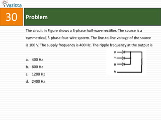
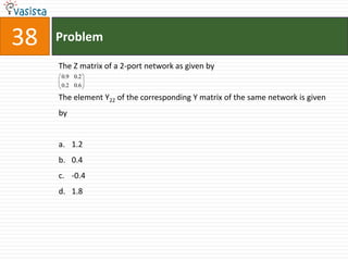
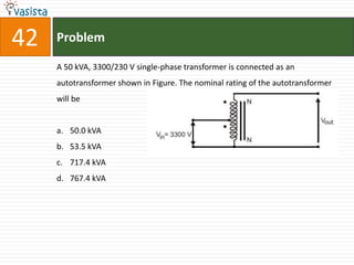

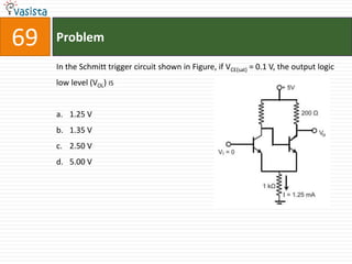
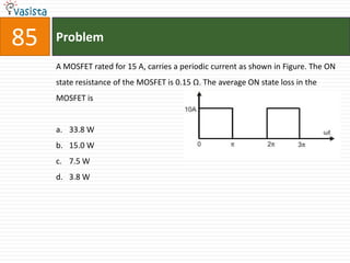
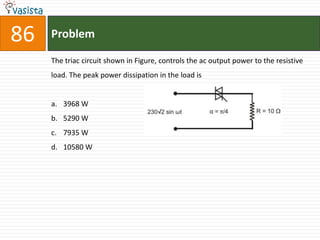
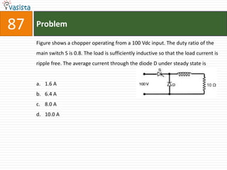
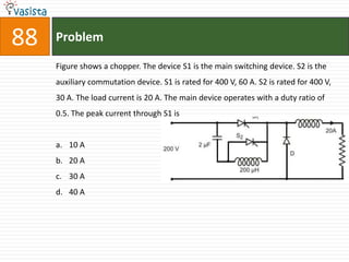
![55 Problem
A new generator having Eg = 1.4 |30° pu [equivalent to (1.212 + j0.70) pu] and
synchronous reactance 'Xs' of 1.0 pu on the system base, is to be connected to a
bus having voltage Vt in the existing power system. This existing power system
can be represented by Thevenin's voltage Eth = 0.9101 pu in series with
Thevenin's impedance Zth = 0.25 |90° pu. The magnitude of the bus voltage Vt
of the system in pu will be
a. 0.990
b. 0.973
c. 0.963
d. 0.900](https://image.slidesharecdn.com/2004-120119224350-phpapp02/85/Electrical-Engineering-2004-Unsolved-Paper-57-320.jpg)