Download to read offline
![International Research Journal of Engineering and Technology (IRJET) e-ISSN: 2395 -0056
Volume: 03 Issue: 02 | Feb-2016 www.irjet.net p-ISSN: 2395-0072
© 2016, IRJET | Impact Factor value: 4.45 | ISO 9001:2008 Certified Journal | Page 599
5. ADVANTAGES OF PENDULUM GENERATOR
i) It can be used in remote areas where power supply
is not available.
ii) It does not require no running cost because it does
not required any fuel.
iii) It can installed in any place quickly as compare to
solar, wind and other type of plant
iv) It is portable; it can be use as portable power
generator.
v) It is simple in construction like other conventional
part.
vi) It required small area for installation
vii) It required less maintains than other power plant.
6. CONCLUSION
With the demand for energy requirements increasing
tremendously, it can be met by alternative energy
resources such as Gravity. Particularly, it can generate
more power compared to the other type of non-
conventional energy.
In addition, this alternative energy source offers
benefits such as easy deploying, low installation cost
and maintenance systems, and less operating cost. In
terms of operational lifetime, installation cost and
reliability, so a Pendulum Power Generator is
considered as a promising alternate for traditional
power sources.
REFERENCES
[1.] S.Nithiya, K.Sadhuna, A. Saravanan.” Energy
Harvesting Using Oscillating Pendulum”,
International Journal for Research and
Development in Engineering (IJRDE), ISSN: 2279-
0500, Special Issue: PP-017-019, 2014.
[2.] Bojan Petkovic.”Modeling and Simulation of a
Double Pendulum with Pad”, Novi Sad, Serbia,
January 2007.
[3.] Nebojša Simin,” Free Energy Of The Oscillating
Pendulum-Lever System”, Novi Sad (Serbia),
September 11, 2007
[4.] Jovan Marjanovic,” The Secret of Free Energy
from the Pendulum”, Veljko Milkovic Research &
Development Center, May 05, 2011, Novi Sad,
Serbia
[5.] Veljko Milkovic “Two-Stage Mechanical Oscillator”,
Veljko Milkovic Research & Development Center,
November 09, 2011, Novi Sad, Serbia.
[6.] “Solar -Magnet Powered Pendulum” Veljko
Milkovic Research & Development Center,
November 09, 2011, Novi Sad, Serbia.
[7.] B.C. Boren, "On the Modeling and Control of
Horizontal Pendulum Wave Energy”, Oregon State
University.
[8.] Thorsen M. Wehr, “Generating Electricity through
Induction Using a Magnetic Field to Power a
Pendulum”
[9.] Rakesh Chaudhari, “Fabrication of Device for
Generation of Energy using two Stage Mechanical
Oscillators”, International Journal for Scientific
Research & Development, Vol. 3, Issue 05, 2015,
ISSN (online): 2321-0613.
[10.] Md.Muqtar Ahmed, Heena Naaz, “Power Generation
through Gravity and Kinetic Energy”, International
Journal of Scientific and Research Publications,
Volume 4, Issue 1, January 2014 15, ISSN 2250-
3153
[11.] K.J. As stroKm, K. Furuta," Swinging up a pendulum
by energy control”, Automatica 36 (2000) 287-295
[12.] S. M. Dhavale, N. M. Kulkarni and A. D. Shaligram,
“Development of Self Powered Energy Harvesting
System for Mobile Health Monitoring”,
International Journal of Research in Advent
Technology (E-ISSN: 2321-9637) Special Issue,
National Conference “ACGT 2015”, 13-14 February
2015
[13.] Eugene I. Butikov, “On the dynamic stabilization of
an inverted pendulum”, Am J. Phys, Vol 69, No. 6,
June 2011.
[14.] Two stage Oscillation”http://www.pendulum-
lever.com/applications.html#generator”
[15.] Physical Magnet Data,
”http://www.supermagnet.de/eng/data_table.php”](https://image.slidesharecdn.com/irjet-v3i2102-171025085121/75/Electrical-Energy-Harvesting-By-Using-Pendulum-Power-Generator-5-2048.jpg)

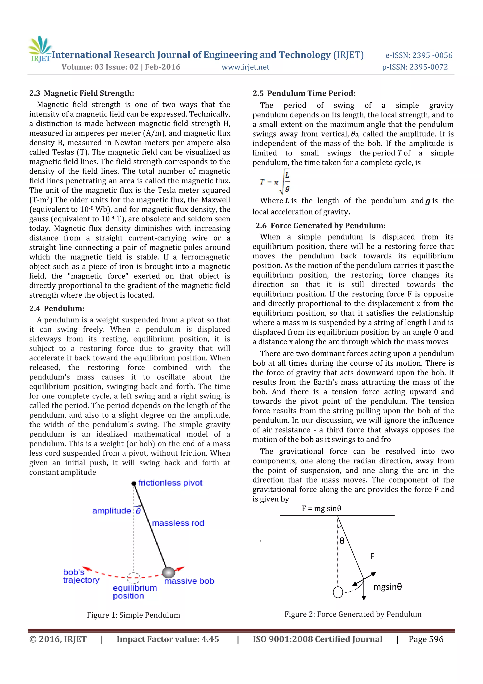
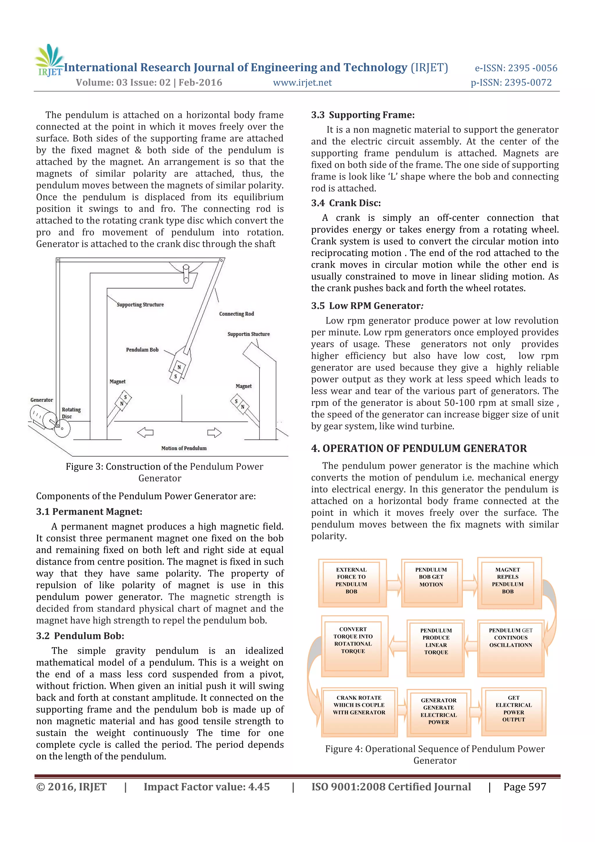
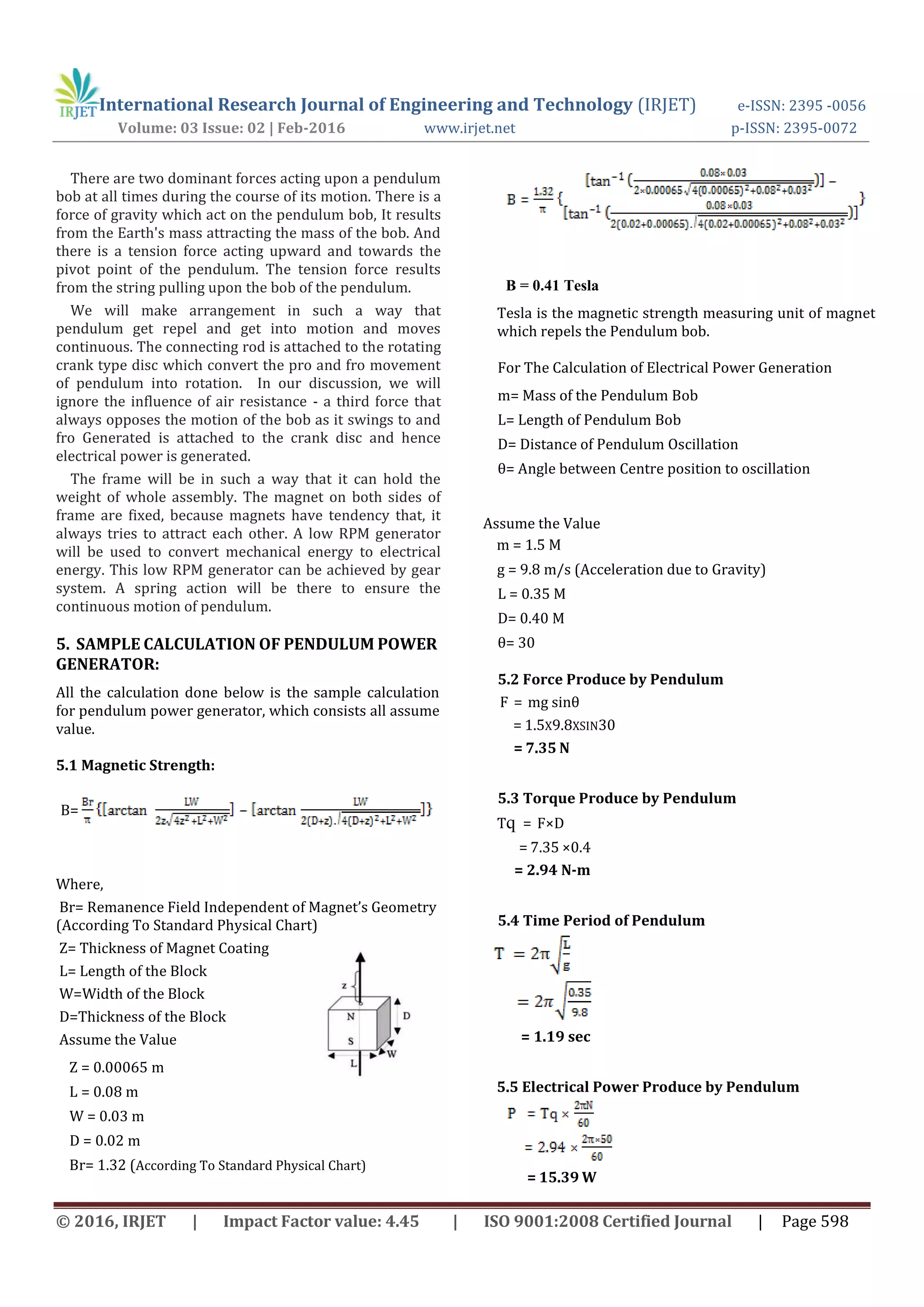
This document describes a pendulum power generator that converts the oscillating motion of a pendulum into electrical energy. The pendulum is attached to a supporting frame and suspended between two magnets of the same polarity. When displaced and released, the pendulum oscillates back and forth due to gravitational restoring forces. A connecting rod transfers the pendulum's linear motion to a crank disc, which converts it into rotational motion. The rotating crank is coupled to a low RPM generator to produce electricity. Sample calculations estimate the magnetic field strength of the magnets, force generated by the pendulum, torque produced, oscillation period, and electrical power output of 15.39 watts. The pendulum power generator provides a renewable energy source


