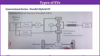
Electric Vehicle (EV) technology architecture refers to the overall design and integration of electrical, electronic, mechanical, and software systems that enable a vehicle to operate using electric power instead of an internal combustion engine (ICE). The architecture defines how energy is stored, managed, converted, and delivered to propel the vehicle efficiently and safely.
![12/02/2026 1
EEE
SRI RAMAKRISHNA ENGINEERING COLLEGE
[Educational Service: SNR Sons Charitable Trust]
[Autonomous Institution, Accredited by NAAC with ‘A’ Grade]
[Approved by AICTE and Permanently Affiliated to Anna University, Chennai]
[ISO 9001:2015 Certified and all eligible programmes Accredited by NBA]
Vattamalaipalayam, N.G.G.O. Colony Post, Coimbatore – 641 022.
Department of Electrical and Electronics Engineering
20EE217 ELECTRIC VEHICLE TECHNOLOGY
Prepared by:
Mr.B.Sridhar, AP(Sl.G)/EEE](https://image.slidesharecdn.com/electricvehicletechnologyarchitecture-260212053347-c0800865/85/Electric-Vehicle-Technology-Architecture-pptx-1-320.jpg)
![12/02/2026 1
EEE
SRI RAMAKRISHNA ENGINEERING COLLEGE
[Educational Service: SNR Sons Charitable Trust]
[Autonomous Institution, Accredited by NAAC with ‘A’ Grade]
[Approved by AICTE and Permanently Affiliated to Anna University, Chennai]
[ISO 9001:2015 Certified and all eligible programmes Accredited by NBA]
Vattamalaipalayam, N.G.G.O. Colony Post, Coimbatore – 641 022.
Department of Electrical and Electronics Engineering
20EE217 ELECTRIC VEHICLE TECHNOLOGY
Prepared by:
Mr.B.Sridhar, AP(Sl.G)/EEE](https://image.slidesharecdn.com/electricvehicletechnologyarchitecture-260212053347-c0800865/75/Electric-Vehicle-Technology-Architecture-pptx-1-2048.jpg)
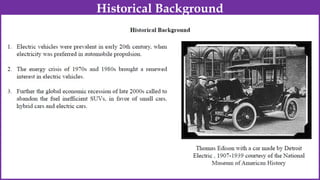
![ Electric Carriage and Wagon Company, US 1894 “Electrobat”.
Pope manufacturing company, US 500 EVs by 1898 “Columbia”.
Riker Electric Motor Company, US “Victoria” in 1897.
London Electric Cab Company, England in 1897.
Bouquet, Garcin and Schivre (BGS), France [1899-1906].
BGS EVs in 1900 had world record of 290 Km/charge.
An EV named “Jamais Contente” captured a record of 110 Km/Hr in 1899.
By 1912, nearly 34,000 EVs were registered in US.
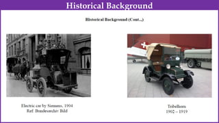
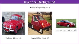
Historical Background](https://image.slidesharecdn.com/electricvehicletechnologyarchitecture-260212053347-c0800865/85/Electric-Vehicle-Technology-Architecture-pptx-3-320.jpg)
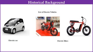
![• Popular EVs in 1990s/Early 2000
– GM EV1 [100 KW, IM, VRLA, 0-100 Km/hr in 9 sec, 144 Km]
– Nissan Altera EV [62 KW, PMSM, Co-Li, 120 Km/hr, 192 Km]
– NIES Luciole [72 KW, In-wheel PMSM, VRLA, 130 Km/hr, Solar]
– HKU-U2001 [45 KW, PMSM, Ni Cd, 110 Km/hr, 176 Km]
– Reva [13 KW, SE DC, VRLA, 65 Km/hr, 80 Km]
• Popular HEVs in 1990s
Toyota Prius [52 KW, ICE, 33 KW PMSM, Ni mH, 160 Km/hr]
Honda Insight [50 KW, ICE, 10 KW PMSM, Ni mH, 26-30 Km/L]
• Popular FCEV in 1990s/early 2000
Toyota Prius [52 KW, ICE, 33 KW PMSM, Ni mH, 160 Km/hr]
Honda Insight [50 KW, ICE, 10 KW PMSM, Ni mH, 26-30 Km/L]
Historical Background](https://image.slidesharecdn.com/electricvehicletechnologyarchitecture-260212053347-c0800865/85/Electric-Vehicle-Technology-Architecture-pptx-14-320.jpg)
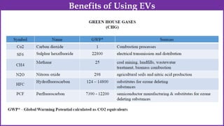
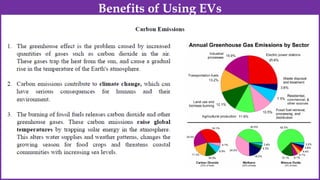
![• Pollutants and Greenhouse Gases
• Particulate Matter (PMx)
• CO, CO2
• CH4
• NOx [N2O, NO and NO2]
• Volatile Organic Compound (VOC)
• Total Hydrocarbon
• Sox [SO2]
Benefits of Using EVs](https://image.slidesharecdn.com/electricvehicletechnologyarchitecture-260212053347-c0800865/85/Electric-Vehicle-Technology-Architecture-pptx-18-320.jpg)