Download as PDF, PPTX


![Load Combinations Concepts
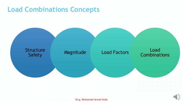
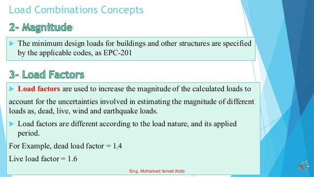
Structures and structural members must always be designed
to carry some reserve load above what is expected under
normal use.
There are three main reasons why some sort of safety factor
is necessary in structural design.
[1] Variability in resistance.
[2] Variability in loading.
[3] Consequences of failure
Eng. Mohamed Ismail Kotb](https://image.slidesharecdn.com/ecp-201ch-220411223408/95/ECP-201_-Ch-2-Load-combinations-ASD-LRFD-_Lecture-2-pdf-6-638.jpg)
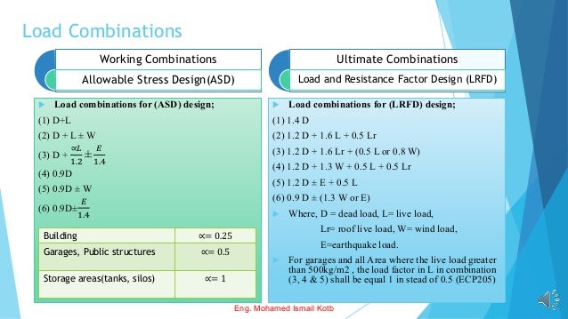

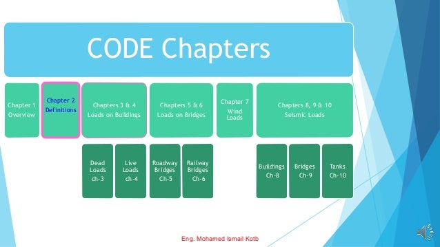
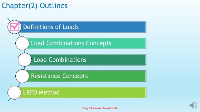
The document outlines the Egyptian Code for Loads (ECP-201) detailing various load types on buildings and bridges, including dead, live, wind, and seismic loads. It emphasizes the importance of safety factors and load combinations in structural design to ensure safety and reliability. Additionally, it describes two design methods: Allowable Stress Design (ASD) and Load and Resistance Factor Design (LRFD), including their respective load combinations.