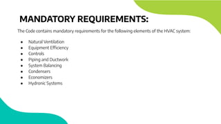
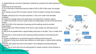
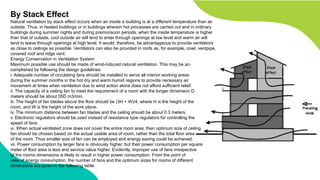
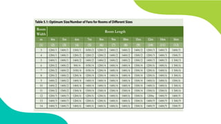
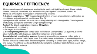
HEAT, VENTILATION
& AIR CONDITIONING
(UNDER ENERGY CONSERVATION AND BUILDING CODE)
INTRODUCTION:
● Heating, Ventilation and Air Conditioning (HVAC) refers
to the equipment, distribution systems, and terminals
that provide, either collectively or individually, the
heating, ventilation, or air-conditioning requirement to a
building or a portion of building
● HVAC energy use in a commercial building can
increase/decrease significantly depending on how
efficiently the combination of air side systems and
central plant operates.
● Proven technologies and design concepts can be used to
build energy efficiencies in the system and generate
significant energy and cost savings.
WHY USE HVAC ?
● HVAC systems also affect the health, comfort, and productivity of occupants. Issues like user
discomfort, improper ventilation, lack of air movement and poor indoor air quality, and poor
acoustic design are linked to HVAC system design and operation and can be improved.
● The best HVAC design considers all the interrelated building systems while addressing indoor
air quality, thermal comfort, energy consumption, and environmental benefits
Basic components of the system include:
● a compressor,
● condenser (air-cooled or water cooled),
● evaporator
● an expansion device, similar to that of a domestic refrigerator.
CONDITIONING SYSTEM BASICS:
● Room air is drawn across an indoor coil called the evaporator that cools and dehumidifies
the air during the cooling cycle.
● The condenser condenses the refrigerant and transforms the high pressure vapor into
high Pressure liquid.
● Heat is rejected via air drawn across the condenser coils using fans (air-cooled condenser) or
using a shell and tube heat exchanger in conjunction with a condenser water reticulation
system and cooling towers (water cooled condenser).
● The expansion device transforms the high pressure high temperature liquid refrigerant
to low pressure low temperature mixture of refrigerant liquid and vapor.
● This mixture fully evaporates in the evaporator absorbing the heat from the water (cooling the
water in a chilled water system) or cooling the air drawn across the coil (direct expansion
system).
● The compressor then raises the pressure and temperature of the refrigerant and the
cycle continues on.
HEATING SYSTEMS:
● Heating system types can be classified fairly well by the heating equipment type. The heating
equipment used in buildings includes boilers (oil and gas), furnaces (oil, gas, and electric), heat pumps,
and space heaters.
● Boiler-based heating systems have steam and/or water piping to distribute heat.
● Boilers can be self-contained units, or they can be packaged units which are factory-built systems,
disassembled for shipment, and reassembled at the site.
● The heated water may serve preheat coils in air handling units; reheat coils, and local radiators.
Systems that circulate water or a fluid are called hydronic systems.
● Heating water may also be used for heating of service water and other process needs, depending on
the building type.
● Some central systems have steam boilers rather than hot water boilers because of the need for steam
for conditioning needs (humidifiers in air-handling units) or process needs (sterilizers in hospitals,
direct-injection heating in laundries and dishwashers, etc.).
● The remaining heating systems include heat pumps and space heaters that heat directly and require
little or no distribution.
MANDATORY REQUIREMENTS:
The Code contains mandatory requirements for the following elements of the HVAC system:
● Natural Ventilation
● Equipment Efficiency
● Controls
● Piping and Ductwork
● System Balancing
● Condensers
● Economizers
● Hydronic Systems
NATURAL VENTILATION
By Wind Action
i. Building need not necessarily be oriented perpendicular to the prevailing outdoor wind; it may
be oriented at any convenient angle between 0° and 30° without losing any beneficial aspect of
the breeze. If the prevailing wind is from east or west, building may be oriented at 45° to the
incident wind so as to diminish the solar heat without much reduction in air motion indoors.
ii. Inlet openings in the buildings should be well distributed and should be located on the windward
side at a low level, and outlet openings should be located on the leeward side. Inlet and outlet
openings at high levels may only clear the top air at that level without producing air movement
at the level of occupancy.
iii. Maximum air movement at a particular plane is achieved by keeping the sill height of the
opening at 85% of the critical height (such as head level) for the following recommended levels
of occupancy:
1. For sitting on chair 0.75 m
2. For sitting on bed 0.60 m
3. For sitting on floor 0.40 m
iv. Inlet openings should not, as far as possAible, be obstructed by adjoining buildings, trees, sign
boards or other obstructions or by partitions inside in the path of air flow.
v. In rooms of normal size having identical windows on opposite walls the average indoor air
speed increases rapidly by increasing the width of the window up to two-thirds of the wall width;
beyond that the increase is in much smaller proportion than the increase of the window width.
The air motion in the working zone is maximum when window height is 1.1 m. Further increase
in window height promotes air motion at higher level of window, but does not contribute
additional benefits as regards air motion in the occupancy zones in buildings.
vi. Greatest flow per unit area of openings is obtained by using inlet and outlet openings of
nearby
equal areas at the same level.
vii. For a total area of openings (inlet and outlet) of 20% to 30% of floor area, the average
indoor
wind velocity is around 30% of outdoor velocity. Further increase in window size increases
the
available velocity but not in the same proportion. In fact, even under most favorable
conditions
the maximum average indoor wind speed does not exceed 40% of outdoor velocity.
viii. Where the direction of wind is quite constant and dependable, the size of the inlet should
be kept
within 30 to 50% of the total area of openings and the building should be oriented
perpendicular
to the incident wind. Where direction of the wind is quite variable, the openings may be
arranged
so that as far as possible there is approximately equal area on all sides. Thus no matter what
the
wind direction is, there would be some openings directly exposed to wind pressure and
others to
air suction and effective air movement through the building would be assured.
ix. Windows of living rooms should open directly to an open space. In places where building
sites are
restricted, open space may have to be created in the buildings by providing adequate
courtyards.
x. In the case of rooms with only one wall exposed to outside, provision of two windows on
that
wall is preferred to that of a single window.
By Stack Effect
Natural ventilation by stack effect occurs when air inside a building is at a different temperature than air
outside. Thus, in heated buildings or in buildings wherein hot processes are carried out and in ordinary
buildings during summer nights and during premonsoon periods, when the inside temperature is higher
than that of outside, cool outside air will tend to enter through openings at low level and warm air will
tend to leave through openings at high level. It would, therefore, be advantageous to provide ventilators
as close to ceilings as possible. Ventilators can also be provided in roofs as, for example, cowl, ventpipe,
covered roof and ridge vent.
Energy Conservation in Ventilation System
Maximum possible use should be made of wind-induced natural ventilation. This may be ac-
complished by following the design guidelines
i. Adequate number of circulating fans should be installed to serve all interior working areas
during the summer months in the hot dry and warm humid regions to provide necessary air
movement at times when ventilation due to wind action alone does not afford sufficient relief.
ii. The capacity of a ceiling fan to meet the requirement of a room with the longer dimension D
meters should be about 55D m3/min.
iii. The height of fan blades above the floor should be (3H + W)/4, where H is the height of the
room, and W is the height of the work plane.
iv. The minimum distance between fan blades and the ceiling should be about 0.3 meters.
v. Electronic regulators should be used instead of resistance type regulators for controlling the
speed of fans.
vi. When actual ventilated zone does not cover the entire room area, then optimum size of ceiling
fan should be chosen based on the actual usable area of room, rather than the total floor area
of the room. Thus smaller size of fan can be employed and energy saving could be achieved.
vii. Power consumption by larger fans is obviously higher, but their power consumption per square
meter of floor area is less and service value higher. Evidently, improper use of fans irrespective
of the rooms dimensions is likely to result in higher power consumption. From the point of
view of energy consumption, the number of fans and the optimum sizes for rooms of different
dimensions are given in the following table:
EQUIPMENT EFFICIENCY:
Minimum equipment efficiencies are required to be met for all HVAC equipment. These include
chillers, unitary air conditioner, split air conditioner, packaged air conditioner, boilers, etc.
There are primarily two main types of air conditioning systems:
1. A direct expansion or “DX” type system in the form of room air conditioners, split system air
conditioners and packaged air conditioners. The DX
type systems offer localized solutions for a building’s heating and cooling needs. These systems
are typically appropriate for smaller (single-zone) buildings.
Parts of the direct expansion system or DX system
a.Split-system air conditioning
b.Packaged air conditioners
2. Central plant system uses chilled water recirculation. Compared to a DX systems, a central
plant HVAC will be able to provide better thermal comfort and flexibility.
Central plant air conditioning systems: In central air-conditioning systems, chilled water is
generated via a central chilled water plant. The chilled water is distributed to air-handling units or
fan-coil units via a chilled water reticulation system consisting of chilled water pipes, valves, fittings,
and pumps. The chillers used in central chilled water plants include air-cooled chillers as well as
water-cooled chiller systems.
WHAT IS A CHILLER
A chiller is essentially a packaged vapor compression cooling machine. The chiller rejects
heat either to condenser water (in the case of a water-cooled chiller) or to ambient air (in
the case of an air-cooled chiller). Water-cooled chillers incorporate the use of cooling
towers, which improve heat rejection more efficiently at the condenser than air-cooled
chillers. For a water-cooled chiller, the cooling tower rejects heat to the environment
through direct heat exchange between the condenser water and cooling air. For an
air-cooled chiller, condenser fans move air through a condenser coil. As heat loads
increase, water-cooled chillers are more energy-efficient than air-cooled chillers.
ENERGY EFFICIENCY TERMS
Coefficient of Performance (COP) – Cooling
The ratio of the rate of heat removal to the rate of energy input, in consistent units, for a complete refrigerating system
or some specific portion of that system under designated operating conditions
Coefficient of Performance (COP) – Heating
The ratio of the rate of heat delivered to the rate of energy input, in consistent units, for a complete heat pump system,
including the compressor and, if applicable, auxiliary heat, under designated operating conditions
Energy Efficiency Ratio (EER)-The ratio of net cooling capacity in BTU/hr to total rate of electric input in watts under
designated operating conditions.
Integrated Part-Load Value (IPLV)-A single number figure of merit based on part-load EER, COP, or KW/ton
expressing part-load efficiency for air-conditioning and heat pump equipment on the basis of weighted operation at
various load capacities for the equipment.
DIFFERENT TYPES OF CHILLER
Chillers are classified according to compressor type. Electric chillers for commercial comfort cooling
have centrifugal, screw, scroll, or reciprocating compressors. Centrifugal and screw chillers have
one or two compressors. Scroll and reciprocating chillers are built with multiple, smaller
compressors.
• Centrifugal chillers are the quiet, efficient, and reliable workhorses of comfort cooling. Although
centrifugal chillers are available as small as 70 tons, most are 300 tons or larger.
• Screw chillers are up to 40% smaller and lighter than centrifugal chillers, so are becoming popular
as replacement chillers.
• Scroll compressors are rotary positive-displacement machines, also fairly new to the comfort cool-
ing market. These small compressors are efficient, quiet, and reliable. Scroll compressors are made
in sizes of 1.5 to 15 tons.
CONTROLS
Controls are one of the most critical element for improving efficiency of HVAC system. Controls determine how
HVAC systems should operate to meet the design goals o comfort,and cost efficient operation.
THIS CODE SPECIFIES THE CONTROLS:
1. TIMELOCK CONTROL
All mechanical cooling and heating systems shall be controlled by a timelock that
a. Can start and stop the system under different schedules for three different day types per week.
b. Is capable of retaining programming and time setting during loss of power for a period for at least 10 hours
c. Includes an accessible manual override that allows temporary operation of the system for up to 2 hours.
Exceptions to the above are:
a. Cooling systems < 28 kW (8 tons)
b. Heating systems < 7 kW (2 tons)
2. TEMPERATURE CONTROL:
All heating and cooling equipment shall be temperature controlled. Where a unit provides both heating and
cooling, controls shall be capable of providing a temperature dead band of 3°C (5°F) within which the supply
of heating and cooling energy to the zone is shut off or reduced to a minimum. Where separate heating and
cooling equipment serve the same temperature zone, thermostats shall be interlocked to prevent simultaneous
heating and cooling.
Controls for Cooling Towers and Closed Circuit Fluid Coolers
All cooling towers and closed circuit fluid coolers shall have either two speed motors, pony motors, or variable
speed drives controlling the fan
PIPING AND DUCTWORK
Pipe insulation
To minimize heat losses, the Code requires that piping of heating and cooling systems, (including the storage
tanks,) must be insulated. The Code specifies required R-values of insulation for heating and cooling systems
based on the operating temperature of the system
DUCTWORK
PROVIDES R VALUES
SYSTEM BALANCING
System balancing is a process for maintaining the performance of an HVAC system, and for providing the
occupants
with a comfortable conditioned space. Balancing an air or water-based HVAC system of buildings will make
it more
energy-efficient, provide improved thermal comfort, extend the life of the building equipment and reduce
the cost of
operating it.
AIR SYSTEM BALANCING
Air System Balancing refers to the adjustment of airflow rates through air distribution system devices, such
as fans and diffusers. This is done by adjusting the position of dampers, splitter vanes, extractors, etc.,
manually or By using automatic control devices, such as constant air volume or variable air volume boxes.
Balancing is necessary to verify that each space served by a system receives the air volume designed for
that space. Proper means for air balancing should be installed at each supply air outlet and zone terminal
device.
These include balancing dampers or other means of supply-air adjustment provided in the branch ducts or
at each individual duct register, grille, or diffuser.
CONDENSER
A condenser is a heat exchanger that liquefies refrigerant
vapor through heat removal. The typical condensing unit
houses a compressor, a condenser fan motor, and coils, along
with controls which make all the components work
sequentially.
Condensers should be located in such a manner that there is
no restriction to the air flow around the condenser
coils, there is no short-circuiting of discharge air to the intake
side, and the heat discharge of other adjacent
equipment is not anywhere the air intake of the condenser.
Treated Water for Condensers
Condenser water treatment is important to eliminate mineral
buildup in condensers and chilled water systems.
Mineral deposits create poor heat transfer situations there by
reducing the efficiency of the unit.
Prescriptive Requirements
a. Serves a single zone
b. Cooling (if any) is provided by a unitary packaged or split-system air conditioner or heat pump
c. Heating (if any) is provided by a unitary packaged or split-system heat pump, fuel-fired furnace, electric
resistance heater, or baseboards connected to a boiler.
Single Zone for HVAC
As per the Code, HVAC Zone is a space or group of spaces within a building with heating and cooling
requirements that are sufficiently similar so that desired conditions (e.g., temperature) can be maintained
throughout using a single sensor (e.g., thermostat or temperature sensor).
Heat Pump
A heat pump consists of one or more factory-made assemblies that normally include indoor conditioning
coil, compressor, and outdoor coil, including means to provide a heating function. Heat pumps provide the
function of air heating with controlled temperature, and may include the functions of air cooling.
ECONOMIZERS
Economizers allow the use of outdoor air to cool the building when the outside temperature is cooler than
that inside. An economizer consists of dampers, sensors, actuators, and logic devices that together decide
how much outside air to bring into a building (See Figure 5.2).Under the right conditions, sensors and
controls shut down the compressor and bring in the outside air through the economizer louvers. A properly
operating economizer can cut energy costs by as much as 10% of a building’s total energy consumption,
depending mostly on local climate and internal cooling loads.
Air Economizer
An air economizer is duct and damper arrangement and automatic control system
that together allow a
cooling system to supply outdoor air to reduce or eliminate the need for
mechanical cooling during mild or
cold weather.
Water Economizer
A water economizer is a system by which the supply air of a cooling system is
cooled indirectly with water that
is itself cooled by heat or mass transfer to the environment without the use of
mechanical cooling.
PARTIAL COOLING
Partial Cooling
One can use the building’s intrinsic thermal mass to reduce peak cooling
loads by circulating cool night-time air
to pre-cool the building prior to daily occupancy in the cooling season. The
building control system can operate
ventilation fans in the economizer mode on a scheduled basis. Care
should be taken to prevent excessive fan
operation that would offset cooling energy savings. It is also ensured that
night humidity does not preclude the
use of this strategy.
HYDRONIC SYSTEM BALANCING
Hydronic System Balancing refers to the adjustment of water
flow rates through distribution system devices such as pumps
and coils, by manually adjusting the position of valves, or by
using automatic control devices, such as flow control valves.
When something is balanced, it is even on both sides.
Therefore, a balanced hydronic system is one that delivers
even flow to all of the devices on that piping system. Each
component has an effective equal length of pipe on the supply
and return. And when a system is balanced, all of the pressure
drops are correct for the devices. When that happens, the
highest efficiencies are possible in the system. One need not
have to change system supply temperatures to accommodate
one zone only. The system has the least amount of pressure
drop possible, which translates into reduced pumping costs. A
balanced hydronic system is one that is efficient. If a system
that is not delivering the water to the right devices in the right
amounts, then the system is out of balance.
THANK YOU

ecbc codes for hvuc

  • 1.
    HEAT, VENTILATION & AIRCONDITIONING (UNDER ENERGY CONSERVATION AND BUILDING CODE)
  • 2.
    INTRODUCTION: ● Heating, Ventilationand Air Conditioning (HVAC) refers to the equipment, distribution systems, and terminals that provide, either collectively or individually, the heating, ventilation, or air-conditioning requirement to a building or a portion of building ● HVAC energy use in a commercial building can increase/decrease significantly depending on how efficiently the combination of air side systems and central plant operates. ● Proven technologies and design concepts can be used to build energy efficiencies in the system and generate significant energy and cost savings.
  • 3.
    WHY USE HVAC? ● HVAC systems also affect the health, comfort, and productivity of occupants. Issues like user discomfort, improper ventilation, lack of air movement and poor indoor air quality, and poor acoustic design are linked to HVAC system design and operation and can be improved. ● The best HVAC design considers all the interrelated building systems while addressing indoor air quality, thermal comfort, energy consumption, and environmental benefits Basic components of the system include: ● a compressor, ● condenser (air-cooled or water cooled), ● evaporator ● an expansion device, similar to that of a domestic refrigerator.
  • 4.
    CONDITIONING SYSTEM BASICS: ●Room air is drawn across an indoor coil called the evaporator that cools and dehumidifies the air during the cooling cycle. ● The condenser condenses the refrigerant and transforms the high pressure vapor into high Pressure liquid. ● Heat is rejected via air drawn across the condenser coils using fans (air-cooled condenser) or using a shell and tube heat exchanger in conjunction with a condenser water reticulation system and cooling towers (water cooled condenser). ● The expansion device transforms the high pressure high temperature liquid refrigerant to low pressure low temperature mixture of refrigerant liquid and vapor. ● This mixture fully evaporates in the evaporator absorbing the heat from the water (cooling the water in a chilled water system) or cooling the air drawn across the coil (direct expansion system). ● The compressor then raises the pressure and temperature of the refrigerant and the cycle continues on.
  • 6.
    HEATING SYSTEMS: ● Heatingsystem types can be classified fairly well by the heating equipment type. The heating equipment used in buildings includes boilers (oil and gas), furnaces (oil, gas, and electric), heat pumps, and space heaters. ● Boiler-based heating systems have steam and/or water piping to distribute heat. ● Boilers can be self-contained units, or they can be packaged units which are factory-built systems, disassembled for shipment, and reassembled at the site. ● The heated water may serve preheat coils in air handling units; reheat coils, and local radiators. Systems that circulate water or a fluid are called hydronic systems. ● Heating water may also be used for heating of service water and other process needs, depending on the building type. ● Some central systems have steam boilers rather than hot water boilers because of the need for steam for conditioning needs (humidifiers in air-handling units) or process needs (sterilizers in hospitals, direct-injection heating in laundries and dishwashers, etc.). ● The remaining heating systems include heat pumps and space heaters that heat directly and require little or no distribution.
  • 7.
    MANDATORY REQUIREMENTS: The Codecontains mandatory requirements for the following elements of the HVAC system: ● Natural Ventilation ● Equipment Efficiency ● Controls ● Piping and Ductwork ● System Balancing ● Condensers ● Economizers ● Hydronic Systems
  • 8.
    NATURAL VENTILATION By WindAction i. Building need not necessarily be oriented perpendicular to the prevailing outdoor wind; it may be oriented at any convenient angle between 0° and 30° without losing any beneficial aspect of the breeze. If the prevailing wind is from east or west, building may be oriented at 45° to the incident wind so as to diminish the solar heat without much reduction in air motion indoors. ii. Inlet openings in the buildings should be well distributed and should be located on the windward side at a low level, and outlet openings should be located on the leeward side. Inlet and outlet openings at high levels may only clear the top air at that level without producing air movement at the level of occupancy. iii. Maximum air movement at a particular plane is achieved by keeping the sill height of the opening at 85% of the critical height (such as head level) for the following recommended levels of occupancy: 1. For sitting on chair 0.75 m 2. For sitting on bed 0.60 m 3. For sitting on floor 0.40 m iv. Inlet openings should not, as far as possAible, be obstructed by adjoining buildings, trees, sign boards or other obstructions or by partitions inside in the path of air flow. v. In rooms of normal size having identical windows on opposite walls the average indoor air speed increases rapidly by increasing the width of the window up to two-thirds of the wall width; beyond that the increase is in much smaller proportion than the increase of the window width. The air motion in the working zone is maximum when window height is 1.1 m. Further increase in window height promotes air motion at higher level of window, but does not contribute additional benefits as regards air motion in the occupancy zones in buildings.
  • 9.
    vi. Greatest flowper unit area of openings is obtained by using inlet and outlet openings of nearby equal areas at the same level. vii. For a total area of openings (inlet and outlet) of 20% to 30% of floor area, the average indoor wind velocity is around 30% of outdoor velocity. Further increase in window size increases the available velocity but not in the same proportion. In fact, even under most favorable conditions the maximum average indoor wind speed does not exceed 40% of outdoor velocity. viii. Where the direction of wind is quite constant and dependable, the size of the inlet should be kept within 30 to 50% of the total area of openings and the building should be oriented perpendicular to the incident wind. Where direction of the wind is quite variable, the openings may be arranged so that as far as possible there is approximately equal area on all sides. Thus no matter what the wind direction is, there would be some openings directly exposed to wind pressure and others to air suction and effective air movement through the building would be assured. ix. Windows of living rooms should open directly to an open space. In places where building sites are restricted, open space may have to be created in the buildings by providing adequate courtyards. x. In the case of rooms with only one wall exposed to outside, provision of two windows on that wall is preferred to that of a single window.
  • 10.
    By Stack Effect Naturalventilation by stack effect occurs when air inside a building is at a different temperature than air outside. Thus, in heated buildings or in buildings wherein hot processes are carried out and in ordinary buildings during summer nights and during premonsoon periods, when the inside temperature is higher than that of outside, cool outside air will tend to enter through openings at low level and warm air will tend to leave through openings at high level. It would, therefore, be advantageous to provide ventilators as close to ceilings as possible. Ventilators can also be provided in roofs as, for example, cowl, ventpipe, covered roof and ridge vent. Energy Conservation in Ventilation System Maximum possible use should be made of wind-induced natural ventilation. This may be ac- complished by following the design guidelines i. Adequate number of circulating fans should be installed to serve all interior working areas during the summer months in the hot dry and warm humid regions to provide necessary air movement at times when ventilation due to wind action alone does not afford sufficient relief. ii. The capacity of a ceiling fan to meet the requirement of a room with the longer dimension D meters should be about 55D m3/min. iii. The height of fan blades above the floor should be (3H + W)/4, where H is the height of the room, and W is the height of the work plane. iv. The minimum distance between fan blades and the ceiling should be about 0.3 meters. v. Electronic regulators should be used instead of resistance type regulators for controlling the speed of fans. vi. When actual ventilated zone does not cover the entire room area, then optimum size of ceiling fan should be chosen based on the actual usable area of room, rather than the total floor area of the room. Thus smaller size of fan can be employed and energy saving could be achieved. vii. Power consumption by larger fans is obviously higher, but their power consumption per square meter of floor area is less and service value higher. Evidently, improper use of fans irrespective of the rooms dimensions is likely to result in higher power consumption. From the point of view of energy consumption, the number of fans and the optimum sizes for rooms of different dimensions are given in the following table:
  • 12.
    EQUIPMENT EFFICIENCY: Minimum equipmentefficiencies are required to be met for all HVAC equipment. These include chillers, unitary air conditioner, split air conditioner, packaged air conditioner, boilers, etc. There are primarily two main types of air conditioning systems: 1. A direct expansion or “DX” type system in the form of room air conditioners, split system air conditioners and packaged air conditioners. The DX type systems offer localized solutions for a building’s heating and cooling needs. These systems are typically appropriate for smaller (single-zone) buildings. Parts of the direct expansion system or DX system a.Split-system air conditioning b.Packaged air conditioners 2. Central plant system uses chilled water recirculation. Compared to a DX systems, a central plant HVAC will be able to provide better thermal comfort and flexibility. Central plant air conditioning systems: In central air-conditioning systems, chilled water is generated via a central chilled water plant. The chilled water is distributed to air-handling units or fan-coil units via a chilled water reticulation system consisting of chilled water pipes, valves, fittings, and pumps. The chillers used in central chilled water plants include air-cooled chillers as well as water-cooled chiller systems.
  • 13.
    WHAT IS ACHILLER A chiller is essentially a packaged vapor compression cooling machine. The chiller rejects heat either to condenser water (in the case of a water-cooled chiller) or to ambient air (in the case of an air-cooled chiller). Water-cooled chillers incorporate the use of cooling towers, which improve heat rejection more efficiently at the condenser than air-cooled chillers. For a water-cooled chiller, the cooling tower rejects heat to the environment through direct heat exchange between the condenser water and cooling air. For an air-cooled chiller, condenser fans move air through a condenser coil. As heat loads increase, water-cooled chillers are more energy-efficient than air-cooled chillers. ENERGY EFFICIENCY TERMS Coefficient of Performance (COP) – Cooling The ratio of the rate of heat removal to the rate of energy input, in consistent units, for a complete refrigerating system or some specific portion of that system under designated operating conditions Coefficient of Performance (COP) – Heating The ratio of the rate of heat delivered to the rate of energy input, in consistent units, for a complete heat pump system, including the compressor and, if applicable, auxiliary heat, under designated operating conditions Energy Efficiency Ratio (EER)-The ratio of net cooling capacity in BTU/hr to total rate of electric input in watts under designated operating conditions. Integrated Part-Load Value (IPLV)-A single number figure of merit based on part-load EER, COP, or KW/ton expressing part-load efficiency for air-conditioning and heat pump equipment on the basis of weighted operation at various load capacities for the equipment.
  • 14.
    DIFFERENT TYPES OFCHILLER Chillers are classified according to compressor type. Electric chillers for commercial comfort cooling have centrifugal, screw, scroll, or reciprocating compressors. Centrifugal and screw chillers have one or two compressors. Scroll and reciprocating chillers are built with multiple, smaller compressors. • Centrifugal chillers are the quiet, efficient, and reliable workhorses of comfort cooling. Although centrifugal chillers are available as small as 70 tons, most are 300 tons or larger. • Screw chillers are up to 40% smaller and lighter than centrifugal chillers, so are becoming popular as replacement chillers. • Scroll compressors are rotary positive-displacement machines, also fairly new to the comfort cool- ing market. These small compressors are efficient, quiet, and reliable. Scroll compressors are made in sizes of 1.5 to 15 tons.
  • 16.
    CONTROLS Controls are oneof the most critical element for improving efficiency of HVAC system. Controls determine how HVAC systems should operate to meet the design goals o comfort,and cost efficient operation. THIS CODE SPECIFIES THE CONTROLS: 1. TIMELOCK CONTROL All mechanical cooling and heating systems shall be controlled by a timelock that a. Can start and stop the system under different schedules for three different day types per week. b. Is capable of retaining programming and time setting during loss of power for a period for at least 10 hours c. Includes an accessible manual override that allows temporary operation of the system for up to 2 hours. Exceptions to the above are: a. Cooling systems < 28 kW (8 tons) b. Heating systems < 7 kW (2 tons) 2. TEMPERATURE CONTROL: All heating and cooling equipment shall be temperature controlled. Where a unit provides both heating and cooling, controls shall be capable of providing a temperature dead band of 3°C (5°F) within which the supply of heating and cooling energy to the zone is shut off or reduced to a minimum. Where separate heating and cooling equipment serve the same temperature zone, thermostats shall be interlocked to prevent simultaneous heating and cooling. Controls for Cooling Towers and Closed Circuit Fluid Coolers All cooling towers and closed circuit fluid coolers shall have either two speed motors, pony motors, or variable speed drives controlling the fan
  • 17.
    PIPING AND DUCTWORK Pipeinsulation To minimize heat losses, the Code requires that piping of heating and cooling systems, (including the storage tanks,) must be insulated. The Code specifies required R-values of insulation for heating and cooling systems based on the operating temperature of the system DUCTWORK PROVIDES R VALUES
  • 18.
    SYSTEM BALANCING System balancingis a process for maintaining the performance of an HVAC system, and for providing the occupants with a comfortable conditioned space. Balancing an air or water-based HVAC system of buildings will make it more energy-efficient, provide improved thermal comfort, extend the life of the building equipment and reduce the cost of operating it. AIR SYSTEM BALANCING Air System Balancing refers to the adjustment of airflow rates through air distribution system devices, such as fans and diffusers. This is done by adjusting the position of dampers, splitter vanes, extractors, etc., manually or By using automatic control devices, such as constant air volume or variable air volume boxes. Balancing is necessary to verify that each space served by a system receives the air volume designed for that space. Proper means for air balancing should be installed at each supply air outlet and zone terminal device. These include balancing dampers or other means of supply-air adjustment provided in the branch ducts or at each individual duct register, grille, or diffuser.
  • 19.
    CONDENSER A condenser isa heat exchanger that liquefies refrigerant vapor through heat removal. The typical condensing unit houses a compressor, a condenser fan motor, and coils, along with controls which make all the components work sequentially. Condensers should be located in such a manner that there is no restriction to the air flow around the condenser coils, there is no short-circuiting of discharge air to the intake side, and the heat discharge of other adjacent equipment is not anywhere the air intake of the condenser. Treated Water for Condensers Condenser water treatment is important to eliminate mineral buildup in condensers and chilled water systems. Mineral deposits create poor heat transfer situations there by reducing the efficiency of the unit.
  • 20.
    Prescriptive Requirements a. Servesa single zone b. Cooling (if any) is provided by a unitary packaged or split-system air conditioner or heat pump c. Heating (if any) is provided by a unitary packaged or split-system heat pump, fuel-fired furnace, electric resistance heater, or baseboards connected to a boiler. Single Zone for HVAC As per the Code, HVAC Zone is a space or group of spaces within a building with heating and cooling requirements that are sufficiently similar so that desired conditions (e.g., temperature) can be maintained throughout using a single sensor (e.g., thermostat or temperature sensor). Heat Pump A heat pump consists of one or more factory-made assemblies that normally include indoor conditioning coil, compressor, and outdoor coil, including means to provide a heating function. Heat pumps provide the function of air heating with controlled temperature, and may include the functions of air cooling.
  • 21.
    ECONOMIZERS Economizers allow theuse of outdoor air to cool the building when the outside temperature is cooler than that inside. An economizer consists of dampers, sensors, actuators, and logic devices that together decide how much outside air to bring into a building (See Figure 5.2).Under the right conditions, sensors and controls shut down the compressor and bring in the outside air through the economizer louvers. A properly operating economizer can cut energy costs by as much as 10% of a building’s total energy consumption, depending mostly on local climate and internal cooling loads. Air Economizer An air economizer is duct and damper arrangement and automatic control system that together allow a cooling system to supply outdoor air to reduce or eliminate the need for mechanical cooling during mild or cold weather. Water Economizer A water economizer is a system by which the supply air of a cooling system is cooled indirectly with water that is itself cooled by heat or mass transfer to the environment without the use of mechanical cooling.
  • 22.
    PARTIAL COOLING Partial Cooling Onecan use the building’s intrinsic thermal mass to reduce peak cooling loads by circulating cool night-time air to pre-cool the building prior to daily occupancy in the cooling season. The building control system can operate ventilation fans in the economizer mode on a scheduled basis. Care should be taken to prevent excessive fan operation that would offset cooling energy savings. It is also ensured that night humidity does not preclude the use of this strategy.
  • 23.
    HYDRONIC SYSTEM BALANCING HydronicSystem Balancing refers to the adjustment of water flow rates through distribution system devices such as pumps and coils, by manually adjusting the position of valves, or by using automatic control devices, such as flow control valves. When something is balanced, it is even on both sides. Therefore, a balanced hydronic system is one that delivers even flow to all of the devices on that piping system. Each component has an effective equal length of pipe on the supply and return. And when a system is balanced, all of the pressure drops are correct for the devices. When that happens, the highest efficiencies are possible in the system. One need not have to change system supply temperatures to accommodate one zone only. The system has the least amount of pressure drop possible, which translates into reduced pumping costs. A balanced hydronic system is one that is efficient. If a system that is not delivering the water to the right devices in the right amounts, then the system is out of balance.
  • 24.