This summary provides information about a Dutch Country Wall Clock CNC project:
- The project involves making front and back panels for a wall clock featuring a Dutch "tole" painting style using VCarve Pro or Aspire software.
- Materials needed include boards for the front and back panels, a clock insert, hardware to hang the clock, and wood finishing supplies.
- The tutorial provides instructions on opening the project files, running the toolpaths, assembling the clock, and applying a finish.
The Paradise Box is a decorative box project featuring an elaborate chip carve motif. It consists of a top, front and back panels, two side panels, and a bottom assembled together. The box dimensions are approximately 131⁄2"W x 91⁄2"D x 51⁄2"H. The project utilizes VCarve Pro or Aspire software and a CNC machine to carve the design into hardwood boards. Detailed instructions are provided on opening the project files, running the toolpaths, assembling the parts, and applying stain and finish.
This document provides instructions for making a decorative Mail Repository project using a CNC machine. The Mail Repository features three mail compartments and can also be used as a plant stand. The project is made from wood boards cut using Vectric software toolpaths. It is then sanded, stained, and finished to resemble antique brass. Directions are provided on assembling the compartments, attaching them to the base, and completing the project.
The document describes how to make decorative gift boxes called Cool Cubes using a CNC machine. It involves cutting slots and grooves on the inside faces of cube panels first before flipping the material to cut designs on the outside faces. The finished cubes measure 4 inches square and users can choose between lift-top lids or hinges. Assembly involves gluing the panels and bottom together before adding the lid and optional finishing touches.
Designing process of printed circuit boardselprocus
Most key element in electronic circuits and equipment’s is the Printed Circuit Board which connects electronic components with conductive lines printed
This document describes the design of a wood picnic table in CATIA. It discusses the process of sketching each individual part like the bottom stand connector, top stand connector, seat bench wood, and table stand. The steps include entering the sketcher workbench, using profiles and constraints to sketch the parts, extruding the sketches to create solid parts, and using operations like mirror to create symmetrical parts. The document concludes that this project exposes students to using CATIA software to design complex assemblies from individual parts and helps develop their CAD/CAM skills for future engineering careers.
William Work gives a presentation on using AutoCAD to create 3D models suitable for 3D printing. He begins with an introduction and outlines what attendees will learn. The presentation covers the basics of 3D printing and best practices for modeling. It demonstrates AutoCAD's 3D tools like solids, extrusions, and booleans. As a case study, it walks through step-by-step creation of a Doric column using techniques demonstrated earlier. It concludes by discussing preparation and output of files for 3D printing.
Soren Shen-Lung Lin, Bridget White, and Steve DeWitt will present on innovative BIM workflows for industrialized construction. Soren is a senior architect specialized in built environment analysis and industrialization methodology. Bridget is a BIM director who implements complex analysis, virtual reality, industrialization, and streamlining information flow between architects and builders. Steve has 20 years of BIM software experience and helped found KitConnect. They will discuss their work on the New Stavanger University Hospital project and introduce V.O.L.U.T.E., a step-by-step BIM workflow they developed.
This document provides instructions for creating a parameterized CATIA V5 model of a joggled extrusion profile using Knowledgeware tools. The steps include:
1. Creating a 2D extrusion profile sketch and assigning variable names to the constraints.
2. Creating a 3D joggled extrusion using the Rib tool and linking it to a spreadsheet with aluminum extrusion dimensions.
3. Developing a macro to automatically update the model based on input dimensions and add checks for company standards.
The goal is to streamline the design process for variations of joggled extrusions by automating the updating of models and drawings.
AutoCAD is a computer-aided drafting software used by engineers to create 2D and 3D designs. It has many tools that allow users to draw various shapes and objects with precision. Users can create floor plans, sections, and elevations of buildings. Objects in AutoCAD can be edited and modified easily. The document provides an introduction and overview of basic AutoCAD tools and functions such as drawing lines, rectangles, circles, and 3D solids. It also discusses the use of different coordinate systems, editing commands, and hatching patterns.
1) The document describes a lab report for a project using Autodesk Inventor and MasterCAM software to design and machine a key chain with a scout logo.
2) The project involved using Inventor to create a 3D model of the key chain from 2D sketches, and then using MasterCAM to generate toolpaths and G-code for CNC machining.
3) The student demonstrated proficiency with both CAD and CAM software, completing all objectives of learning their basic functions and designing and machining a solid model.
The document discusses the process of designing and fabricating a printed circuit board (PCB). It involves preparing the circuit artwork by creating schematic and board files using design software like Eagle. Key steps include selecting and adding parts to the schematic, wiring the parts, arranging components on the board, and using auto-routing to connect the parts on the board layout. Troubleshooting may be needed during the design and fabrication process.
This document provides instructions for Laboratory Assignment 2 of the CMPE 118/218 course. The assignment involves designing, building, and programming a simple motorized platform using SolidWorks, CorelDraw, and a laser cutter. Students must complete three parts: 1) designing the platform components in CAD software, 2) cutting out parts from foamcore or MDF using the laser cutter, and 3) building a working detector circuit to control the motors. The platform must include a base, motor mounts, motors, an H-bridge module, a column, and a top platform. Students work in pairs and are responsible for providing their own materials.
This document provides instructions for Laboratory Assignment 2 for the course CMPE 118/218 Introduction to Mechatronics. The assignment involves designing, building, and programming a simple motorized platform using SolidWorks, CorelDraw, and a laser cutter. Students must complete three parts: 1) designing the platform components in CAD software; 2) cutting out parts from foamcore and MDF using the laser cutter; and 3) building a working detector circuit to control the motors.
hello everyone!
This is an example of how to make an industrial report for your college. By getting through this report you can easily make your own report.
This will help all those who spend a lot of time in browsing or for formats on how to make reports for their industrial training.
I am sure that after watching this report you will get a brief idea on how to make your own one and make it look attractive and purposeful.
Thank You!
The document discusses the importance of drawings in engineering. It states that drawings are effective communication tools that reduce ambiguity. They are used at various stages of engineering projects from design to construction to operations. The document also outlines standards organizations for drawings and different types of drawings like schematics, technical drawings, and 3D models. It describes best practices for drawing offices, such as maintaining uniformity and using standard symbols and dimensions.
This document provides instructions for an assignment on computer-aided design (CAD) drawings for a toy train. The learner must produce an isometric projection drawing of the train and orthographic projection drawings of its components. They must also create an assembly drawing bringing the components together and store, retrieve, and print/plot the CAD drawings. The assignment aims to demonstrate the learner's ability to produce different types of CAD drawings according to British standards and correctly manage engineering drawings. It is assessed against criteria for creating isometric, orthographic, and assembled drawings as well as storing, retrieving, and outputting CAD files.
The document describes various projects Frank Iattarelli has worked on from 2012 to present. They include a 3D dust printer, CNC name plaque, qualification line, cable cutting guide, helical wire guide, and more. The projects utilized various manufacturing methods like SolidWorks, CNC milling, manual machining, 3D printing, and more. Most projects were designed and built to learn new skills, solve problems, or create functional prototypes.
The document describes tutorials included with AutoCAD Civil 3D 2011. There are tutorials for points, surfaces, surveys, alignments, profiles, parcels, grading, corridors, intersections, sections, materials, pipe networks, parts, and plan production. Each tutorial set contains exercises to explore Civil 3D features in a logical sequence based on typical design workflows. The tutorials use provided drawings and data files.
The document provides examples of the author's engineering design and CAD work. It includes summaries of projects involving the UW Hyperloop team developing magnetic propulsion test cells, manufacturing components for the UW EcoCar, 3D printing a hovercraft prototype, designing a test bench lift, molding and casting silicone components, and building a digital light projection printer. The author's roles included CAD modeling, electronics, prototyping, manufacturing, and team leadership. Additional work included logo and graphic designs for clients.
This document describes SPULLOWS, a software tool for designing, modeling, costing, and preparing quotations for metal expansion joints. SPULLOWS allows users to design bellows elements and associated hardware, generate 2D and 3D models, automatically create bills of materials and cost sheets, and reduce the time required for the entire process from over 6 hours to just 20 minutes. The software guides users through the design process, calculates key bellows parameters, and automatically generates scaled drawings, 3D models, and cost reports.
Here are 10 key responsibilities of a civil engineer from beginning to end of the construction project to ensure timely completion:
1. Conduct a site survey and soil testing to analyze the land and foundation requirements.
2. Prepare detailed design drawings showing the architectural, structural, utility plans.
3. Obtain necessary permits and approvals from local authorities.
4. Tender the project and evaluate contractor bids to appoint the most suitable one.
5. Supervise the contractor during site preparation and foundation works.
6. Inspect and approve the installation of underground utilities and stormwater systems.
7. Oversee and inspect the building construction as per the approved plans and specifications.
8. Ensure quality
Here are 10 key responsibilities of a civil engineer from beginning to end of the construction project to ensure timely completion:
1. Conduct a site survey and soil investigation to analyze the land and soil conditions.
2. Prepare the site development plan, building layout, and infrastructure plans like roads, parking, drainage, sewage, water supply etc.
3. Develop a work schedule and cost estimate for approval.
4. Obtain necessary permits from the local authorities.
5. Supervise the foundation work, earthwork and infrastructure development.
6. Monitor the quality of materials and construction techniques.
7. Review and approve contractor's work progress and process payments.
8. Address any design or construction
Here are 10 key responsibilities of a civil engineer from beginning to end of the construction project to ensure timely completion:
1. Conduct a site survey and soil investigation to analyze the land and soil conditions.
2. Prepare the site development plan, building layout, and infrastructure plans like roads, parking, drainage, water supply and sewage systems.
3. Obtain necessary approvals and permits from local authorities.
4. Develop a detailed schedule and cost estimate for efficient project planning and management.
5. Tender the project and evaluate contractor bids to award the work.
6. Supervise the construction to ensure it meets specifications, standards and stays on schedule.
7. Inspect and test infrastructure like
The document provides an introduction to AutoCAD, including its origins and development. It discusses some of AutoCAD's key features like drawing 2D and 3D objects, editing tools, object snapping, zooming and panning. It also covers topics like units systems, paper sizes, hatching, solid modeling, and the difference between the world coordinate system and user coordinate systems. The document serves as an overview guide for learning the basics of using AutoCAD.
➒➌➎➏➑➐➋➑➐➐ Satta Matka Dpboss Matka Guessing Indian Matka Satta Matta Matka KALYAN MATKA | MATKA RESULT | KALYAN MATKA TIPS | SATTA MATKA | MATKA.COM | MATKA PANA JODI TODAY | BATTA SATKA | MATKA PATTI JODI NUMBER | MATKA RESULTS | MATKA CHART | MATKA JODI | SATTA COM | FULL RATE GAME | MATKA GAME | MATKA WAPKA | ALL MATKA RESULT LIVE ONLINE | MATKA RESULT | KALYAN MATKA RESULT | DPBOSS MATKA 143 | MAIN MATKA
➒➌➍➑➊➑➏➍➋➒ Satta Matka Satta result marka result Satta Matka Satta result marka result Dp Boss sattamatka341 satta143 Satta Matka Sattamatka New Mumbai Ratan Satta Matka Fast Matka Milan Market Kalyan Matka Results Satta Game Matka Game Satta Matka Kalyan Satta Matka Mumbai Main Online Matka Results Satta Matka Tips Milan Chart Satta Matka Boss New Star Day Satta King Live Satta Matka Results Satta Matka Company Indian Matka Satta Matka Kalyan Night Matka
Kalyan Result Final ank Satta 143 Kalyan final Kalyan panel chart Kalyan Result guessing Time bazar Kalyan guessing Kalyan satta sattamatka
Satta Matka Sattamatka Satta matka Satta result Matka result Satta result matkaresult Satta matka result Matka 420 Matka420 matka guessing matka guessing satta matta matka satta matta matka Kalyan chart Kalyan chart Satta matta Matka 143 SattamattaMatka143 Satta live Satta live Kalyan open Kalyan open Kalyan final Kalyan final Kalyan chart Kalyan chart Kalyan Panel Chart Kalyan Panel Chart Dp Boss india matka india matka
➒➌➎➏➑➐➋➑➐➐ Satta Matka Dpboss Matka Guessing Indian Matka
KALYAN MATKA | MATKA RESULT | KALYAN MATKA TIPS | SATTA MATKA | MATKA.COM | MATKA PANA JODI TODAY | BATTA SATKA | MATKA PATTI JODI NUMBER | MATKA RESULTS | MATKA CHART | MATKA JODI | SATTA COM | FULL RATE GAME | MATKA GAME | MATKA WAPKA | ALL MATKA RESULT LIVE ONLINE | MATKA RESULT | KALYAN MATKA RESULT | DPBOSS MATKA 143 | MAIN MATKA
➒➌➎➏➑➐➋➑➐➐ Matka Guessing Satta Matka Kalyan panel Chart Indian Matka Satta Matta Matka Dpboss KALYAN MATKA | MATKA RESULT | KALYAN MATKA TIPS | SATTA MATKA | MATKA.COM | MATKA PANA JODI TODAY | BATTA SATKA | MATKA PATTI JODI NUMBER | MATKA RESULTS | MATKA CHART | MATKA JODI | SATTA COM | FULL RATE GAME | MATKA GAME | MATKA WAPKA | ALL MATKA RESULT LIVE ONLINE | MATKA RESULT | KALYAN MATKA RESULT | DPBOSS MATKA 143 | MAIN MATKA
➒➌➍➑➊➑➏➍➋➒ Satta Matka Satta result marka result Satta Matka Satta result marka result Dpboss sattamatka341 satta143 Satta Matka Sattamatka New Mumbai Ratan Satta Matka Fast Matka Milan Market Kalyan Matka Results Satta Game Matka Game Satta Matka Kalyan Satta Matka Mumbai Main Online Matka Results Satta Matka Tips Milan Chart Satta Matka Boss New Star Day Satta King Live Satta Matka Results Satta Matka Company Indian Matka Satta Matka Kalyan Night Matka
Kalyan Result Final ank Satta 143 Kalyan final Kalyan panel chart Kalyan Result guessing Time bazar Kalyan guessing Kalyan satta sattamatka
A Brief Introduction About Hanying Chen_Hanying Chen
Vancouver-based artist Hanying Chen boasts extensive skills in writing, directing, producing, and singing, reflecting her diverse talents in the performing arts. As she looks ahead, Hanying is driven to craft a fulfilling career path that harmonizes with her deep passion for artistic expression. In the coming years, she envisions cultivating a balanced life, blending her professional aspirations with her desire to foster meaningful connections in her vibrant urban community.
➒➌➎➏➑➐➋➑➐➐ Satta Matka Dpboss Matka Guessing Indian Matka KALYAN MATKA | MATKA RESULT | KALYAN MATKA TIPS | SATTA MATKA | MATKA.COM | MATKA PANA JODI TODAY | BATTA SATKA | MATKA PATTI JODI NUMBER | MATKA RESULTS | MATKA CHART | MATKA JODI | SATTA COM | FULL RATE GAME | MATKA GAME | MATKA WAPKA | ALL MATKA RESULT LIVE ONLINE | MATKA RESULT | KALYAN MATKA RESULT | DPBOSS MATKA 143 | MAIN MATKA
Mr. Brainwash ❤️ Beautiful Girl _ FRANK FLUEGEL GALERIE.pdfFrank Fluegel
Mr. Brainwash Beautiful Girl / Mixed Media / signed / Unique
Year: 2023
Format: 96,5 x 127 cm / 37.8 x 50 inch
Material: Fine Art Paper with hand-torn edges.
Method: Mixed Media, Stencil, Spray Paint.
Edition: Unique
Other: handsigned by Mr. Brainwash front and verso.
Beautiful Girl by Mr. Brainwash is a mixed media artwork on paper done in 2023. It is unique and of course signed by Mr. Brainwash. The picture is a tribute to his own most successful work of art, the Balloon Girl. In this new creation, however, the theme of the little girl is slightly modified.
In Mr. Brainwash’s mixed media artwork titled “Beautiful Girl,” we are presented with a captivating depiction of a little girl adorned in a summer dress, with two playful pigtails framing her face. The artwork exudes a sense of innocence and whimsy, as the girl is shown in a dreamy state, lifting one end of her skirt and looking down as if she were about to dance. Through the use of mixed media, Mr. Brainwash skillfully combines different artistic elements to create a visually striking composition. The vibrant colors and bold brushstrokes bring the artwork to life, evoking a sense of joy and happiness. The attention to detail in the girl’s expression and body language adds depth and character to the piece, allowing viewers to connect with the young protagonist on a personal and emotional level. “Beautiful Girl” is a testament to Mr. Brainwash’s unique artistic style, blending elements of street art, pop art, and contemporary art to create a visually captivating and emotionally resonant artwork.
The use of mixed media in “Beautiful Girl” adds an additional layer of complexity to the artwork. By combining different artistic techniques and materials, such as stencils, spray paint, and collage, Mr. Brainwash creates a dynamic and textured composition that grabs the viewer’s attention. The juxtaposition of different textures and patterns adds depth and visual interest to the piece, while also emphasizing the artist’s eclectic and experimental approach to art-making. The inclusion of collage elements, such as newspaper clippings and torn posters, further enhances the artwork’s urban and contemporary feel. Overall, “Beautiful Girl” is a visually captivating and thought-provoking artwork that showcases Mr. Brainwash’s talent for blending different artistic elements to create a truly unique and engaging piece.
➒➌➍➑➊➑➏➍➋➒ Satta Matka Satta result marka result
Satta Matka Satta result marka result Dpboss sattamatka341 satta143 Satta Matka Sattamatka New Mumbai Ratan Satta Matka Fast Matka Milan Market Kalyan Matka Results Satta Game Matka Game Satta Matka Kalyan Satta Matka Mumbai Main Online Matka Results Satta Matka Tips Milan Chart Satta Matka Boss
New Star Day Satta King Live Satta Matka Results Satta Matka Company Indian Matka Satta Matka Kalyan Night Matka
➒➌➍➑➊➑➏➍➋➒ Satta Matka Satta result marka result
➒➌➍➑➊➑➏➍➋➒ Sattamatka satta matka sattamatka results
Dutch country clock_tutorial
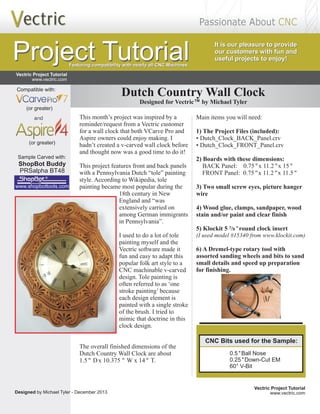
1. Dutch Country Wall Clock
This month’s project was inspired by a
reminder/request from a Vectric customer
for a wall clock that both VCarve Pro and
Aspire owners could enjoy making. I
hadn’t created a v-carved wall clock before
and thought now was a good time to do it!
This project features front and back panels
with a Dutch “tole” painting
style.
I used to do a lot of tole
painting myself and the
Vectric software made it
fun and easy to adapt this
popular folk art style to a
CNC machinable v-carved
design.
I tried to
mimic that doctrine in this
clock design.
Pennsylvania
According to Wikipedia, tole
painting became most popular during the
18th century in New
England and “was
extensively carried on
among German immigrants
in Pennsylvania”.
Tole painting is
often referred to as ‘one
stroke painting’ because
each design element is
painted with a single stroke
of the brush.
The overall finished dimensions of the
Dutch Country Wall Clock are about
1.5" Dx 10.375 " W x 14" T.
Vectric Project Tutorial
Main items you will need:
1) The Project Files (included):
• Dutch_Clock_BACK_Panel.crv
• Dutch_Clock_FRONT_Panel.crv
"
2) Boards with these dimensions:
BACK Panel: 0.75"x 11.2 x 15"
FRONT Panel: 0.75"x 11.2"x 11.5"
3) Two small screw eyes, picture hanger
wire
4) Wood glue, clamps, sandpaper, wood
stain and/or paint and clear finish
7
5) Klockit 5 /8 "round clock insert
(I used model #15340 from www.klockit.com)
6) A Dremel-type rotary tool with
assorted sanding wheels and bits to sand
small details and speed up preparation
for finishing.
Designed for Vectric™ by Michael Tyler
Designed by Michael Tyler - December 2013 www.vectric.com
Vectric Project Tutorial
www.vectric.com
Project Tutorial
Project Tutorial It is our pleasure to provide
our customers with fun and
useful projects to enjoy!
It is our pleasure to provide
our customers with fun and
useful projects to enjoy!
Featuring compatibility with nearly all CNC Machines
CNC Bits used for the Sample:
0.5 "Ball Nose
"
0° V-Bit
0.25 Down-Cut EM
6
Sample Carved with:
ShopBot Buddy
www.shopbottools.com
®
PRSalpha BT48
and
(or greater)
Compatible with:
(or greater)
2. STEP 1 - Open and Review the Project Files
Start your or Aspire software and open the
project files. (fig. 1)
Dimensions for the clock insert cutout is based upon
the one purchased for the sample. Be sure to measure
your own clock insert to make certain the cutout is
suitably sized. If necessary, you can easily adjust the
circle cutout dimension(s) to fit your particular clock
insert. (Recalculate the toolpaths if any changes are
made!)
VCarve Pro
Carefully review all the toolpaths and make any
necessary changes to suit your particular bits and
machine. The toolpaths are currently set with feeds,
speeds and pass depths that were used in creating the
original sample. Please don’t use them directly until
you review them for your own setup.
(cont.)
Page 2
(cont.)
You can edit the tools and change the settings to your
own preferences and requirements. It is VERY
IMPORTANT to recalculate all toolpaths after
making any edits/changes. Once you have
recalculated for your own machine and bits, reset the
preview, then preview all toolpaths again to visually
verify the project outcome on-screen. The project is
designed with tabs to hold parts in place during the
final part cut outs. You may delete the tabs if you use
some other reliable hold-down method.
STEP 2 - Run the Project
When you are satisfied with your settings, save the
toolpaths to the appropriate Post Processor for your
machine, place your material on your machine bed and
proceed to run the project files. (fig. 2a, 2b, 2c)
Vectric Project Tutorial
www.vectric.com
fig. 1
fig. 2a
fig. 2c
Dutch Country Wall Clock
Dutch_Clock_BACK_Panel.crv
Dutch_Clock_FRONT_Panel.crv
fig. 2b
3. STEP 2 - Run the Project (cont.)
Your boards will look something like this: (fig. 2d, 2e)
STEP 3 - Release and Sand Parts
Separate all the parts from the boards with a utility
knife or small saw and sand off the tab remnants.
(fig. 3a)
Page 3
Glue the front and back panels together and clamp until
dry. (fig. 3b, 3c)
When dry, remove the clamps. Sand the edges to blend,
then sand overall to remove any undesirable tool marks
and prepare for finishing. Sand by hand or use a power
sander to make the job go faster. (fig. 3d)
(cont.)
(cont.)
Vectric Project Tutorial
www.vectric.com
fig. 3a
fig. 3c
A spindle sander is great
for sanding curved edges
fig. 3b
Dutch Country Wall Clock
Dutch_Clock_BACK_Panel.crv
Dutch_Clock_FRONT_Panel.crv
fig. 3d
fig. 2d
fig. 2e
4. Page 4
Vectric Project Tutorial
www.vectric.com
STEP 4 - Finish Application
Apply the finish of your choice. Here’s what I used on
the sample Dutch Country Clock made from Select
Pine:
(fig. 4a, 4b, 4c)
• Two light coats Zinnser Bulls Eye spray Shellac,
sanding between coats (slightly sealing the wood)
• Rust-Oleum Ultimate stain - American Walnut
(brushed on, wiped off, blew out excess stain from the
crevices with compressed air, then “stippled” the
stained surface and dry-brushed to even out the color)
• Several coats Zinnser Bulls Eye spray Shellac for
final topcoat
STEP 5 - Install Hanger and Clock Insert
After the finish is dry, insert the 2 screw eyes into the
top area of the center cavity on the back. Twist/fasten a
short length of picture wire to the screw eyes. (fig. 5a)
Push the clock insert into the front center hole - it’s a
friction fit. (fig. 5b)
IN CONCLUSION
I hope you enjoyed your Dutch Country Clock Project!
Happy Carving!
(cont.)
fig. 4b
Brushing on
the Stain
Spray Shellac
Clear Coat
Dutch Country Wall Clock
fig. 5a
fig. 5b
“Stippling” and
dry-brushing
the Stain
fig. 4a
fig. 4c
fig. 4b
5. Page 5
Materials Source Page
Vectric Project Tutorial
www.vectric.com
• 3M Radial Bristle Discs from
(stack 3 discs at a time on your rotary tool mandrel)
80-grit: part # 4494A19
220-grit: part # 4494A18
www.mcmaster.com
Miscellaneous Items Purchased at Lowes™
• Sandpaper
• Rust-Oleum Ultimate American Walnut Wood Stain
• Disposable Brushes and Paint Rags
• Zinsser Bullseye Spray Shellac (100% wax-free)
• Small Screw Eyes and Picture Hanger Wire
Miscellaneous Items Purchased at Home Depot™
• I used model #15340, but there are several styles to choose from
Clock Insert Purchased Online from www.Klockit.com
6. Page 6
Vectric Project Tutorial
www.vectric.com
The trademarks, service marks and logos used and displayed in this document are registered and unregistered Trademarks of Vectric and others.
Additional Resources
RESOURCES...
There are numerous resources for Vectric software owners to make their experience with their products more
enjoyable. The Vectric website includes video tutorials and more, to provide a good overview of the software
products and how to use them. Please visit the Support page for a complete listing of available resources for you.
Vectric Support: http://support.vectric.com/
Vectric User Forum
Every owner should join the Vectric User Forum (http://www.vectric.com/forum/) where fellow users share their
experience and knowledge on a daily basis. It is a FREE service that you will surely appreciate. A handy Search
Feature helps you find answers to any questions you may have. There are Gallery sections as well, where you can
post and view photos of projects created with Vectric software.
IMPORTANT: Before outputting any toolpaths you should carefully check all part sizes and the material setup to
make sure they are appropriate for your actual setup.You should also check and re-calculate all toolpaths with safe
and appropriate settings for your material, CNC machine and tooling.
Terms of Use: This Project and artwork is provided on the understanding that it will only be used with Vectric
software programs. You may use the designs to carve parts for sale but the Files and/or Vectors, Components or
Toolpaths within them (or any derivatives) may not be converted to other formats, sold to, or shared with anyone
else. This project is Copyright 2013 - Vectric Ltd.