Download to read offline
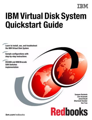


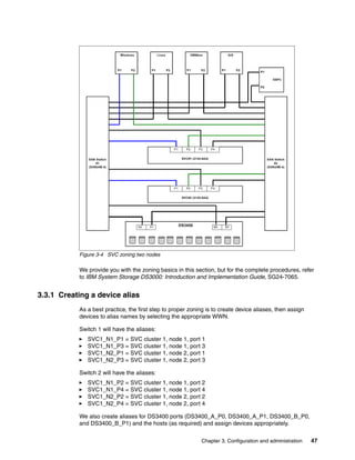
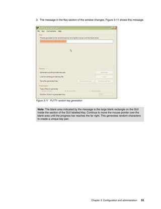

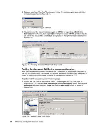
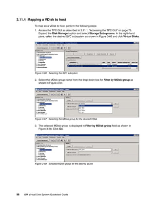
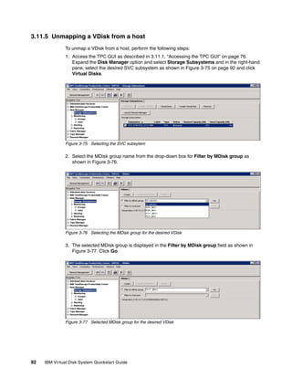

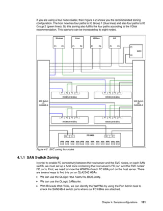
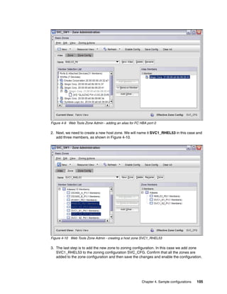
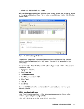
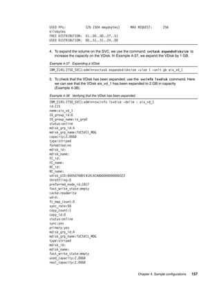
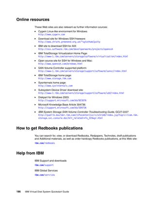
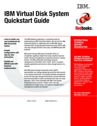
![RHEL 5.3 multipath support
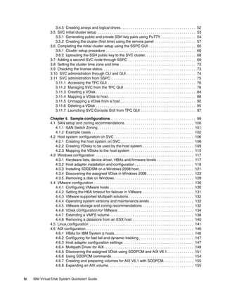
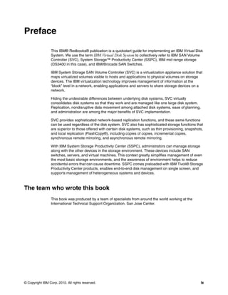
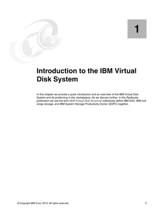
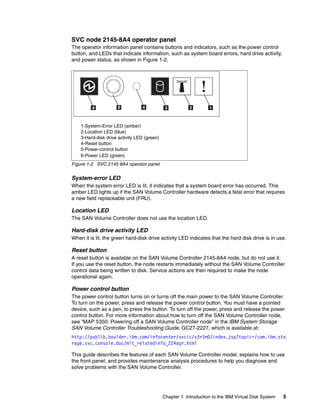
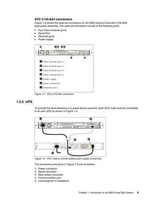
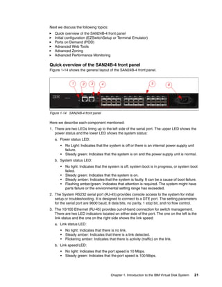
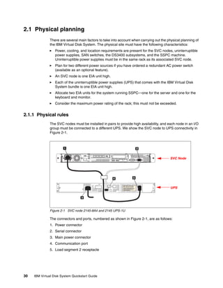
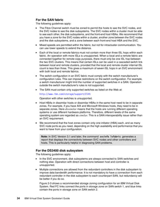
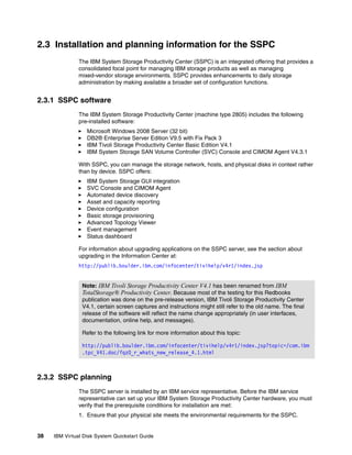
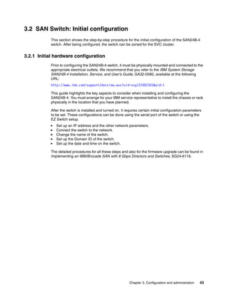
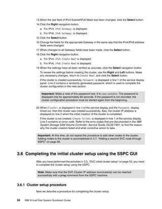
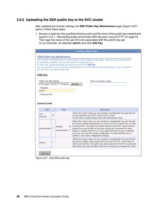
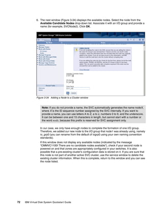
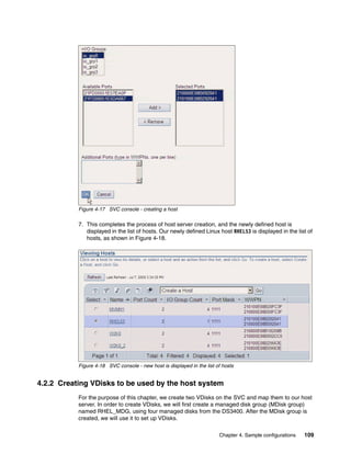
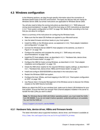
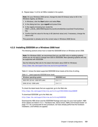
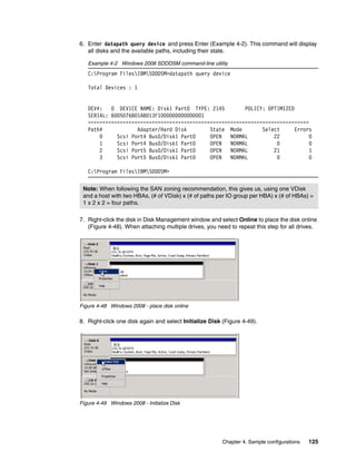
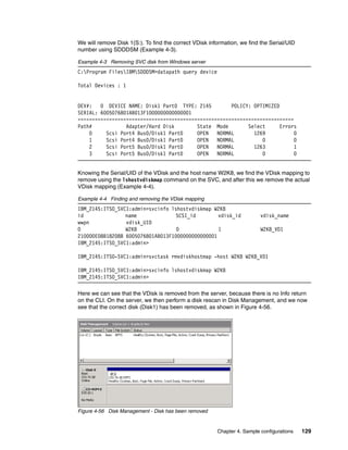
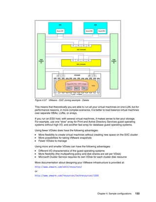
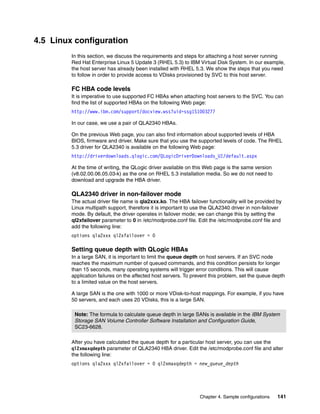
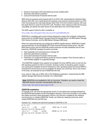
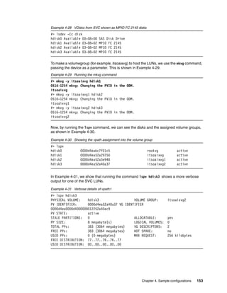
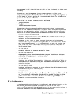
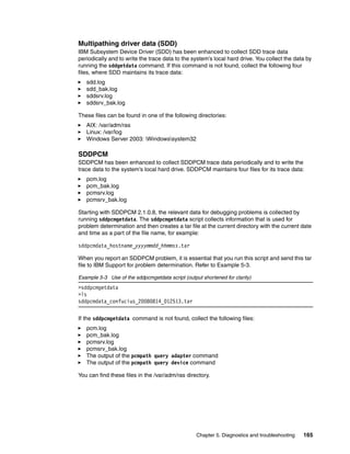
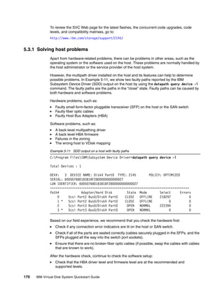
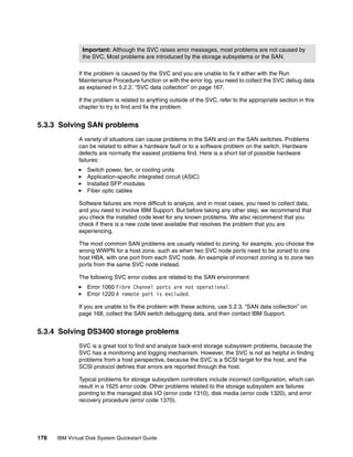
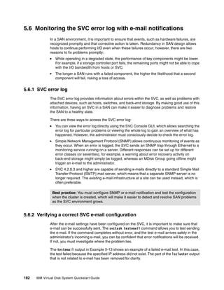
Red Hat Enterprise Linux versions 4 and older supported IBM SDD (Subsystem Device
Driver) multipath solution. RHEL 5 and higher only support native multipathing included in the
operating system: Device Mapper Multipath (DMMP) module. You can verify this on the SVC
recommended software levels Web page:
http://www.ibm.com/support/docview.wss?uid=ssg1S1003278#RedHatLinux
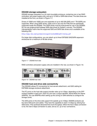
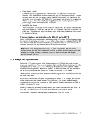
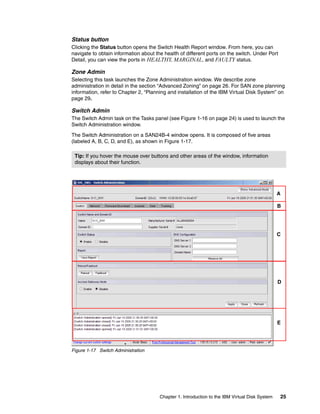
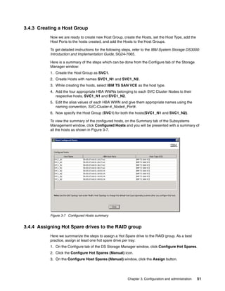
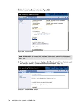
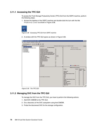
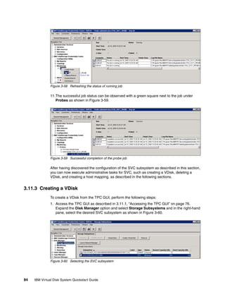
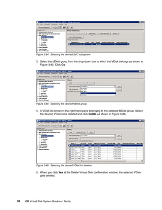
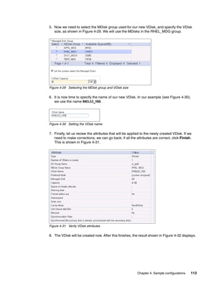
Follow these steps to enable DMMP support for SVC in RHEL 5.3.
1. Make sure the following DMMP packages are installed on the Linux server:
– device-mapper
– device-mapper-multipath
We can verify this result with the command, rpm -qa | grep device-mapper, as shown in
Example 4-10.
Example 4-10 Device-mapper packages
[root@localhost SJ2009]# rpm -qa | grep device-mapper
device-mapper-event-1.02.28-2.el5
device-mapper-1.02.28-2.el5
device-mapper-multipath-0.4.7-23.el5
As you can see, the required device-mapper packages are installed.
2. Edit the /etc/multipath.conf file and make sure that it contains the sections listed in
Example 4-11. You can also download the Device Mapper Multipath Configuration file at:
http://www.ibm.com/support/docview.wss?uid=ssg1S4000107#RSSM
Example 4-11 /etc/multipath.conf sections
defaults {
polling_interval 30
failback immediate
no_path_retry 5
rr_min_io 100
path_checker tur
user_friendly_names yes
}
# SVC
device {
vendor "IBM"
product "2145"
path_grouping_policy group_by_prio
prio_callout "/sbin/mpath_prio_alua /dev/%n"
prio "alua /dev/%a"
}
3. Enable autoload of device-mapper by issuing one of the following commands as root:
chkconfig multipathd on
chkconfig --level 345 multipathd on
4. Manually start DMMP by issuing the following command:
/etc/init.d/multipathd start
142 IBM Virtual Disk System Quickstart Guide](https://image.slidesharecdn.com/ibmvirtualdisksystemquickstartguidesg247794-120524200746-phpapp01/85/Ibm-virtual-disk-system-quickstart-guide-sg247794-156-320.jpg)
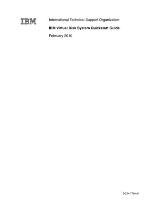
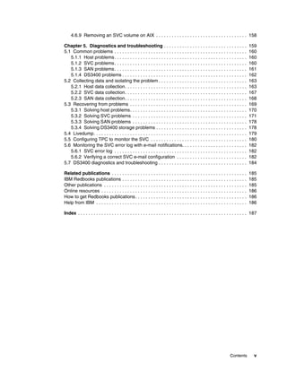
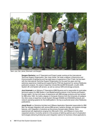
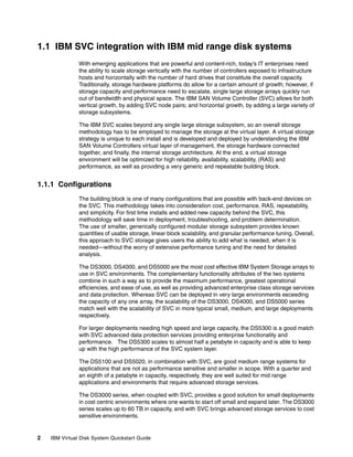
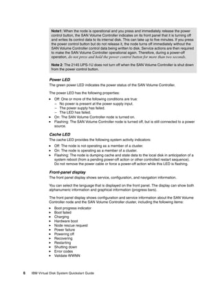
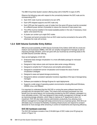
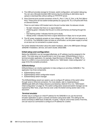
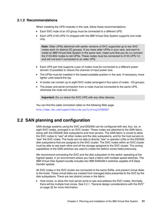
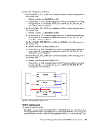
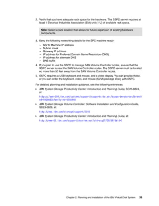
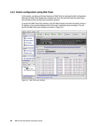
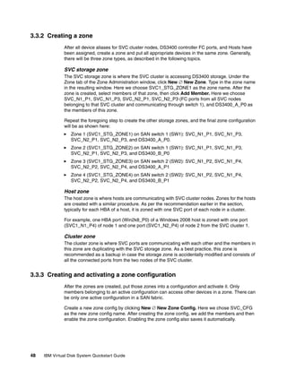
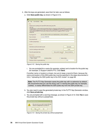
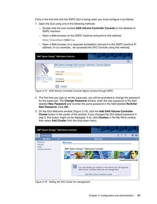
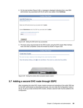
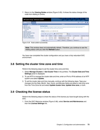
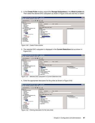
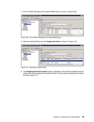
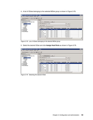
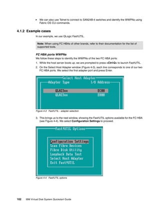
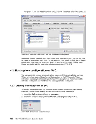
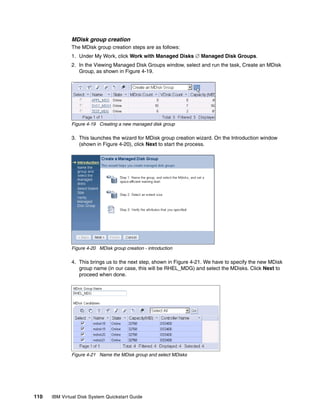
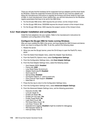
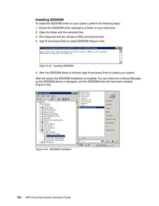
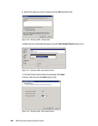
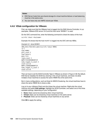
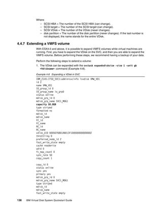
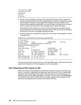
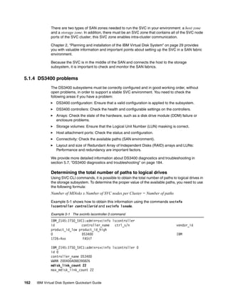
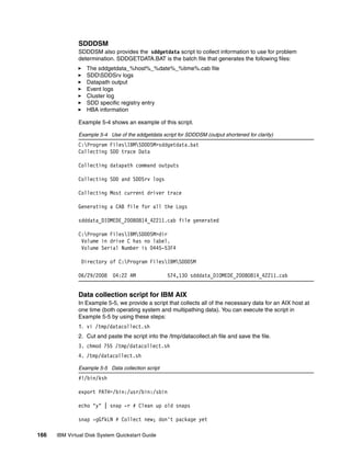
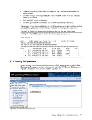
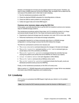
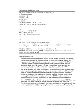
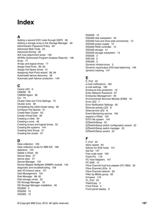
![Discover the VDisk on Linux
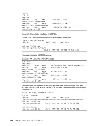
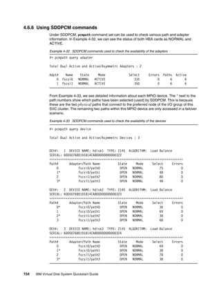
Now we can expect our Linux host server to see the two VDisks mapped to it. If the host does
not see them, perform any of the following actions:
Reboot the host server.
Unload and reload the FC HBA driver.
If none of these actions is possible (for example, due to no downtime allowed), you can run
the following commands on the host:
echo “- - -” > /sys/class/scsi_host/host0/scan
echo “- - -” > /sys/class/scsi_host/host1/scan
We continue the procedure with creating partitions and file systems on the two VDisks.
Creating partitions on assigned disks / vdisks
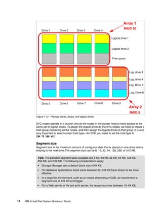
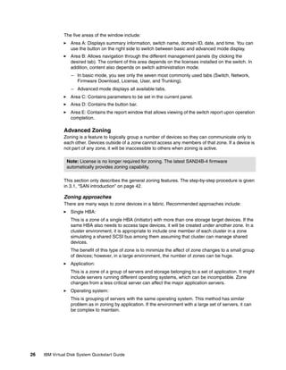
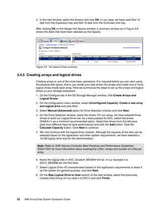
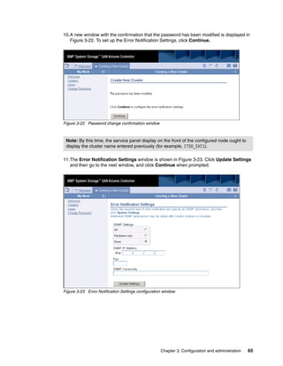
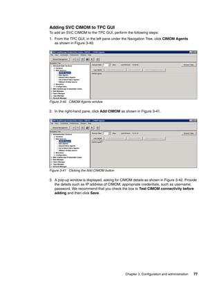
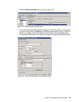
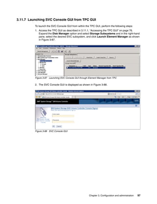
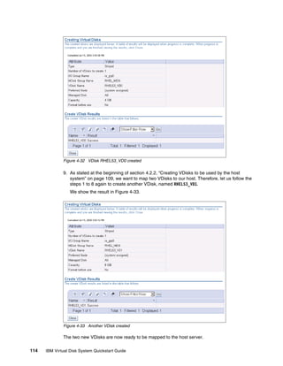
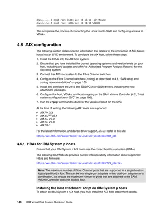
The multipath functionality of device-mapper represents the VDisks mapped to the Linux host
as /dev/dm-0, /dev/dm-1 and so on. To verify that the multipathd service is active, use the
commands listed in Example 4-12.
Example 4-12 Status of multipathd
[root@localhost ~]# service multipathd status
multipathd (pid 2064) is running...
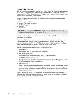
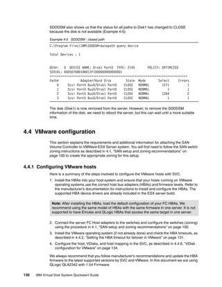
We can now scan and view the multipath devices. Example 4-13 lists the output of two
commands that we use to perform:
multipath -v2
multipath -ll
Example 4-13 Scan and view multipath devices
[root@localhost ~]# multipath -v2
[root@localhost ~]# multipath -ll
mpath1 (36005076801ab013f1000000000000008) dm-1 IBM,2145
[size=8.0G][features=1 queue_if_no_path][hwhandler=0][rw]
_ round-robin 0 [prio=100][active]
_ 0:0:0:1 sdb 8:16 [active][ready]
_ 1:0:0:1 sdf 8:80 [active][ready]
_ round-robin 0 [prio=20][enabled]
_ 0:0:1:1 sdd 8:48 [active][ready]
_ 1:0:1:1 sdh 8:112 [active][ready]
mpath0 (36005076801ab013f1000000000000007) dm-0 IBM,2145
[size=4.0G][features=1 queue_if_no_path][hwhandler=0][rw]
_ round-robin 0 [prio=100][active]
_ 0:0:1:0 sdc 8:32 [active][ready]
_ 1:0:1:0 sdg 8:96 [active][ready]
_ round-robin 0 [prio=20][enabled]
_ 0:0:0:0 sda 8:0 [active][ready]
_ 1:0:0:0 sde 8:64 [active][ready]
The output shows our two VDisks and the FC paths to them. Each VDisk is accessible
through four paths. The two VDisks on our SVC are presented as the following devices:
/dev/mpath/mpath0
/dev/mpath/mpath1
Chapter 4. Sample configurations 143](https://image.slidesharecdn.com/ibmvirtualdisksystemquickstartguidesg247794-120524200746-phpapp01/85/Ibm-virtual-disk-system-quickstart-guide-sg247794-157-320.jpg)
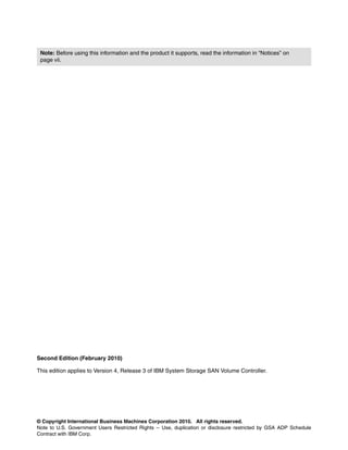
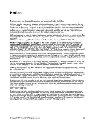
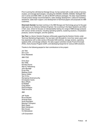
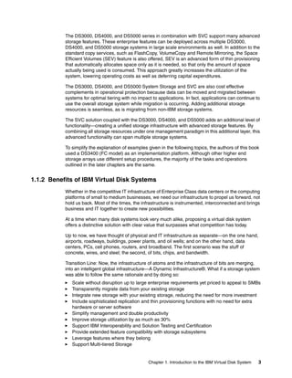
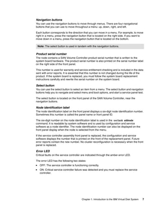
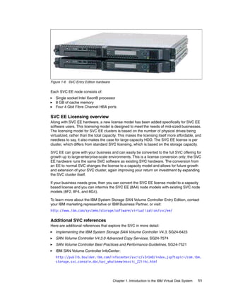
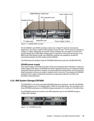
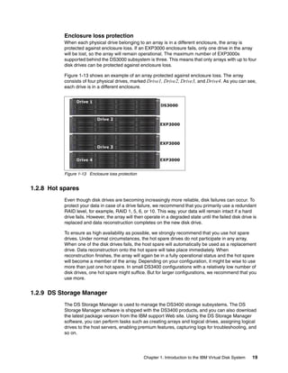
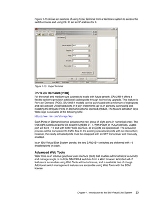
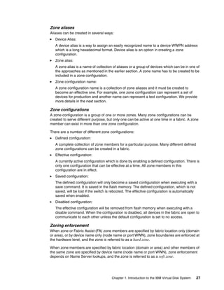
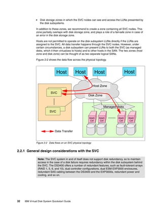
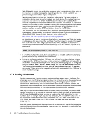
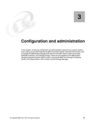
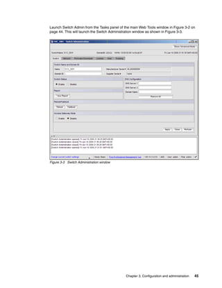
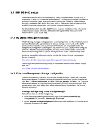
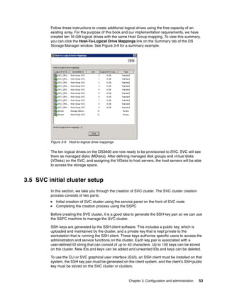
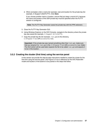
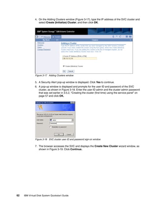
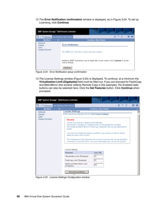
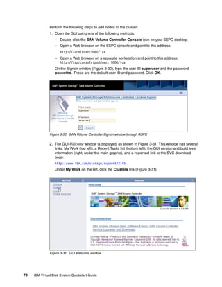
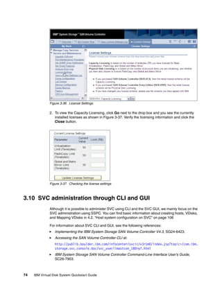
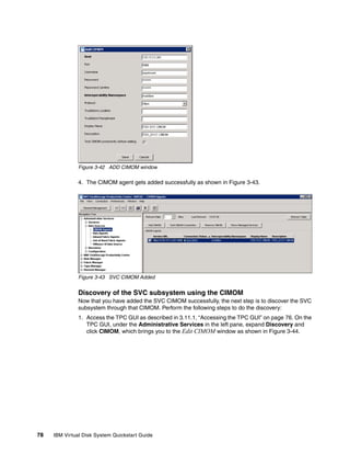
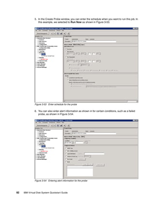
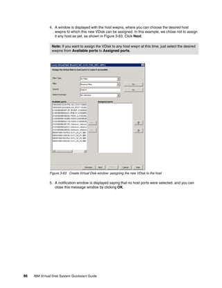
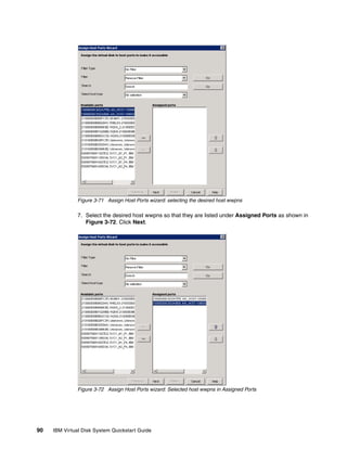
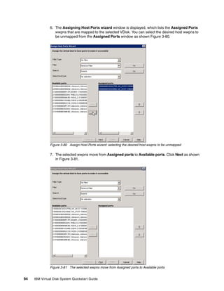
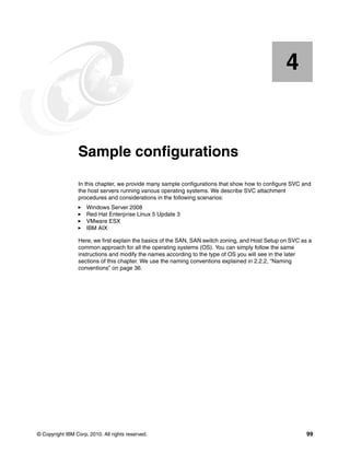
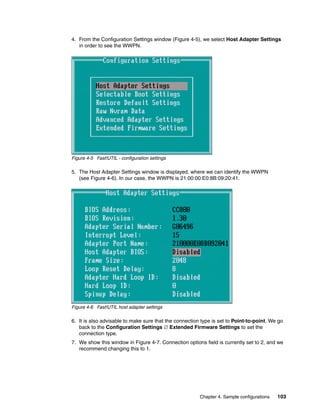
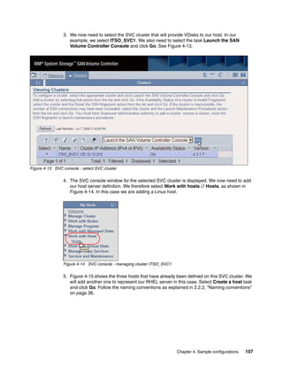
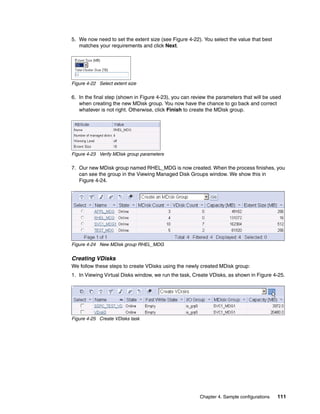
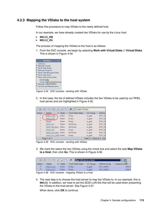
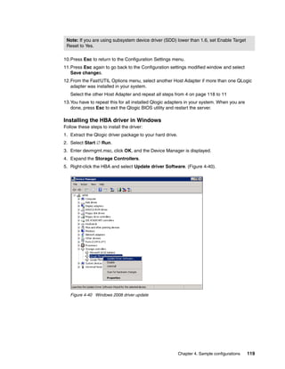
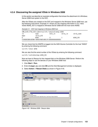
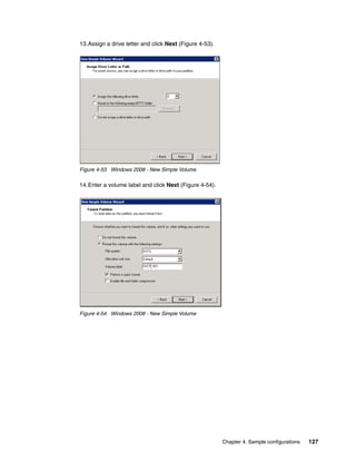
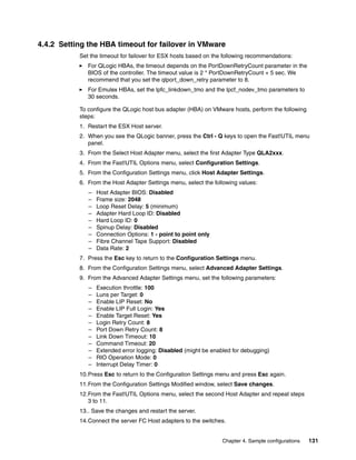
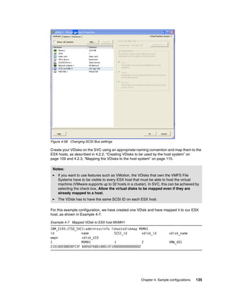
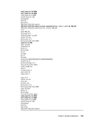
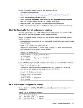
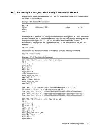
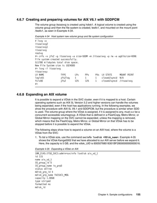
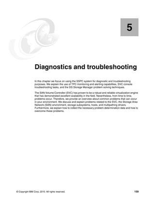
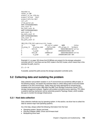
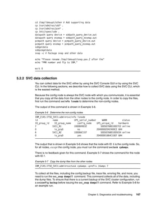
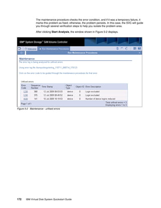
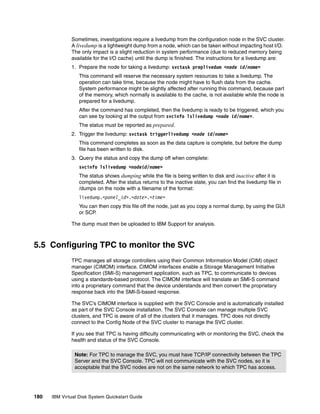
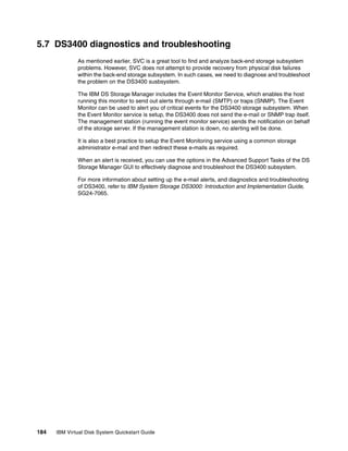
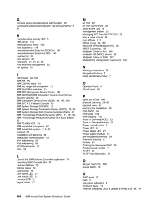
![However, to create partitions, we need to use the fdisk command on the underlying disks
/dev/dm-0 and /dev/dm-1. Run fdisk as follows:
fdisk /dev/dm-0
fdisk /dev/dm-1
When done, we can verify the setup of partitions using the fdisk -l command (see
Example 4-14).
Example 4-14 Partitions on VDisks
[root@localhost ~]# fdisk -l
Disk /dev/dm-0: 4294 MB, 4294967296 bytes
255 heads, 63 sectors/track, 522 cylinders
Units = cylinders of 16065 * 512 = 8225280 bytes
Device Boot Start End Blocks Id System
/dev/dm-0p1 1 522 4192933+ 83 Linux
Disk /dev/dm-1: 8589 MB, 8589934592 bytes
255 heads, 63 sectors/track, 1044 cylinders
Units = cylinders of 16065 * 512 = 8225280 bytes
Device Boot Start End Blocks Id System
/dev/dm-1p1 1 1044 8385898+ 83 Linux
Note: The fdisk -l command produces much longer output. In Example 4-14, we only
show the parts relevant to /dev/dm-0 and /dev/dm-1.
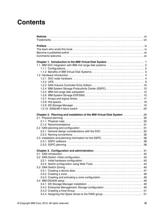
Creating file systems
After the partitions are created, the next step is to create a file system in each partition. In our
example, we have created one partition on each VDisk. We will now create EXT2 file system
on each partition.
We can use the mkfs command, as shown in Example 4-15. The partition on VDisk 0 is
represented as /dev/mpath/mpath0p1, and the partition on VDisk 1 is shown as
/dev/mpath/mpath1p1.
Example 4-15 Creating EXT2 file system in partitions on VDisk 0 and VDisk 1
### Creating file system on VDisk 0 ###
[root@localhost ~]# mkfs -t ext2 /dev/mpath/mpath0p1
mke2fs 1.39 (29-May-2006)
Filesystem label=
OS type: Linux
Block size=4096 (log=2)
Fragment size=4096 (log=2)
524288 inodes, 1048233 blocks
52411 blocks (5.00%) reserved for the super user
First data block=0
Maximum filesystem blocks=1073741824
32 block groups
32768 blocks per group, 32768 fragments per group
16384 inodes per group
144 IBM Virtual Disk System Quickstart Guide](https://image.slidesharecdn.com/ibmvirtualdisksystemquickstartguidesg247794-120524200746-phpapp01/85/Ibm-virtual-disk-system-quickstart-guide-sg247794-158-320.jpg)
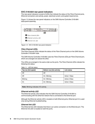
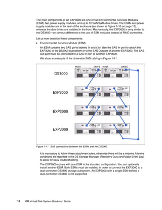
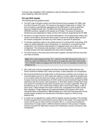
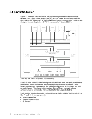
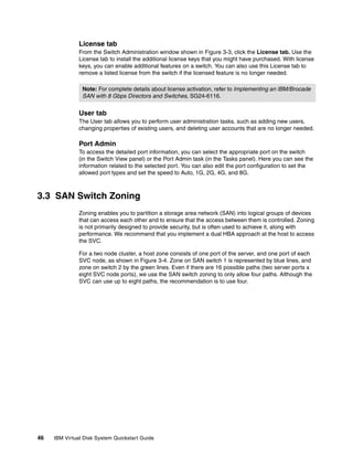
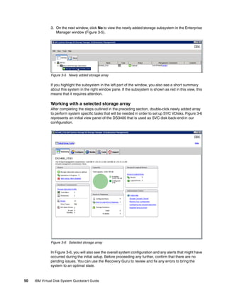
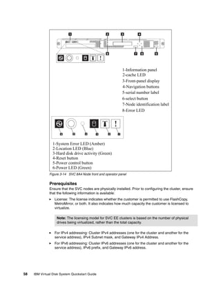
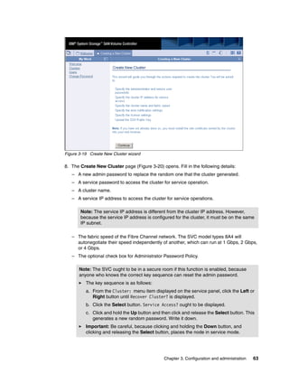
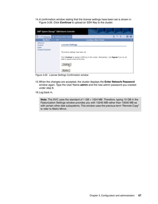
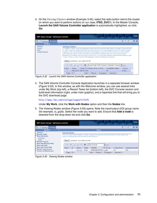
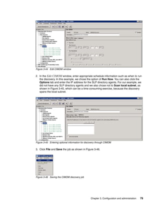
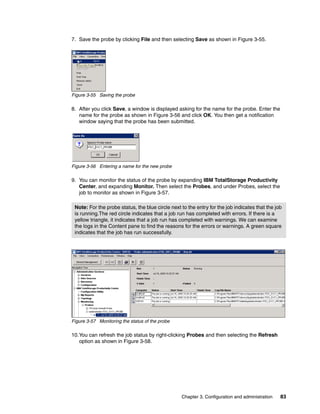
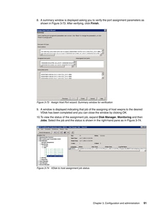
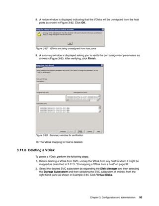
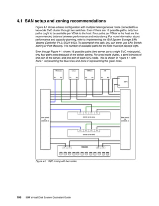
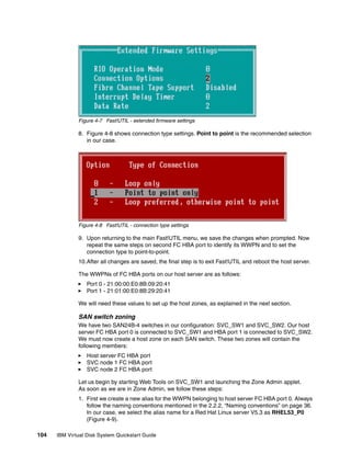
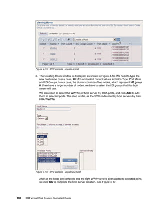
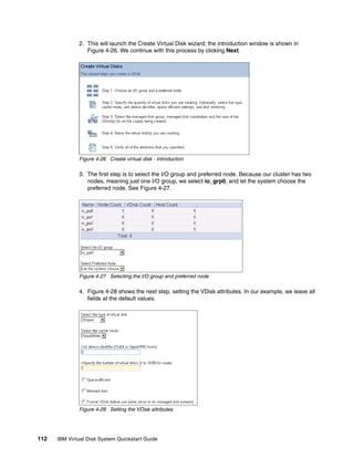
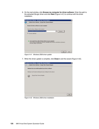
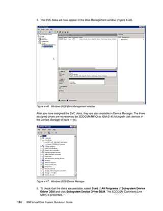
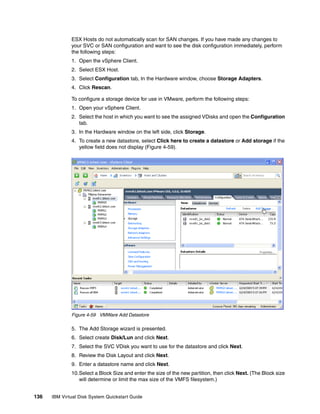
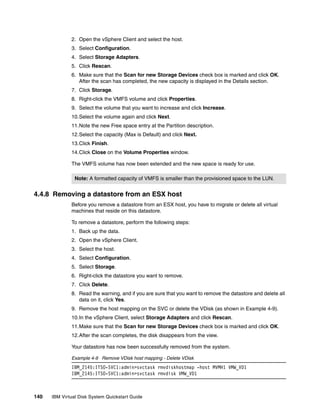
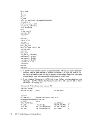
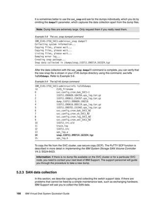
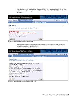
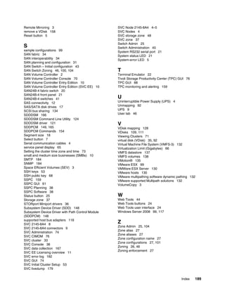
![Superblock backups stored on blocks:
32768, 98304, 163840, 229376, 294912, 819200, 884736
Writing inode tables: done
Writing superblocks and filesystem accounting information: done
This filesystem will be automatically checked every 28 mounts or
180 days, whichever comes first. Use tune2fs -c or -i to override.
### Creating file system on VDisk 1 ###
[root@localhost ~]# mkfs -t ext2 /dev/mpath/mpath1p1
mke2fs 1.39 (29-May-2006)
Filesystem label=
OS type: Linux
Block size=4096 (log=2)
Fragment size=4096 (log=2)
1048576 inodes, 2096474 blocks
104823 blocks (5.00%) reserved for the super user
First data block=0
Maximum filesystem blocks=2147483648
64 block groups
32768 blocks per group, 32768 fragments per group
16384 inodes per group
Superblock backups stored on blocks:
32768, 98304, 163840, 229376, 294912, 819200, 884736, 1605632
Writing inode tables: done
Writing superblocks and filesystem accounting information: done
This filesystem will be automatically checked every 30 mounts or
180 days, whichever comes first. Use tune2fs -c or -i to override.
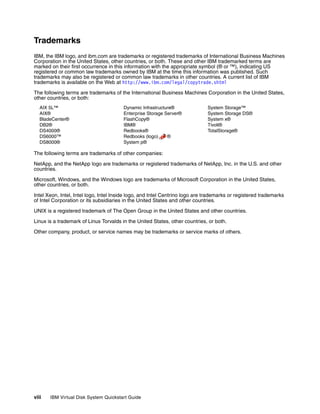
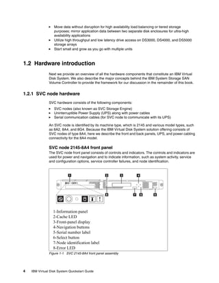
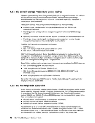
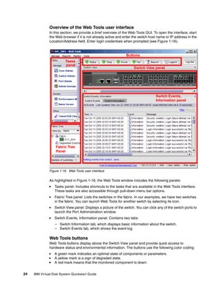
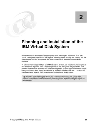
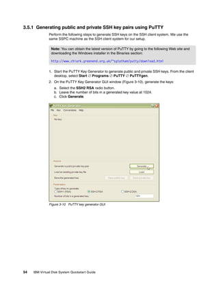
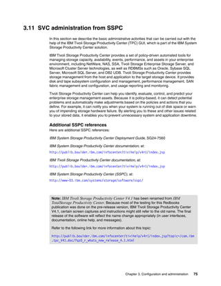
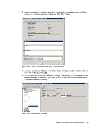
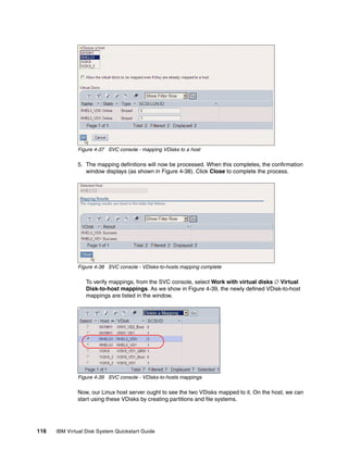
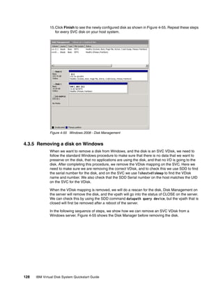
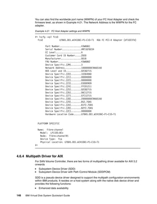
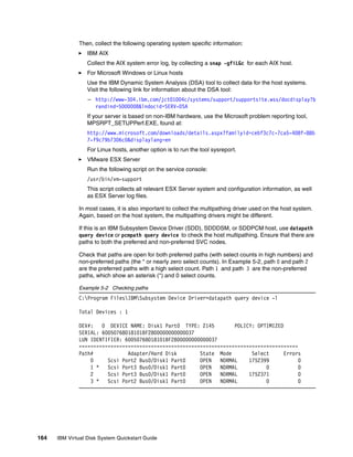
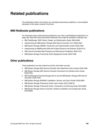
One last step remains: We need to mount the file system on each VDisk with the following set
of commands:
Example 4-16 Creating mount points for VDisks 0 and 1
[root@localhost ~]# mkdir /mnt/VDisk0
[root@localhost ~]# mkdir /mnt/VDisk1
[root@localhost ~]# mount /dev/mpath/mpath0p1 /mnt/VDisk0
[root@localhost ~]# mount /dev/mpath/mpath0p1 /mnt/VDisk1
The two VDisks are now ready for use and accessible through the following mount points:
/mnt/VDisk0
/mnt/VDisk1
For a simple test, we copied a directory named SJ2009 onto VDisk 1. The result is shown in
Example 4-17.
Example 4-17 A directory copied to VDisk 1
[root@localhost ~]# ls /mnt/VDisk1 -al
total 32
drwxr-xr-x 4 root root 4096 Jul 8 15:46 .
drwxr-xr-x 4 root root 4096 Jul 8 13:13 ..
Chapter 4. Sample configurations 145](https://image.slidesharecdn.com/ibmvirtualdisksystemquickstartguidesg247794-120524200746-phpapp01/85/Ibm-virtual-disk-system-quickstart-guide-sg247794-159-320.jpg)
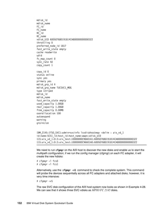
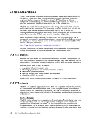
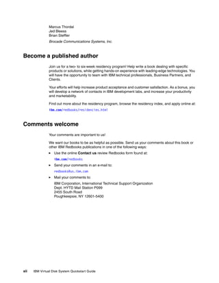
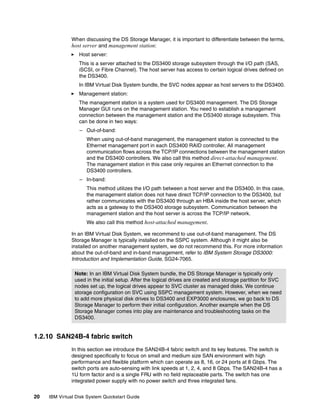
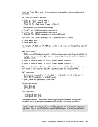
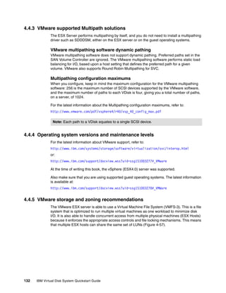
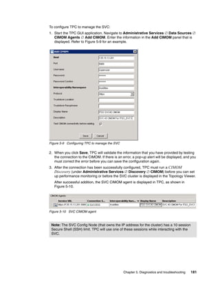
![IBM System Storage/Brocade SAN switches
For most of the current Brocade switches, you need to issue the supportSave command to
collect the support data.
Example 5-10 shows the use of supportSave command (in interactive mode) on an IBM
System Storage SAN24B-4 SAN switch.
Example 5-10 The supportSave output from IBM SAN24B-4 switch (output shortened for clarity)
SVC_SW1:admin> supportSave
This command will collect RASLOG, TRACE, supportShow, core file, FFDC data
and other support information from both active and standby CPs and then transfer
them to a FTP/SCP server
or a USB device.This operation can take several minutes.
NOTE: supportSave will transfer existing trace dump file first, then
automatically generate and transfer latest one. There will be two trace dump
files transfered after this command.
OK to proceed? (yes, y, no, n): [no] y
Host IP or Host Name: 135.15.13.241
User Name: IBMuser
Password:
Protocol (ftp or scp): ftp
Remote Directory: /
Saving support information for chassis:Brocade300, module:RAS...
........
Saving support information for chassis:Brocade300, module:TRACE_OLD...
Saving support information for chassis:Brocade300, module:TRACE_NEW...
Saving support information for chassis:Brocade300, module:FABRIC...
....
....
....
Saving support information for chassis:Brocade300, module:MAPS...
Saving support information for chassis:Brocade300, module:RAS_POST...
......
SupportSave completed
5.3 Recovering from problems
In this section, we provide guidance about how to recover from several of the more common
problems that you might encounter. We also show example problems and how to fix them. In
all cases, it is essential to read and understand the current product limitations to verify the
configuration and to determine if you need to upgrade any components or to install the latest
fixes or patches.
To obtain support for IBM products, visit the IBM Support Web page on the Internet:
http://www.ibm.com/support/us/en/
From this IBM Support Web page, you can obtain various types of support by following the
links that are provided on this page.
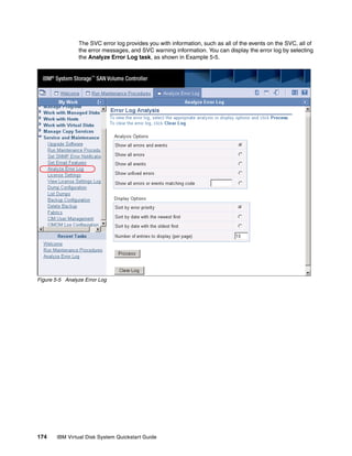
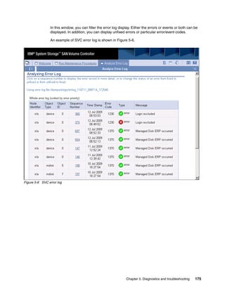
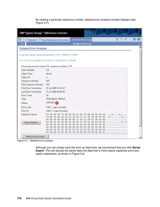
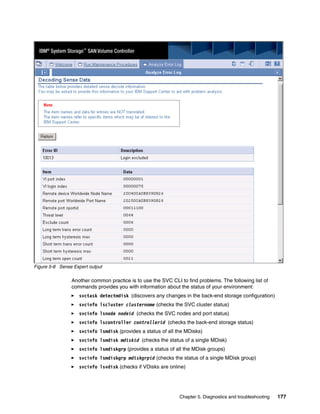
Chapter 5. Diagnostics and troubleshooting 169](https://image.slidesharecdn.com/ibmvirtualdisksystemquickstartguidesg247794-120524200746-phpapp01/85/Ibm-virtual-disk-system-quickstart-guide-sg247794-183-320.jpg)


This document provides a quickstart guide for installing and configuring the IBM Virtual Disk System, which integrates the IBM SAN Volume Controller (SVC) with IBM midrange disk systems. It includes an introduction to the hardware components, such as the SVC node, UPS, IBM System Storage Productivity Center, DS3400 storage subsystem, EXP3000 expansion unit, and Brocade SAN switches. It also covers planning the physical layout and SAN configuration, installing and setting up the SVC cluster, DS3400, zoning the SAN switch, and creating virtual disks on the SVC. Sample configurations are presented to demonstrate typical implementations.


![5G Explained! A High Level Overview [Introduction]](https://cdn.slidesharecdn.com/ss_thumbnails/5gexplainedahighleveloverview-260119165306-cc137a3e-thumbnail.jpg?width=640&height=640&fit=bounds)


