Accelerometer
• An accelerometeris an electromechanical device that measures
acceleration forces.
• These forces may be static, like the constant force of gravity pulling at
your feet, or they could be dynamic - caused by moving or vibrating
the accelerometer.
3.
Accelerometer
• There aretwo types of acceleration forces: static forces and dynamic forces.
• Static forces are forces that are constantly being applied to the object (such as friction
or gravity).
• Dynamic forces are “moving” forces applied to the object at various rates (such
as vibration, or the force exerted on a cue ball in a game of pool). This is why
accelerometers are used in automobile collision safety systems.
• For example. When a car is acted on by a powerful dynamic force, the accelerometer
(sensing a rapid deceleration) sends an electronic signal to an embedded computer,
which in turn deploys the airbags.
4.
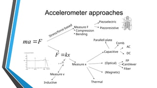
Accelerometer approaches
F
ma
MeasureF
• Compression
• Bending
Stress/force based
kx
F
Piezoelectric
Piezoresistive
Measure x
Capacitive
(Optical)
(Magnetic)
AC
DC
FP
Thermal
Parallell plate
Comb
Measure v
Inductive
Cantilever
Fiber
dt
dx
v
5.
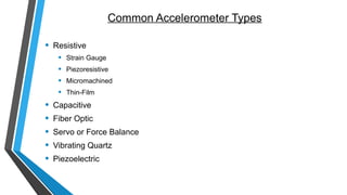
Common Accelerometer Types
•Resistive
• Strain Gauge
• Piezoresistive
• Micromachined
• Thin-Film
• Capacitive
• Fiber Optic
• Servo or Force Balance
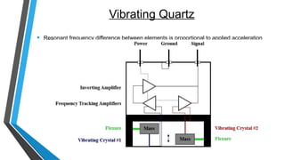
• Vibrating Quartz
• Piezoelectric
6.
What are accelerometersuseful for?
• By measuring the amount of static acceleration due to gravity, we can
find out the angle the device is tilted at with respect to the earth.
• By sensing the amount of dynamic acceleration, we can analyze the
way the device is moving.
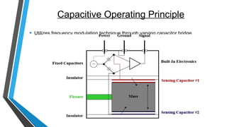
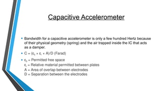
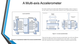
Capacitive Accelerometer
• Bandwidthfor a capacitive accelerometer is only a few hundred Hertz because
of their physical geometry (spring) and the air trapped inside the IC that acts
as a damper.
• C = (ε0 × εr × A)/D (Farad)
• ε0 = Permitted free space
εr = Relative material permitted between plates
A = Area of overlap between electrodes
D = Separation between the electrodes
11.
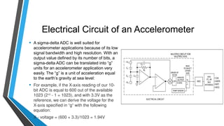
Electrical Circuit ofan Accelerometer
• A sigma-delta ADC is well suited for
accelerometer applications because of its low
signal bandwidth and high resolution. With an
output value defined by its number of bits, a
sigma-delta ADC can be translated into “g”
units for an accelerometer application very
easily. The “g” is a unit of acceleration equal
to the earth’s gravity at sea level:
• For example, if the X-axis reading of our 10-
bit ADC is equal to 600 out of the available
1023 (210
- 1 = 1023), and with 3.3V as the
reference, we can derive the voltage for the
X-axis specified in “g“ with the following
equation:
• X - voltage = (600 × 3.3)/1023 = 1.94V
12.
Electrical Circuit ofan Accelerometer
• Each accelerometer has a zero-g voltage level that is the voltage that
corresponds to 0g. We first calculate the voltage shifts from zero-g
voltage (specified in the data sheet and assumed to be 1.65V) as:
• 1.94V - 1.65V = 0.29V
• Now, to do the final conversion we divide 0.29V by the accelerometer’s
sensitivity (specified in the data sheet and assumed to be 0.475V/g):
• 0.29V/0.475V/g = 0.6g
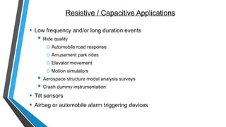
Resistive / CapacitiveApplications
• Low frequency and/or long duration events
Ride quality
o Automobile road response
o Amusement park rides
o Elevator movement
o Motion simulators
Aerospace structure modal analysis surveys
Crash dummy instrumentation
• Tilt sensors
• Airbag or automobile alarm triggering devices
16.
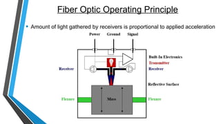
Fiber Optic OperatingPrinciple
• Amount of light gathered by receivers is proportional to applied acceleration
17.
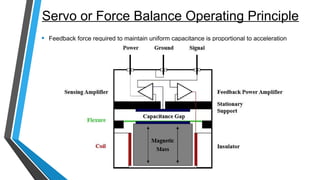
Servo or ForceBalance Operating Principle
• Feedback force required to maintain uniform capacitance is proportional to acceleration
Piezoelectric Accelerometer
• Piezoelectricaccelerometer is based on principle of piezoelectric
effect.
• A Piezoelectric substance is one that produces an electric charge
when a mechanical stress is applied.
• In a Piezoelectric accelerometer a mass is attached to a Piezoelectric
crystal which is in turn mounted to the case of the accelerometer.
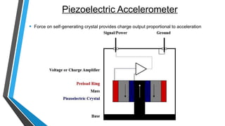
Piezoelectric Accelerometer
• Whenthe body of the accelerometer is subjected to vibration the mass
mounted on the crystal wants to stay still in space due to inertia and so
compresses and stretches the piezo electric crystal.
• This force causes a charge to be generated and due to Newton law
(F=ma) this force is in turn proportional to acceleration.
• The charge output is converted to voltage output by the use of integral
electronics (for example: in an IEPE accelerometer) or made available
as a charge output (pc /g) in a charge output Piezo electric
accelerometer.
22.
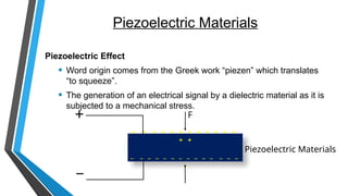
Piezoelectric Materials
Piezoelectric Effect
•Word origin comes from the Greek work “piezen” which translates
“to squeeze”.
• The generation of an electrical signal by a dielectric material as it is
subjected to a mechanical stress.
+ + + + + + + + + + + +
+ +
_ _ _ _ _ _ _ _ _ _ _ _ _ _
_
+
_
F
Piezoelectric Materials
23.
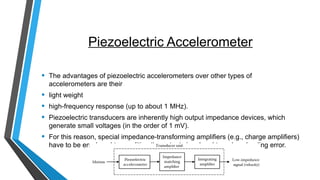
Piezoelectric Accelerometer
• Theadvantages of piezoelectric accelerometers over other types of
accelerometers are their
• light weight
• high-frequency response (up to about 1 MHz).
• Piezoelectric transducers are inherently high output impedance devices, which
generate small voltages (in the order of 1 mV).
• For this reason, special impedance-transforming amplifiers (e.g., charge amplifiers)
have to be employed to condition the output signal and to reduce loading error.
24.
Piezoelectric Materials
• NaturallyPiezoelectric
• Rochelle Salt (Potassium
sodium tartrate tetrahydrate)
• One of first materials used to
make sensors
• Tourmaline
• Sensitive to hydrostatic pressure
• Exotic, “Man-Made” Materials
• Langasite
• Lithium Niobate
• Cultured Quartz
• Artificially Polarized
• Piezofilm
• Made of a special polymer -
PVDF
• Piezoceramics
• Lead Zirconate Titanate (PZT)
• Bismuth Titanate
25.
Mechanical Design
• PiezoelectricSensing Element
• Mechanical transduction mechanism as important as piezoelectric material
selection
• The key is to design the sensor so that it only measures the parameter of
interest and minimizes the affects of any outside environmental conditions
• Types
• Compression Mode
• Flexural Mode
• Shear Mode
26.
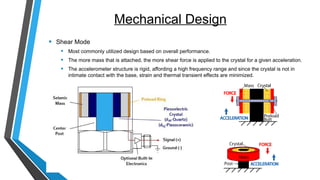
Mechanical Design
• ShearMode
• Most commonly utilized design based on overall performance.
• The more mass that is attached, the more shear force is applied to the crystal for a given acceleration.
• The accelerometer structure is rigid, affording a high frequency range and since the crystal is not in
intimate contact with the base, strain and thermal transient effects are minimized.
27.
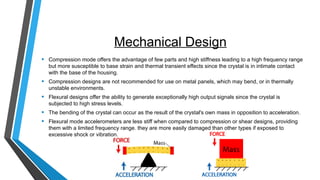
Mechanical Design
• Compressionmode offers the advantage of few parts and high stiffness leading to a high frequency range
but more susceptible to base strain and thermal transient effects since the crystal is in intimate contact
with the base of the housing.
• Compression designs are not recommended for use on metal panels, which may bend, or in thermally
unstable environments.
• Flexural designs offer the ability to generate exceptionally high output signals since the crystal is
subjected to high stress levels.
• The bending of the crystal can occur as the result of the crystal's own mass in opposition to acceleration.
• Flexural mode accelerometers are less stiff when compared to compression or shear designs, providing
them with a limited frequency range. they are more easily damaged than other types if exposed to
excessive shock or vibration.
28.
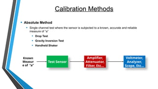
Calibration Methods
• AbsoluteMethod
• Single channel test where the sensor is subjected to a known, accurate and reliable
measure of “a”
• Drop Test
• Gravity Inversion Test
• Handheld Shaker
Known
Measur
e of “a”
Test Sensor
Amplifier,
Attenuator,
Filter, Etc...
Voltmeter,
Analyzer,
Scope, Etc...
29.
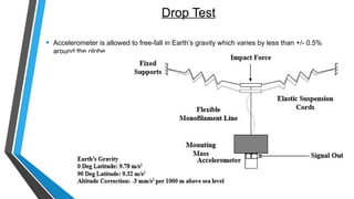
Drop Test
• Accelerometeris allowed to free-fall in Earth’s gravity which varies by less than +/- 0.5%
around the globe
30.
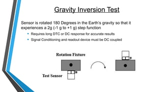
Gravity Inversion Test
Sensoris rotated 180 Degrees in the Earth’s gravity so that it
experiences a 2g (-1 g to +1 g) step function
• Requires long DTC or DC response for accurate results
• Signal Conditioning and readout device must be DC coupled
31.
Applications of Accelerometers
•Used in cars to study shock and vibrations.
• Camcorders use accelerometers for image stabilization.
• Still cameras use accelerometers for anti-blur capturing.
• Used in mobile phones for multiple functions including tilt detection, motion detection..etc.
• Process control systems and safety installations in industries.
• Used to measure seismic activity, inclination, machine vibration, dynamic distance and
speed with or without the influence of gravity.
32.
Applications of Accelerometers
•Most accelerometers are miniscule, and they are often referred to as Micro-
Electro-Mechanical Systems (MEMS) accelerometers. Because of their size and
affordability, they are embedded in a myriad of hand-held electronic devices
(such as phones, tablets, and video game controllers).
• In phones and tablets, the accelerometer is responsible for “flipping” the screen
when the device is rotated.
• Accelerometers are also used by zoologists (to track the movement of animals
in the wild), engineers (especially in collision experiments) and factories (to
monitor the vibration of machinery).
33.
MEMS
Micro-Electro-Mechanical-Systems
• The MEMSare very small systems or devices, composed of micro
components ranging from 0.001 mm to 0.1 mm in size.
• These components are made of silicon, polymers, metals and/or
ceramics.
• They are usually combined with a CPU (Microcontroller) for completing
the system.