The document discusses the insulator design of overhead lines, including types, materials, applications, and recent developments in insulator technology. It covers various aspects such as design considerations for insulators, foundations, dampers, and transmission towers, emphasizing the importance of material performance and reliability under specific conditions. Recent trends include the development of hybrid insulators, which combine the benefits of porcelain and polymer materials for enhanced performance in challenging environments.
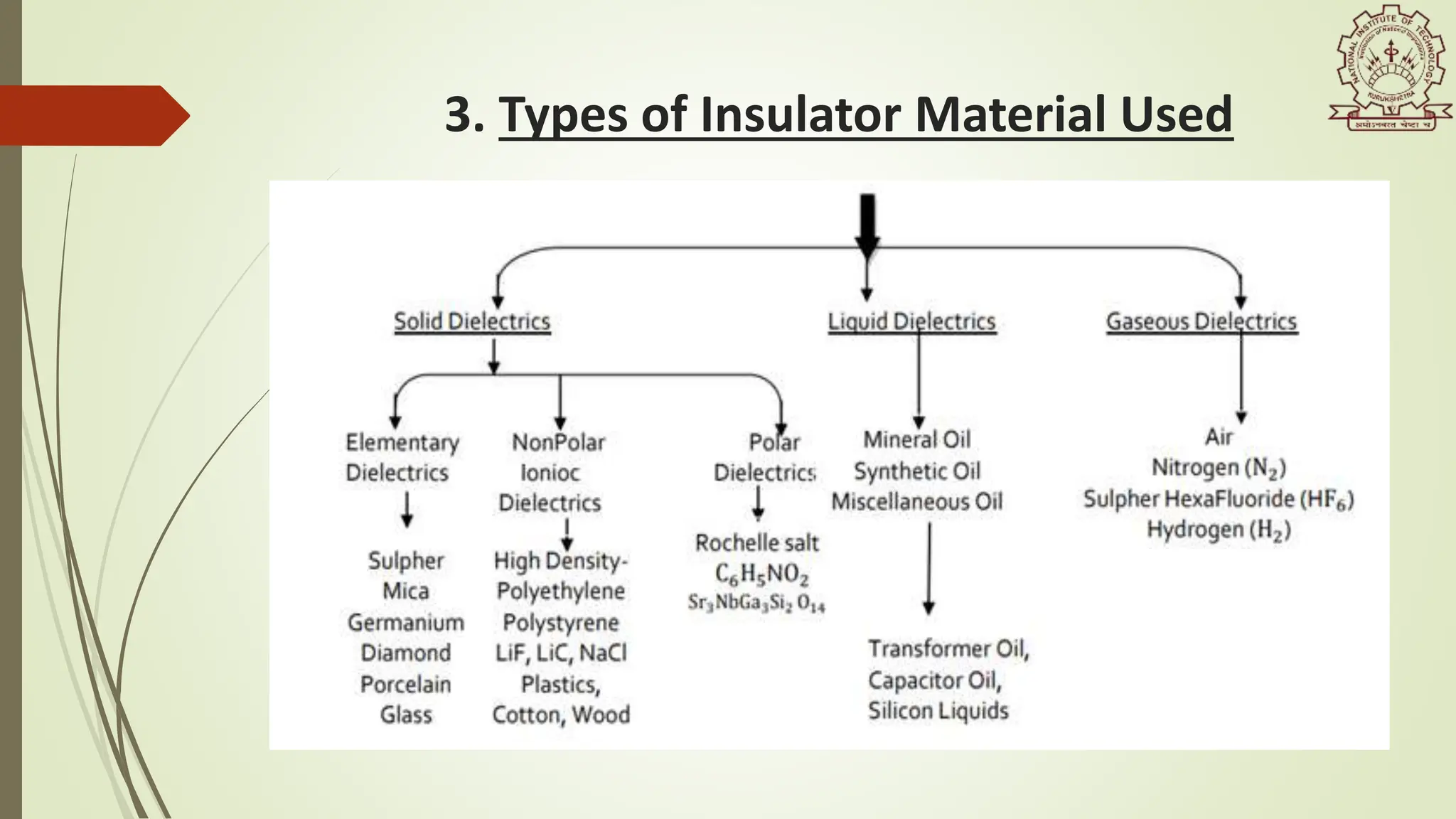
![1. Introduction
An insulator is a poor conductor that mechanically supports
an electricity transmission line and increases the electric leakage
distance along with the striking distance. Insulators were
introduced because of the needs of the telegraph industry in the
1850s. [1]
OR
According with IEC-60050-471, an insulator is: “a device intended for electrical
insulation and mechanical fixing of equipment or conductors which are subject
to electric potential differences”. [2]](https://image.slidesharecdn.com/dthve-32014306-240611173653-b13514ff/75/DTHVE-Design-Testing-in-High-Voltage-Engineering-3-2048.jpg)
![2. Brief Background
late 1890s – For the first time ceramic insulators were introduced. [1]
1950s - First non-ceramic insulators were introduced, which were composed of
epoxy resins.[1]
late 1970 and early 1980 - Polymer insulators were used primarily as special
designs for extreme applications at a premium cost to the utilities.
In 1991 the first composite insulators having a silicone rubber housing were used
as inter-phase spacers for 66-kV duty,
In 1994 their use was extended to 275-kV service with a unit 7 m in length--the
world's largest.](https://image.slidesharecdn.com/dthve-32014306-240611173653-b13514ff/75/DTHVE-Design-Testing-in-High-Voltage-Engineering-4-2048.jpg)
![1. IN POWER TRANSFORMERS
2. IN ROTATING MACHINES
3. IN CIRCUIT BREAKERS
4. IN CABLES
5. IN POWER CAPACITORS
6. IN HIGH-VOLTAGE BUSHINGS
7. IN FRACTIONAL HORSEPOWER MOTORS
4. Applications of Insulators [3]](https://image.slidesharecdn.com/dthve-32014306-240611173653-b13514ff/75/DTHVE-Design-Testing-in-High-Voltage-Engineering-6-2048.jpg)
![5. Basics of Design of Insulators
The electrical breakdown of an insulator due to excessive voltage can occur in
one of two ways:
1. Puncture voltage
2. Flashover voltage
High voltage insulators are designed with a lower flashover voltage than
puncture voltage, so they will flashover before they puncture, to avoid damage.
High voltage insulators for outdoor use are shaped to maximize the length of the
leakage path along the surface from one end to the other, called the Creepage
length, to minimize these leakage currents.[4]](https://image.slidesharecdn.com/dthve-32014306-240611173653-b13514ff/75/DTHVE-Design-Testing-in-High-Voltage-Engineering-7-2048.jpg)
![6. Design of Insulators for various apparatus
6.1 Design of Insulators for Overhead Lines
For the conventional design transmission lines the insulation problems depend
on the following 3 factors[7]-
1. Limitation of switching overvoltage
2. Occurrence of overvoltage close to design value die to fault or switching
operation
3. The possible non-linearity of the performance of long insulator strings
at service voltage under pollution conditions.](https://image.slidesharecdn.com/dthve-32014306-240611173653-b13514ff/75/DTHVE-Design-Testing-in-High-Voltage-Engineering-8-2048.jpg)
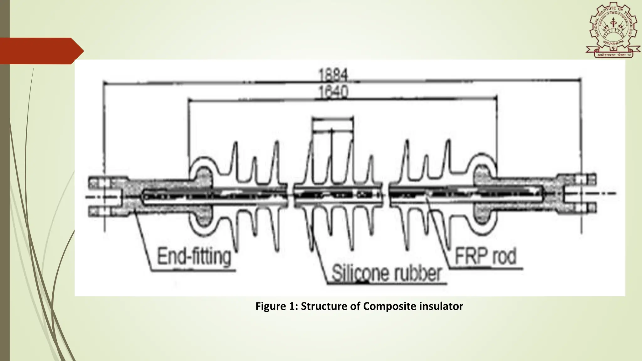
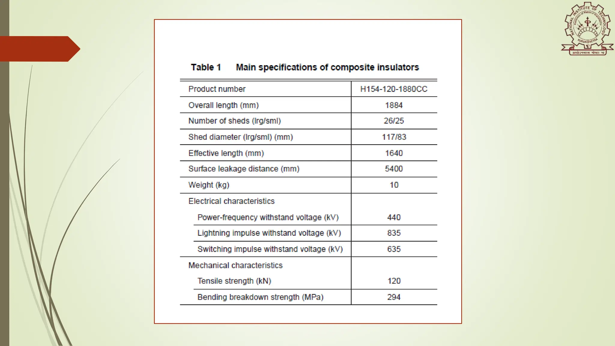
![ The most widely used insulators in the overhead lines is Composite insulators.
It is because of it’s weather resistance,which is virtually permanent, and its
hydrophobic properties, which allow improvement in the maximum withstand
voltage of pollution.
DESIGN OF COMPOSITE INSULATORS
In the figure 1, the basic structure of an composite insulator used in OH line is
shown. The core is of FRP (Fibre Reinforced Polymer) to distribute the tensile
load. The reinforcing fibers used in FRP are glass (E or ECR) and epoxy resin is
used for the matrix. [5]](https://image.slidesharecdn.com/dthve-32014306-240611173653-b13514ff/75/DTHVE-Design-Testing-in-High-Voltage-Engineering-9-2048.jpg)
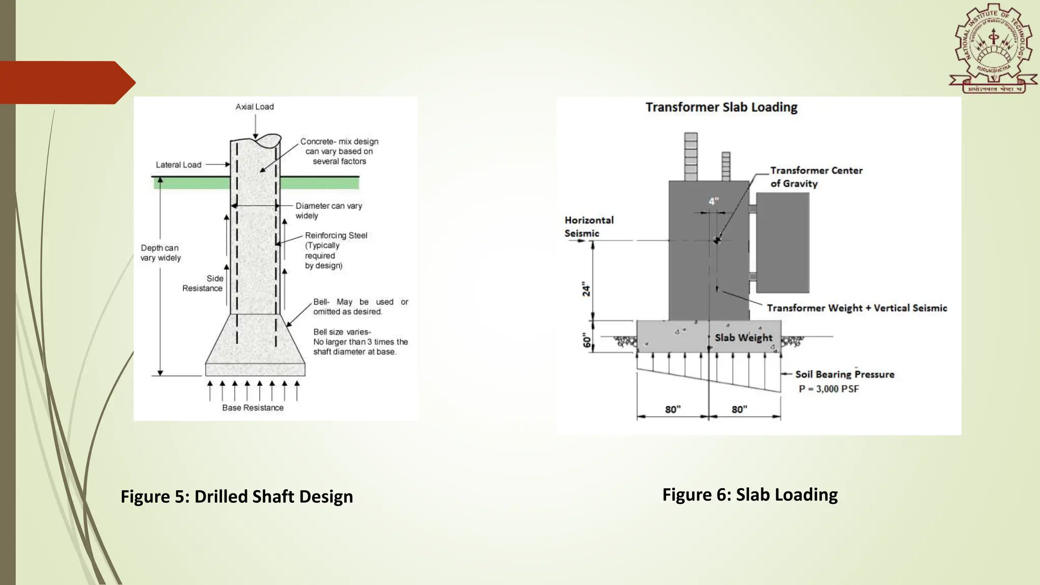
![Types of Foundations Insulation Design [7]
Drilled shafts
1. It is constructed by auguring, drilling, or coring a hole in the ground, placing
reinforcing steel, and filling with concrete
2. Drilled shafts are best suited to resist overturning shears and moments
3. It is more economical than other types because of the “assembly line”
installation procedure
4. Common size for substation foundation ranges from 24 inches to 60 inches in
diameter, in 6- inch increments. Drilled shafts above 84 inches in diameter are
typically installed in 12-inch increments with a maximum diameter of 120
inches available for extreme substation applications.](https://image.slidesharecdn.com/dthve-32014306-240611173653-b13514ff/75/DTHVE-Design-Testing-in-High-Voltage-Engineering-18-2048.jpg)
![6.4 Design of Electric Power Transmission Tower
A typical electric power transmission tower is a steel lattice structure which is used to
prop overhead power lines right from the electric power generating station switchyard to
electric load substations[8].
The Power Grid Corporation of India Limited (PGCIL) - key organization entrusted within
Indian Power Sector framework for implementing and performing all kind of assignments
related with design, installation, operation and smooth evacuation of electric power
through EHV Transmission Systems network [8].
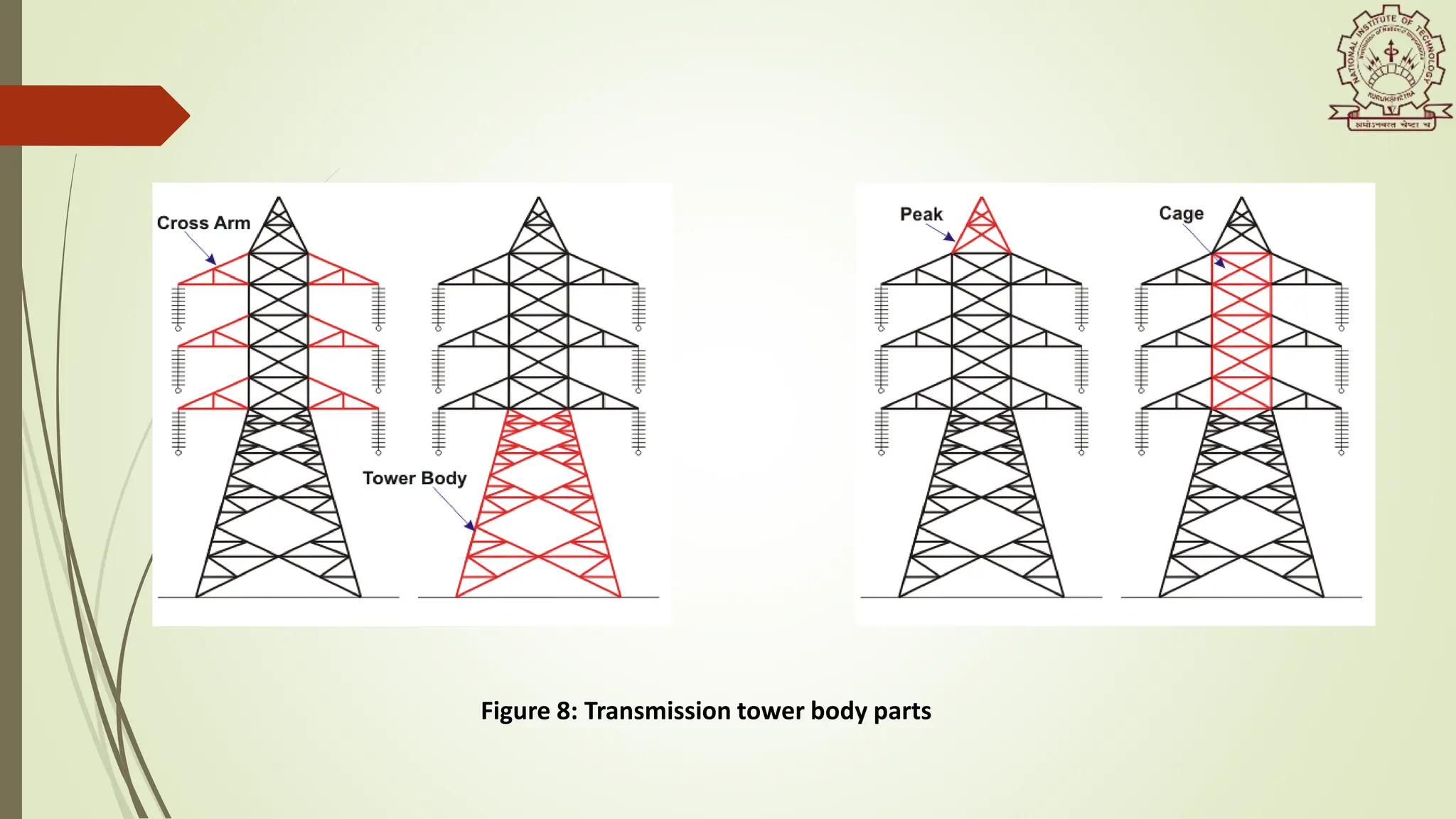
Transmission tower body parts
1. The peak of the transmission tower
2. The cross arm of the transmission tower
3. The boom of transmission tower
4. Cage of transmission tower
5. Transmission Tower Body
6. Leg of transmission tower
7. Stub/Anchor Bolt and Baseplate assembly of the transmission tower.](https://image.slidesharecdn.com/dthve-32014306-240611173653-b13514ff/75/DTHVE-Design-Testing-in-High-Voltage-Engineering-24-2048.jpg)
![Figure 9: Permissible values of ground and
horizontal clearance [8]
Figure 10: Indian standards on Tower Design [8]](https://image.slidesharecdn.com/dthve-32014306-240611173653-b13514ff/75/DTHVE-Design-Testing-in-High-Voltage-Engineering-27-2048.jpg)
![7. Recent Development
The recent trend in the development of the insulator material is the HYBRID
Insulator.
This development is emerging due to extreme environment pollution condition,
which can lead to electrical activity on the insulators including current leakage.
WHAT IS HYBRID INSULATOR ?
According to IEC 62896 [1], Hybrid insulators consist of an insulating core bearing
the mechanical load, protected by a polymeric housing.
Hybrid insulators are used as overhead line, post or hollow core equipment
insulators](https://image.slidesharecdn.com/dthve-32014306-240611173653-b13514ff/75/DTHVE-Design-Testing-in-High-Voltage-Engineering-30-2048.jpg)
![Figure 12: Chart explaining hybrid definition [9]
Figure 13: PPC Santana hybrid insulator[9]](https://image.slidesharecdn.com/dthve-32014306-240611173653-b13514ff/75/DTHVE-Design-Testing-in-High-Voltage-Engineering-31-2048.jpg)
![Figure 14: Comparison of various insulators [10]](https://image.slidesharecdn.com/dthve-32014306-240611173653-b13514ff/75/DTHVE-Design-Testing-in-High-Voltage-Engineering-33-2048.jpg)
![References
[1] Mustafa Ali, He Yadong and Jiang Lilong 2017/10/01. Design and testing of an improved
profile for silicone rubber composite insulators. IEEE Transactions on Dielectrics and Electrical
Insulation.
[2] https://www.inmr.com/insulator-design-standards-operating-parameters/
[3] Naidu MS, Kama Raju V 2013. High Voltage Engineering 5e. McGraw Education Pvt. Ltd.
[4] Holtzhausen, J.P. High Voltage Insulators, IDC Technologies. Retrieved February 16, 2009.
[5] Satoshi Kobayashi, Yutaka Matsuzaki ,Hiroshi Masuya, Yoshihiro Arashitani and Ryuzo Kimat
1999. Development of Composite Insulators for Overhead Lines
[6] Dr. K.N.Ravi, N.Vasudev, A.K.Majumdar, Dr. Channakeshava 2000. Design of Line Insulation
for Transmission Line.
[7] Substation Design Volume VIII Site & Foundation Design 2015. PDH Online Course E475
[8] Atul Jaysing Patil, Arush Singh, R. K. Jarial 2019. Some Aspects of Design and Condition
Monitoring of Electric Power Transmission Towers. IJISSET
[9] Eduardo R. Hilsdorf ,Guilherme Cunha da Silva 2019. Hybrid Insulators for Distribution
Lines:Definitions, Advantages& Application Experience. INMR World Congress, U.S.A.
[10] https://www.inmr.com/technical-review-hybrid-insulators/](https://image.slidesharecdn.com/dthve-32014306-240611173653-b13514ff/75/DTHVE-Design-Testing-in-High-Voltage-Engineering-34-2048.jpg)


![[Gönen,_Turan]_Electrical_power_transmission_system2-95-132.pdf](https://cdn.slidesharecdn.com/ss_thumbnails/gnenturanelectricalpowertransmissionsystem2-95-132-240126185159-4db75461-thumbnail.jpg?width=640&height=640&fit=bounds)