This document provides instructions for building and testing a differentiator circuit using an op amp. Key points:
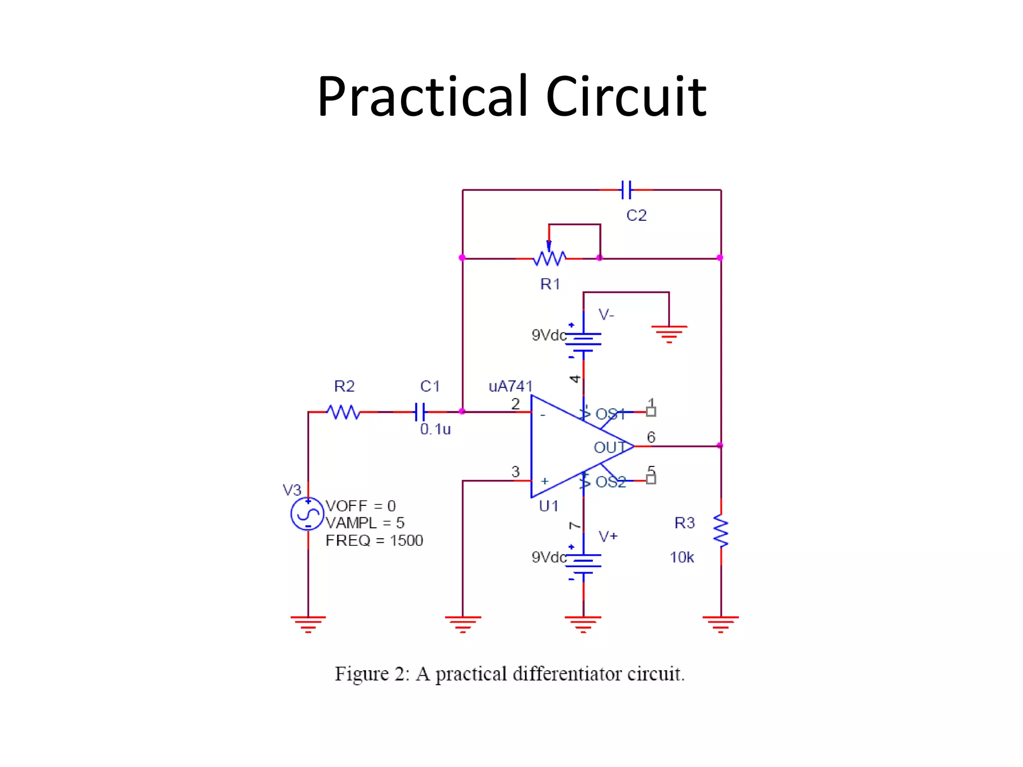
- The circuit uses an LM356 op amp instead of the diagrammed uA741. Resistors and capacitors can be combined to achieve desired values.
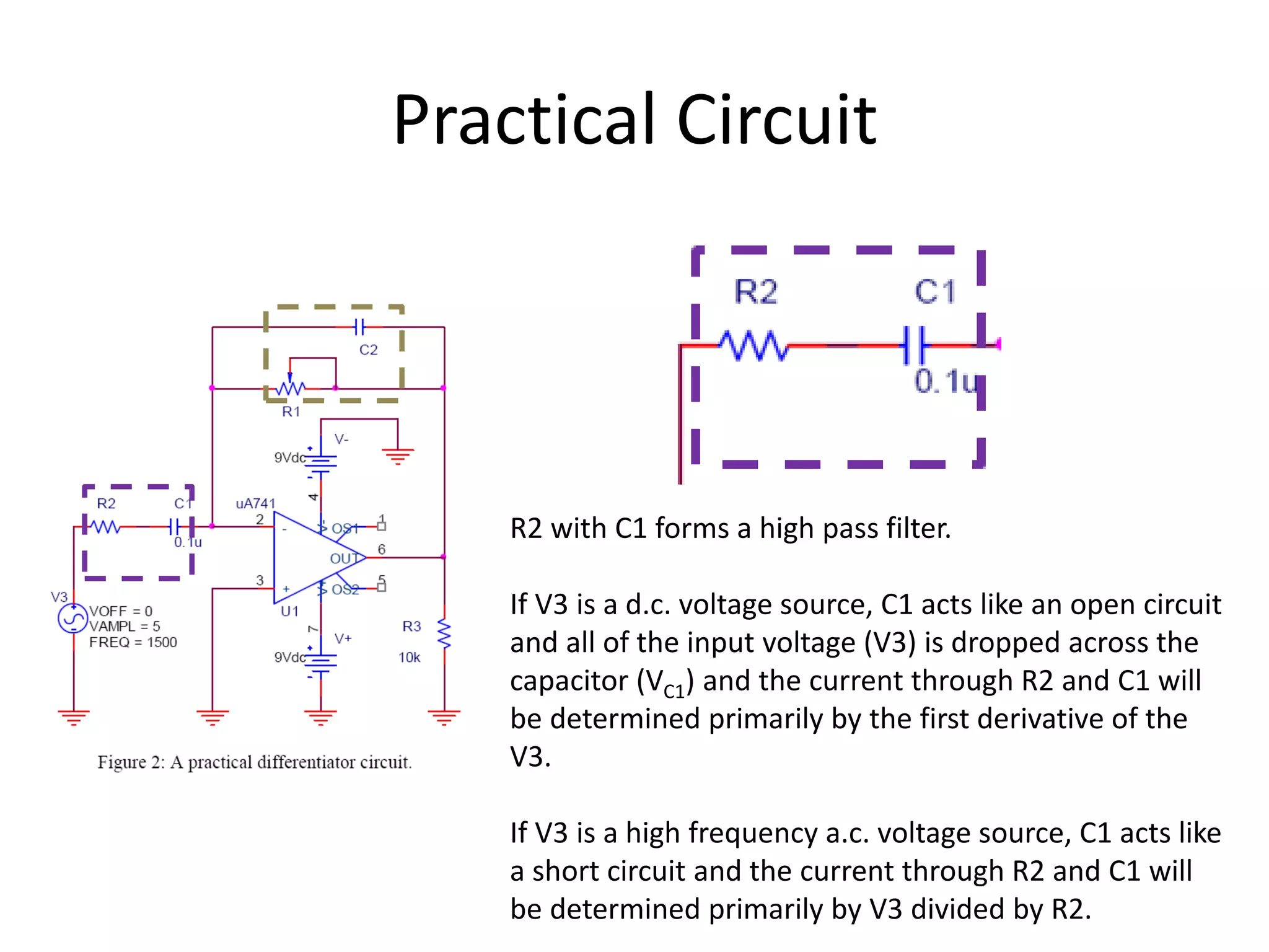
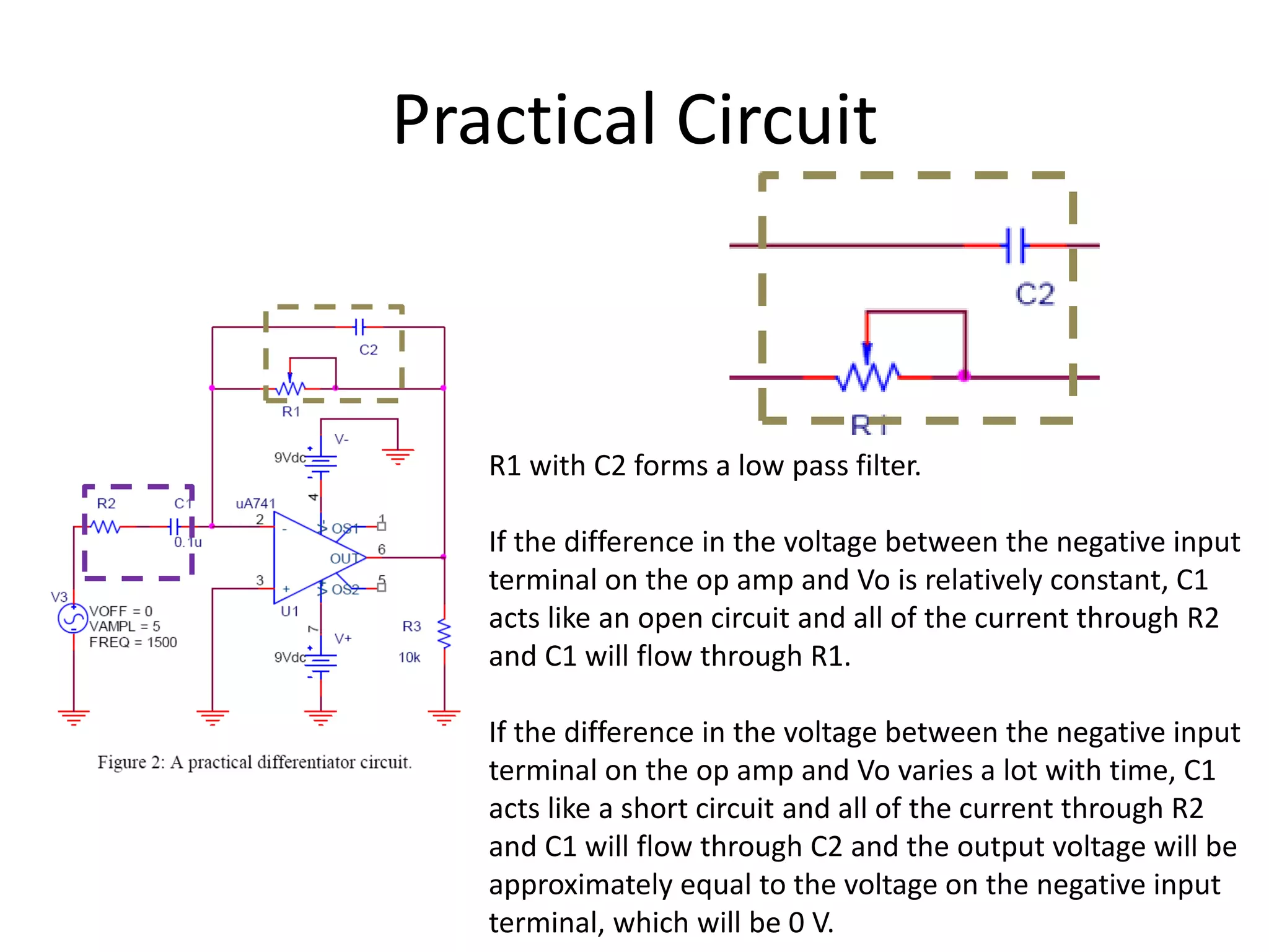
- A series resistor and feedback capacitor are added to the ideal differentiator circuit to form high-pass and low-pass filters, stabilizing the circuit and reducing noise.
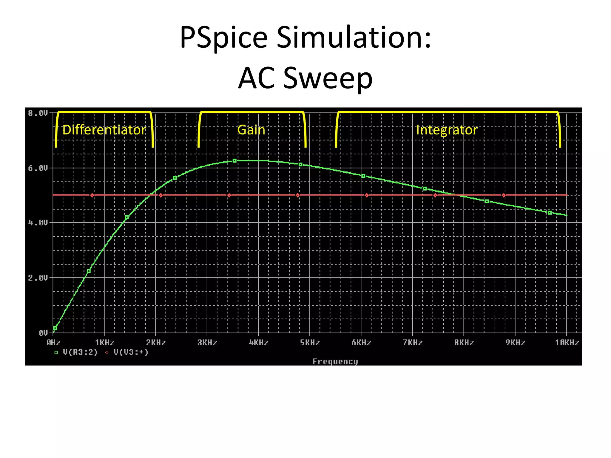
- As frequency increases, the capacitor acts less like an open circuit and more like a short circuit. This changes the circuit's behavior from a differentiator to an inverting amplifier to an integrator.
- Phase shift between input and output will vary from 90°


![iC
i = 0
iR iR + iC + i =0
where i = 0mA
iC =C1 dV3/dt
iR = [0V – Vo]/R1
Vo = -R1C1 dV3/dt](https://image.slidesharecdn.com/differentiator-220827170159-55ecd050/75/Differentiator-ppt-5-2048.jpg)