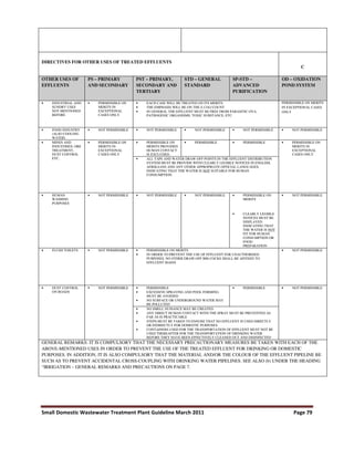
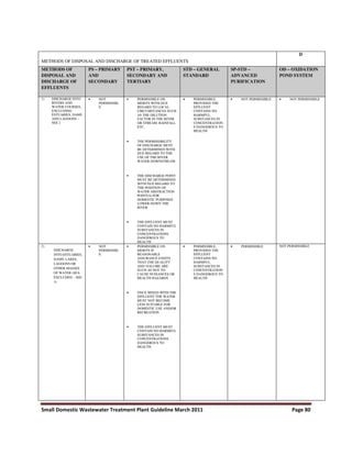
This document provides guidelines for designing small wastewater treatment plants up to 100 m3/day. It outlines the relevant legislative framework that must be considered, including the Constitution, National Environmental Management Act, National Water Act, Water Services Act, and Environment Conservation Act. The document discusses site selection criteria, staff facilities, health and safety, and operation and maintenance requirements. It also provides flow sheets and decision making processes for wastewater treatment plant design.


![Small Domestic Wastewater Treatment Plant Guideline March 2011 Page 54
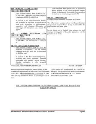
The Life Cycle Cost sheet gives us the cost of Wastewater treatment for 30 years period when
rehabilitation is performed every 10 years on the system.
Life Cycle Cost (No Maintenance):
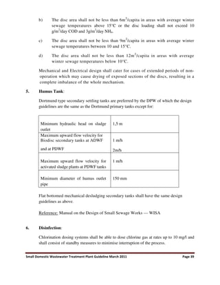
Alternate Life Cycle Cost is achieved for no rehabilitation on the system. The difference in the
life cycle cost with maintenance and no maintenance is obtained.
5.2 LIFE CYCLE COST MODEL FOR WATER, WASTEWATER SYSTEMS
A Life Cycle Cost (LCC) model for operating and maintaining wastewater sewer system has
been developed at the Center Grouting Materials and Technology (CIGMAT) at the University
of Houston, Houston, TX.
The LLC model is based on population and average household occupancy with the essential
components of water and wastewater systems identified and divided into sectors such as housing,
commercial, educational and recreational facilities. Life cycle cost includes transportation,
maintenance and rehabilitation of water and wastewater systems to control exfiltration in water
systems and infiltration in wastewater systems over the life cycle period.
The model can be used to compare different rehabilitation and maintenance scenarios and
identify the most cost effective approach to rehabilitate and maintain water and wastewater
systems. The model (LCC-CIGMAT) has been calibrated using published data on various water
and wastewater systems.
Advancements in technology have led to new cost effective methods being developed for the
inspection and rehabilitation of wastewater systems, which have made rehabilitation and
maintenance a cost effective alternative to replacement/new construction. With the correct
features, a LCC model can be used to compare various rehabilitation and maintenance plans and
new construction cost [Vipulanandan et al., 2005]. There are a number of models used for
wastewater system design, but most if not all of these models have not incorporated the LCC or
infiltration [Ardit, 1999]. Also, the GASB 34 (Governmental Accounting Standards Board
Statement # 34) requires reports of the asset value of the wastewater system (the best estimate of
the main components of the system).
Hence, there is need for developing new models to overcome some of the current shortcomings
and to estimate the extent and needs of a wastewater system based on population.
Objective
The study was developed to determine the LCC for water and wastewater systems. The specific
objectives are:](https://image.slidesharecdn.com/designguidlineforsmallwastewatertr1-230720085923-88619a62/85/Design_guidline_for_Small_Waste_Water_Tr-1-pdf-61-320.jpg)
![Small Domestic Wastewater Treatment Plant Guideline March 2011 Page 55
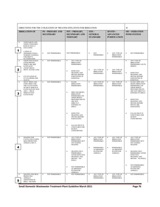
1. To identify the important parameters that influences the cost of water and wastewater
systems;
2. To develop a LCC model for a selected life cycle period (10 to 50 years);
3. To incorporate the various rehabilitation and maintenance methods to identify the most
cost effective plan; and
4. Calibrate and verify the model with published data.
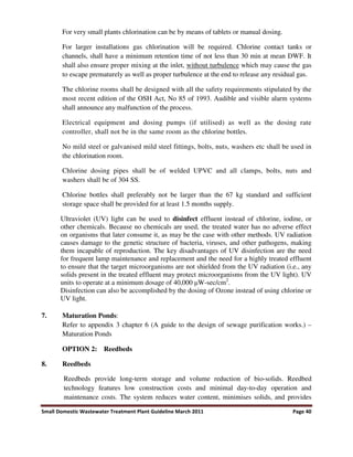
Model development
A spreadsheet model in MS Excel was developed based on the population and average household
density [CIGMAT, 2003]. The population of a city was divided in these basic units: (1) Housing
units (H); (2) Industrial park (I); (3) Commercial establishment (C); (4) Educational
establishments (E); and (5) Recreation and other facilities (R).
The model comprises several modules on an input sheet for the user to enter values specific to a
selected city (default values are provided); a basic model worksheet to estimate the size of the
wastewater system (length of sewer line, number of manholes, connections, pipe joints); daily
wastewater flow in the system; amount of infiltration; and cost associated with treatment and
transportation.
A capital cost worksheet estimates the cost for a new wastewater system. The rehabilitation
section lays out the rehab plan of the city over the life cycle study period for the wastewater
system and calculates the cost for rehabilitation for different rehabilitation plans. The Life Cycle
Cost section analyzes the life cycle cost of the wastewater system based on the rehabilitation and
the operation and maintenance (O & M) plans selected for the city.
Individual components of the wastewater system were estimated based on all of the elements.
Estimating the sewer length, infiltration and LCC are discussed in detail.
Pipe Length (PL)
The total pipe length (water or sewer) comprises main lines and trunk lines.
PL = [PL.sub.m] + [PL.sub.t]
Where
[PL.sub.m] = Main Pipe Line
[PL.sub.t] = Trunk Pipe Line
Main Pipe Line ([PL.sub.m])
Main sewer lines connect to trunk sewers. The default pipe sizes for main sewer lines range from
203 to 305 millimeter in diameter.](https://image.slidesharecdn.com/designguidlineforsmallwastewatertr1-230720085923-88619a62/85/Design_guidline_for_Small_Waste_Water_Tr-1-pdf-62-320.jpg)
![Small Domestic Wastewater Treatment Plant Guideline March 2011 Page 56
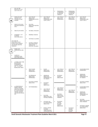
[PL.sub.m] = [n.summation over (i=1)] [a.sub.i] [H.sub.i] + [n.summation over (i=1)] [b.sub.i]
[C.sub.i] + [n.summation over (i=1)] [c.sub.i] [E.sub.i] + [n.summation over (i=1)] [d.sub.i]
[R.sub.i] + [e.sub.i] ln
Where
i = number of sectors for the wastewater system under study.
H = number of Housing units in each sector.
I = number of Industrial units in each sector.
C = number of Commercial units in each sector.
E = number of Educational establishments in each sector.
R = number of Recreational units in each sector.
a, b, c, d, e are factors representing the length of the sewer contributed to the Main Sewer Line
by Housing units, Commercial units, Educational establishments, Recreational units and
Industrial establishments respectively. The values of a, b, c, d and e are to be obtained for each
city. The default values are a = 0.008, b = 0.015, c = 0.02, d = 0.04 and e = 0.015.
Trunk Pipe Line ([SL.sub.t])
Trunk sewer is considered as a percentage of Main Pipe Line ([PL.sub.m]). Main sewer lines are
connected to the trunk sewer line, which transports sewer to the treatment plant.
[PL.sub.t] = f[PL.sub.m]
Where f is a factor represented in terms of percentage. It is a variable needed to be obtained for
the city. Default value is 10%.
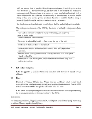
Infiltration (I)
Infiltration (for sewer) is rain induced and ground water. Infiltration can take place through
sewer lines (main sewer line, trunk sewer), manholes, pipe line joints (main sewers, trunk
sewers) and lateral joints.
I = [I.sub.sl] + [I.sub.m] + [I.sub.j]
Where [I.sub.sl], [I.sub.m], [I.sub.j]. represents infiltration through sewer lines, manholes and
joints respectively.
Infiltration at sewer line ([I.sub.sl])
Infiltration can take place at the sewer pipeline due to various reasons; cracks and root intrusion
can happen both at the trunk sewer line and main pipeline.
[I.sub.sl] = [I.sub.m] + [I.sub.t]](https://image.slidesharecdn.com/designguidlineforsmallwastewatertr1-230720085923-88619a62/85/Design_guidline_for_Small_Waste_Water_Tr-1-pdf-63-320.jpg)
![Small Domestic Wastewater Treatment Plant Guideline March 2011 Page 57
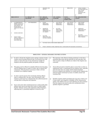
Where Im, It is infiltration at main sewer line and trunk sewer.
Infiltration at main sewer line ([I.sub.m])
Infiltration takes place along the main sewer line excluding the infiltration through pipe joints in
the main sewer line.
[I.sub.m] = u [n.summation over (j=1)] [SL.sub.m] [s.sub.j][t.sub.j]
Where
"j" represents different diameter sizes of main sewer line in millimeter.
"[t.sub.j]" is the diameter of the j size main sewer line.
"[s.sub.j]" is the percentage of main sewer line for each diameter "tj".
"[t.sub.j]" x [n.summation over (j=1)] [s.sub.j] = 1
[SL.sub.m] is the total main line sewer length.
"u" is the infiltration in litres per meter per millimeter of the diameter of the main sewer line.
Infiltration at trunk sewer line ([I.sub.m])
[I.sub.t] = u [n.summation over (k=1)] [SL.sub.t] [v.sub.j][w.sub.j]
Where
"k" represents different diameters of trunk sewer.
"v" is the diameter of various trunk sewer.
"w" is the percentage of main sewer line for each diameter represented as "t". [n.summation over
(k=1)] [w.sub.k] = 1
[SL.sub.t] is the total main line sewer length.
"u" is the infiltration per litres per square millimeter of the diameter of the main pipeline.
Life Cycle Cost
Life Cycle Cost (LCC) calculates the total cost of ownership over the life span of an asset. Initial
cost and all subsequent expected costs are included in the calculation as well as disposal (or
residual) value and any other quantifiable benefits to be derived. The larger the investment, the
more important LCC analysis becomes. The application of LCC is generally on non-revenue
producing projects where the objective is to minimize cost and maximize benefits.
Wastewater systems have a long life expectancy with a life span varying from 30 to 100 years.
The initial capital cost to set up a wastewater system for a city is high and the subsequent O & M](https://image.slidesharecdn.com/designguidlineforsmallwastewatertr1-230720085923-88619a62/85/Design_guidline_for_Small_Waste_Water_Tr-1-pdf-64-320.jpg)
![Small Domestic Wastewater Treatment Plant Guideline March 2011 Page 58
and rehabilitation cost have a significant impact on the life cycle cost of the system. An effective
Life Cycle Cost Analysis will be very beneficial for the asset management of a wastewater
system.
In this study, the following cost components are considered in the life cycle cost of a wastewater
system:
* Capital cost
* O & M cost
* Rehabilitation cost
* Residual cost
Capital cost
The capital cost includes design, planning cost, material and installation cost for pipeline,
manholes, pump stations and the treatment plant. While developing the capital cost Model,
significant variables determining the capital cost were identified. The data available in the
literature and the data provided by the city of Victoria, TX (bid data by various contractors for
wastewater construction projects) were used to verify the relationship developed in this study.
Multiple regression analysis was performed and correlation was developed between various
factors while developing the model to best estimate the capital cost of a wastewater system.
Capital Cost Model development
The model was developed by breaking down capital cost into three major components.
1) Material cost;
2) Installation cost; and
3) Miscellaneous cost (involves administrative and other expenses).
CC = [C.sub.PM] + CL + [C.sub.MH] + [C.sub.TP] + [C.sub.PS] + OC + M
Where
CC = Total capital cost
CPM = Total cost of pipe material.
CL = Total cost of pipeline installation.
CMH = Cost of manhole material installation.](https://image.slidesharecdn.com/designguidlineforsmallwastewatertr1-230720085923-88619a62/85/Design_guidline_for_Small_Waste_Water_Tr-1-pdf-65-320.jpg)
![Small Domestic Wastewater Treatment Plant Guideline March 2011 Page 59
CTP = Cost of wastewater treatment plant (WWTP) based on capacity in mega litres per day
(Ml/day) (includes material and installation cost).
CPS = Cost of pump stations based on capacity in Ml/day (includes material and installation
costs).
OC = Other costs (includes major cost components like trench system design, mobilization of
manpower and machinery, repair existing roads, traffic control, etc).
M = Miscellaneous (includes minor cost components like site preparation and taxes).
Steps in developing the model include:
* Estimate the various components of the sanitary sewer system based on the population and
average household density;
* Quantify the amount of wastewater flow based on infiltration in the existing wastewater
system;
* Develop Life Cycle Cost Analysis (LCCA) for a wastewater system with infiltration;
* Estimate infiltration cost, wastewater treatment cost and transportation cost associated with the
wastewater system;
* Estimate O & M and rehabilitation costs associated with various rehabilitation activities;
* Perform parametric study with various factors of the wastewater system and identify the most
important cost contributing factors;
* Compare various rehabilitation alternatives and perform breakeven analysis with operation cost
of the wastewater system; and
* Estimate the asset value of the wastewater system.
Calibration of model
The model was calibrated based on published wastewater system data from cities of various
population sizes from different regions in the United States [U.S. Census, 2004]. Only the sewer
length results are discussed in detail in this paper.
Sewer Length Calibration (Actual vs. Model)
The model was calibrated for the sewer length of cities from a population of 10,000 to 2 million.
The actual sewer length [Nelson et al., 1999] is compared to predicted sewer length using the
model [CIGMAT, 2003]. Of the 40 cases compared, the relationship is as follows:
Model Sewer Length = 1.005 * Actual Sewer Length.
For this relationship, the correlation coefficient (R) was 0.93.](https://image.slidesharecdn.com/designguidlineforsmallwastewatertr1-230720085923-88619a62/85/Design_guidline_for_Small_Waste_Water_Tr-1-pdf-66-320.jpg)

![Small Domestic Wastewater Treatment Plant Guideline March 2011 Page 61
LCC-CIGMAT model verification
There have been several case studies documented in literature for cities with different
populations. One example is Norfolk, VA, with a population of 260,000 [Curtis et al., 1995]. A
study on the infiltration problem was conducted based on the data provided by the city.
Information on the treatment and transportation cost were $1.40/3785 litres ($ 0.37 / kl) and
$1.29/3785 litres ($ 0.341 / kl) respectively [Curtis et al., 1995]. Based on the census data, the
household occupancy was 2.5 per unit [U.S, Census, 2004]. The model was used to generate the
data for a period of 30 years and various analyses were performed.
This study shows the changes in the percent infiltration as the spacing is increased between
various pipe joints. LCC for various infiltration reductions is compared with the repair and
treatment costs. Based on the cost results, up to 50% reduction in infiltration by repair method is
cost effective. Higher reductions in infiltration will result in greater repair cost and greater total
cost.
Conclusion
The model is based on population and household occupancy of the area that is being designed.
The lumped parameter model can be easily used to estimate size of the water and wastewater
system. The model is very flexible--it can be calibrated for a specific location by modifying the
default values provided. The model parameters are being updated by calibrating the model with
published data.](https://image.slidesharecdn.com/designguidlineforsmallwastewatertr1-230720085923-88619a62/85/Design_guidline_for_Small_Waste_Water_Tr-1-pdf-68-320.jpg)


![[Duncan_Mara]_Domestic_Wastewater_Treatment_in_Dev(z-lib.org).pdf](https://cdn.slidesharecdn.com/ss_thumbnails/duncanmaradomesticwastewatertreatmentindevz-lib-230720090216-408bdb51-thumbnail.jpg?width=640&height=640&fit=bounds)


