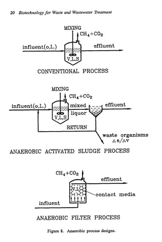
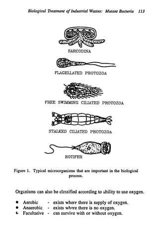
This document discusses various biological treatment techniques for industrial and municipal wastes. It provides examples of recent research using biotechnology to break down pollutants like polychlorinated biphenyls, dioxin, and 2,4-D herbicide. Mutant bacteria formulations are available commercially for treating petroleum refinery wastewater. Biological methods are effective for removing grease from clogged sewers. Overall, microorganisms play a key role in evolving to degrade both natural and man-made compounds through adaptation and new metabolic pathways.

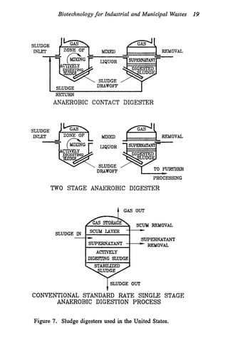
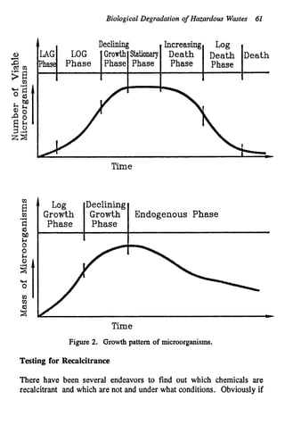


![[Duncan_Mara]_Domestic_Wastewater_Treatment_in_Dev(z-lib.org).pdf](https://cdn.slidesharecdn.com/ss_thumbnails/duncanmaradomesticwastewatertreatmentindevz-lib-230720090216-408bdb51-thumbnail.jpg?width=640&height=640&fit=bounds)


