
Recommended
More Related Content
What's hot
What's hot (20)
Similar to Design of R.C.C. Retaining Wall and Reinforced Earth Wall for 6 Meter Height
Similar to Design of R.C.C. Retaining Wall and Reinforced Earth Wall for 6 Meter Height (20)
More from ijtsrd
More from ijtsrd (20)
Recently uploaded
Recently uploaded (20)
Design of R.C.C. Retaining Wall and Reinforced Earth Wall for 6 Meter Height
- 1. International Journal of Trend in Scientific Research and Development (IJTSRD) Volume 7 Issue 3, May-June 2023 Available Online: www.ijtsrd.com e-ISSN: 2456 – 6470 @ IJTSRD | Unique Paper ID – IJTSRD57526 | Volume – 7 | Issue – 3 | May-June 2023 Page 962 Design of R.C.C. Retaining Wall and Reinforced Earth Wall for 6 Meter Height Roshan Patel1 , Mr. Hariram Sahu2 1 PG Scholar, 2 Assistant Professor, 1,2 Department of Civil Engineering, School of Engineering Eklavya University, Damoh, Madhya Pradesh, India ABSTRACT Retaining walls, which are fundamentally stiff constructions and cannot allow considerable differential settlements unless they are based on deep foundations, were almost entirely composed of reinforced concrete for a long time. The price of reinforced concrete retaining walls grew quickly as the height of the soil to be retained and the subsurface conditions deteriorated. Compared to reinforced concrete walls, mechanically stabilised earth walls (MSEW) are more affordable soil-retaining constructions that can withstand considerably greater settlements. The strength of the soil may be greatly increased by adding tensile reinforcing components (inclusions), making the vertical face of the soil/reinforcement system effectively self-supporting. Very steep slopes and vertical walls can be built securely by using a facing system to stop soil raveling between the reinforcing sections. In some circumstances, the inclusions can endure bending due to shear forces, adding to the system's stability. KEYWORDS: stiff constructions, Retaining walls, reinforced concrete, self-supporting, vertical face, shear forces How to cite this paper: Roshan Patel | Mr. Hariram Sahu "Design of R.C.C. Retaining Wall and Reinforced Earth Wall for 6 Meter Height" Published in International Journal of Trend in Scientific Research and Development (ijtsrd), ISSN: 2456- 6470, Volume-7 | Issue-3, June 2023, pp.962-973, URL: www.ijtsrd.com/papers/ijtsrd57526.pdf Copyright © 2023 by author (s) and International Journal of Trend in Scientific Research and Development Journal. This is an Open Access article distributed under the terms of the Creative Commons Attribution License (CC BY 4.0) (http://creativecommons.org/licenses/by/4.0) 1. INTRODUCTION Due to factors like construction economics and environmental safety, retaining walls or reinforced earth walls are extremely important in the building of contemporary infrastructure. Over time, several different procedures have been taken into consideration. Techniques for planning, designing, and building are continuouslybeing improved to meet a variety of requirements, including feasibility, simplicity of construction, safety, maintainability, and economics of the better soil retention system. An effective, better, and more affordable soil retention system is required for bridges, underpasses, flyovers, and any other sort of grade divider due to the increase in traffic and congestion throughout metropolitan areas. Due to safety, environmental, and economic considerations, the building of these retaining walls or reinforced earth barriers is essential to the growth of contemporary infrastructure. This important advancement was accompanied by a range of retaining wall types, designs, and building techniques. The traditional gravity retaining walls evolved into reinforced cement concrete retaining walls with buttresses or counterforts as supports over time. IJTSRD57526
- 2. International Journal of Trend in Scientific Research and Development @ www.ijtsrd.com eISSN: 2456-6470 @ IJTSRD | Unique Paper ID – IJTSRD57526 | Volume – 7 | Issue – 3 | May-June 2023 Page 963 Figure 1 Gravity Retaining Walls 1.1. Advantages of Reinforced Earth Wall Reinforced Earth walls, also known as Mechanically Stabilized Earth (MSE) walls, offer several advantages compared to traditional retaining wall systems. Here are some of the key advantages of Reinforced Earth walls: 1. Cost-effective: Reinforced Earth walls are often more cost-effective than other retaining wall systems. The use of precast concrete panels or blocks for facing and granular backfill materials reduces construction time and overall costs. 2. Easy and quick installation: The construction process for Reinforced Earth walls is relatively simple and straightforward. The precast concrete facing units or blocks can be quickly installed, and the backfill material can be easily placed and compacted. This leads to faster construction and reduced labor requirements. 3. High strength and stability: The combination of reinforced soil and the facing elements results in a high- strength and stable retaining wall structure. The reinforcements, typically in the form of geosynthetic materials like geogrids or geotextiles, provide tensile strength to the soil mass, preventing its movement and maintaining stability. 4. Flexibility and adaptability: Reinforced Earth walls can accommodate differential settlements and variations in ground conditions more effectively than rigid retaining walls. The flexible nature of the system allows it to adjust to ground movement, reducing the risk of wall failure. 5. Durability: Reinforced Earth walls are designed to withstand various environmental conditions, including freeze-thaw cycles, seismic events, and corrosion. The use of high-quality materials and appropriate design considerations can ensure the long-term durability and performance of the wall. 6. Aesthetically pleasing: Reinforced Earth walls offer design flexibility and can be customized to meet aesthetic requirements. The facing elements can be finished with various textures, colors, or patterns, allowing the wall to blend harmoniously with the surrounding environment. 7. Sustainable solution: The use of granular backfill materials and geosynthetic reinforcements in Reinforced Earth walls promotes sustainable construction practices. These materials can be locally sourced and have a lower environmental impact compared to other wall systems. Additionally, the durability and long lifespan of Reinforced Earth walls contribute to their sustainability. It's worth noting that while Reinforced Earth walls have many advantages, the suitabilityof this type of retaining wall system depends on specific site conditions and project requirements. Professional engineering analysis and design are necessary to ensure the optimal use of Reinforced Earth walls in any given project. 1.2. Disadvantages of Mechanically Stabilized Earth Wall Mechanically Stabilized Earth (MSE) walls, also known as Reinforced Earth walls, have several advantages, but they also come with certain disadvantages. Here are some of the potential drawbacks associated with MSE walls: 1. Complexity of design and construction: Designing and constructing MSE walls require specialized engineering expertise. The process involves detailed analysis of soil conditions, loadings, and reinforcement requirements. If not designed and constructed properly, MSE walls can fail, leading to costly repairs or even collapse.
- 3. International Journal of Trend in Scientific Research and Development @ www.ijtsrd.com eISSN: 2456-6470 @ IJTSRD | Unique Paper ID – IJTSRD57526 | Volume – 7 | Issue – 3 | May-June 2023 Page 964 2. Cost of materials: MSE walls typically require the use of geosynthetic reinforcement materials, such as geogrids or geotextiles, which can add to the overall cost. Additionally, the precast concrete facing panels or blocks used for the wall facing can also contribute to the expense. While MSE walls can provide long-term cost savings, the initial investment can be higher compared to other retaining wall options. 3. Drainage considerations: Proper drainage is critical for the performance and stability of MSE walls. Inadequate drainage can lead to increased hydrostatic pressure behind the wall, potentiallycompromising its integrity. Designing and implementing an effective drainage system can add complexity to the construction process. 4. Limited applicability for certain soil conditions: MSE walls are typicallysuitable for granular or cohesive soils. However, certain soil conditions, such as highly organic or expansive soils, may not be well-suited for MSE wall construction. In such cases, alternative retaining wall systems may be more appropriate. 5. Height limitations: The height of MSE walls may be limited due to factors such as soil strength, facing element capacity, and reinforcement requirements. Beyond a certain height, additional reinforcement or alternative retaining wall systems may be necessary, increasing the complexity and cost of the project. 6. Visual aesthetics: While MSE walls can be designed with some customization options for facing elements, they may not offer the same level of aesthetic flexibility as other types of retaining walls. The precast concrete panels or blocks used for facing can have a utilitarian appearance, which may not be suitable for projects with specific aesthetic requirements. 7. Environmental considerations: The production and use of geosynthetic materials in MSE walls have environmental implications. The manufacturing process of geosynthetics requires energy and resources, and their disposal at the end of their lifespan can present challenges. However, the use of locally sourced and recycled materials can help mitigate these concerns. It's important to note that the disadvantages mentioned above are general considerations, and the suitability of MSE walls depends on specific project requirements and site conditions. Consulting with experienced engineers and conducting thorough site assessments are crucial to determine the most appropriate retaining wall solution for a given project. 1.3. Objective of Stabilized Earth Wall The objective of a stabilized earth wall is to provide a stable and durable structure for retaining soil or creating a barrier to control erosion. The primary goal is to prevent soil movement and maintain the stabilityof the retained soil mass. Here are the key objectives of a stabilized earth wall: 1. Retaining soil: The main objective of a stabilized earth wall is to retain soil and prevent it from moving or collapsing. By providing structural support, the wall helps to resist the lateral pressure exerted by the soil, especially in sloping areas or where there is a significant height difference. 2. Preventing erosion: Stabilized earth walls are often used to control erosion and prevent the loss of soil due to water runoff or other environmental factors. The wall acts as a barrier to protect the underlying soil from erosion caused by wind, water, or other erosive forces. 3. Creating usable space: In some cases, stabilized earth walls are used to create usable space by leveling or terracing sloping areas. The wall allows for the creation of flat surfaces that can be utilized for various purposes such as building construction, agriculture, landscaping, or recreational areas. 4. Ensuring safety: One of the key objectives of a stabilized earth wall is to ensure the safety of structures, infrastructure, and people in areas prone to soil movement or landslides. The wall provides stability and reduces the risk of slope failures, which can be hazardous and cause property damage or injuries. 5. Minimizing environmental impact: Stabilized earth walls aim to minimize the environmental impact associated with soil erosion and slope instability. By preventing soil movement and erosion, these walls help preserve the natural landscape, protect ecosystems, and prevent sedimentation in nearby water bodies. 6. Long-term durability: Another objective of stabilized earth walls is to provide a long-lasting and durable solution. The use of suitable stabilization techniques, materials, and proper design ensures the structural integrity of the wall over time, reducing the need for frequent maintenance or replacement. 7. Design of Reinforced Earth wall and R.C.C Retaining Wall for different heights. 8. Calculating the Quantity of various components of the retaining wall and reinforced earth wall 9. Calculating the cost of Retaining wall and Reinforced Earth Wall at different heights. 10. Calculation of quantities and cost for various types of reinforced earth wall with different type of reinforcing material.
- 4. International Journal of Trend in Scientific Research and Development @ www.ijtsrd.com eISSN: 2456-6470 @ IJTSRD | Unique Paper ID – IJTSRD57526 | Volume – 7 | Issue – 3 | May-June 2023 Page 965 It's important to note that the specific objectives of a stabilized earth wall may vary depending on the project requirements, site conditions, and the desired outcomes. Professional engineering and design expertise are essential to ensure that the objectives are met effectively and efficiently. 2. LITERATURE REVIEW Basudhar et al. (2007) had sought to identify the geosynthetic reinforced earth retaining walls with the lowest cost design that could withstand both static and dynamic loads. Their research has shown that the expense associated with MCU facing units makes MSE walls built with geo-grids more expensive than those built with geo textiles. For walls less than six metres in height (between three and six metres), it is typically noted that the geogrid wall shows higher cost in the range of 20 to 30 percent, while for walls longer than six metres in height, the rise is in the range of 10 to 20 percent. Rajpaksha (2008) Reinforced earth barriers are becoming more and more common. By retaining the lateral ground pressure by metal strips, reinforced earth walls are built. The soil pressure in the reinforced earth walls is resisted by metal strips. The author investigated several equations that maybe constructed to calculate the lateral earth force acting on a facing unit. Additionally, he has investigated and examined the equations used to calculate the metal-soil friction as well as the horizontal force on the facing unit. By providing a design example to determine the length of the metal strips and solving the problem at hand, it is possible to determine the relationship between the metal-soil friction and the vertical effective stress acting on the strip, the area of the metal strip, and the friction angle between metal and soil. Shekarian et al. (2008) Selecting earth pressure is required in order to design retaining walls using traditional methods. Different theories on the distribution of earth pressure for retaining walls are put forth, however in reinforced soil, this distribution differs from that in unreinforced soil. The extent and distribution of lateral wall displacement are crucial elements in pressure distribution. In these types of walls, the vertical spacing between anchors, the slope of the anchors, the wall stiffness, and the shear resistance of the soil may all affect the displacement of the wall and the distribution of earth pressure. The degree of pressure reduction brought on by mass reinforcement has been examined in this study. Even though this publication identifies the various techniques for estimating earth pressure, several finite element analyses performed, and their outcomes assessed. In compared to a wall without reinforcement, numerical analysis of a rigid reinforced wall with an anchor revealed that the pressure on the wall is reduced as a result of parameters like stiffness, length, number, and distance of anchors. Additionally, the findings of the research demonstrated that soil reinforcement alters the wall displacement curve and lowers the average wall displacement. Tatsuoka (2008) In Japan, permanent geosynthetic-reinforced soil (GRS) retaining walls (RWs) with a full height rigid face have been built for highways as well as railways, including high-speed train lines, from roughly 20 years ago. More than 100 kilometres of traditional cantilever RWs and steel-reinforced soil RWs have been replaced with this kind of GRS RW. Many RWs of this sort were also built to replace classic type RWs and embankments that fell after previous earthquakes and high rains, even though most of them are new walls. Many bridge abutments with geosynthetic-reinforced backfill have been built by utilising this technique. The most recent design, known as the GRS Integral Bridge, consists of a continuous girder connected to two RC facings with layers of geosynthetic reinforcement in the backfill. Yang et al. (2009) a cast-in-situ concrete-rigid facing geogrid reinforced soil retaining wall of the Gan (Zhou)- Long (Yan) railway main line of China that was being built under my supervision. The reinforced soil wall confronting the reinforcement, the lateral earth pressure, the vertical foundation pressure, and the horizontal facing deformation were all evaluated. The vertical foundation pressure of a reinforced soil retaining wall is not linear along the length of the reinforcement; it is highest in the centre and progressively decreases at the top and bottom. The experiments showed that the active lateral earth pressure is greater than the lateral earth pressure that exists within the reinforced soil wall, which is non-linear along height. Ahmadabadi and Ghanbari (2009) had researched the novel method using the horizontal slice method to calculate the active earth pressure on retaining walls with reinforced and unreinforced cohesive-frictional backfill. The suggested approach demonstrates the non-linear distribution of active earth pressure fluctuation with wall depth in cohesive-frictional soils. For cohesive-frictional soils, the angle of failure wedge rises linearly as the cohesive strength of the soil increases. There is very little difference between the analytical results from the suggested approach and those from earlier studies and the AASHTO method. In order to determine the active earth pressure, tensile force of reinforcement, and angle of failure wedge for unreinforced and reinforced walls in cohesive-frictional soil, the analytical technique described can be employed.
- 5. International Journal of Trend in Scientific Research and Development @ www.ijtsrd.com eISSN: 2456-6470 @ IJTSRD | Unique Paper ID – IJTSRD57526 | Volume – 7 | Issue – 3 | May-June 2023 Page 966 Ling et al. (2009) had centred on the outcomes of finite element modelling of a full-scale geosynthetic soil retaining wall made of concrete blocks that was built at the Public Works Research Institute in Japan. It was decided to include a nonlinear hyperbolic geosynthetic model into a computer programme that could simulate the behaviour of the interaction between the soil and the structure. While the block-block and soil-block interactions were modelled using interface components, the soil was approximated using a hyperbolic model. The finite element model is capable of modelling the building behaviour of concrete-block geosynthetic- reinforced soil structures, according to a comparison of numerical and measured experimental data. Bathurst et al.( 2009) The goal of the research is to establish a novel working stress technique for calculating the reinforcement loads in geosynthetic reinforced soil walls. It does this by synthesising the authors' previous work. Prior to achieving this goal, careful back-analyses of a database of instrumented and monitored full-scale field and laboratory walls are used to show that the Simplified Method currently being used in North America produces estimates of the volume of reinforcement needed to produce satisfactory long-term wall performance that are overly conservative. By carefully interpreting reinforcement strains and converting strain to load using an appropriately chosen reinforcement stiffness value, the novel approach is calibrated against observed in-situ wall reinforcement loads. Diwalkar (2020) In general, retaining walls are strong, inflexible structures designed to sustain soil masses laterally. This review study's goal is to comprehend the examination of retaining walls. The major consideration in the study and design of retaining walls is lateral earth pressure. Regarding the retaining wall's stability against tipping over and sliding, as well. Kong et al. (2020) Structures called reinforced retaining walls are built horizontally to withstand soil pressure by using the frictional force that the backfill imparts. Because they offer high safety and economic efficiency, reinforcements are used. But insufficient reinforcement might cause collapse, while too much reinforcement hurts the economy. So it's crucial to choose the right kind, size, and spacing of reinforcements. However, at actual sites, the same number of reinforcements are frequently put despite the fact that the stress and fracture processes in the straight and curved sections of reinforced soil retaining walls differ. Such a strategy may cause the wall to crumble or make it less economically viable. Nouman et al. (2023) For practising geotechnical/civil engineers, predicting settlement of GRS abutments under service loading circumstances is a difficult and complex issue. In order to anticipate the settling of the GRS abutments, a unique hybrid artificial intelligence (AI)-based model known as ANN-HHO, which combines artificial neural networks (ANN) and Harris hawks' optimisation (HHO), was created in this research. Support vector regression (SVR), Gaussian process regression (GPR), relevance vector machine (RVM), sequential minimal optimisation regression (SMOR), and least-median square regression (LMSR) are five other strong intelligent models that were built and contrasted with the ANN-HHO model. Predictive power, reliability, and Robust statistical testing, ranking criteria, a multi-criteria approach, uncertainity analysis, and sensitivity analysis (SA) were used to evaluate the model's robustness. Additionally, many sizable independent experimental investigations on GRS abutments published in the scientific literature were used to support the model's prediction accuracy. The obtained results showed that the ANN-HHO model produced improved performance in comparison to competing models and reasonably accurately forecasted the settling of GRS abutments. In order to investigate the in-service performance of GRS abutments, geotechnical and civil engineers use it as one of their prediction tools for making preliminary decisions. Finally, the model has been reduced to a straightforward mathematical formulation allowing straightforward hand computations, and it has been demonstrated to be more time and cost-effective than experimental testing and numerical simulations. Yang et al. (2023) the effectiveness of geosynthetic-reinforced soil (GRS) walls with marginal backfill exposed to rainwater infiltration was investigated using a series of model experiments. In order to avoid the GRS wall failing owing to high rainfall, the efficiency of improvement measures—such as reducing reinforcement spacing and increasing sand cushion thickness—was assessed. Throughout the test, it was kept an eye on how the distribution and change of the volumetric water content, porewater pressure, wall deflection, and reinforcement tensile strain. Using the bright dyeing approach, it was possible to see how the wetting front was moving and how the sand cushions were serving their purpose of draining. In the baseline scenario, when rain fell, the wall started to sag, which caused the possible failure surface to slowly recede. As soon as the possible failure surface shifted past the strengthened zone, the upper reinforcement layers began to come away, which caused the GRS wall to collapse in a compound failure scenario. Reduced reinforcing spacing and thicker sand cushions significantly decreased wall deflection and improved wall stability. Sand cushions used in between
- 6. International Journal of Trend in Scientific Research and Development @ www.ijtsrd.com eISSN: 2456-6470 @ IJTSRD | Unique Paper ID – IJTSRD57526 | Volume – 7 | Issue – 3 | May-June 2023 Page 967 reinforcement layers can help slow down water penetration and lessen the buildup of porewater pressure inside the wall. Based on the findings, recommendations for building GRS walls that can withstand rain are also made. 3. DESIGN MEHODOLOGY OF R.C.C. RETAINING WALL AND REINFORCED EARTH The design methodology for a reinforced concrete (R.C.C.) retaining wall and a reinforced earth wall for a height of 6 meters will involve different approaches. Here is a general overview of the design methodology for each type of wall: 3.1. Design Methodology for R.C.C. Retaining Wall 1. Determine design parameters: Gather information about the site conditions, including soil properties, groundwater levels, and surcharge loads. These parameters are crucial for designing the wall. 2. Calculate active and passive earth pressures: Determine the magnitude and distribution of earth pressures acting on the retaining wall. Use methods such as Rankine's theory or Coulomb's theory to calculate active and passive earth pressures based on the soil properties. 3. Design the wall structure: Select appropriate wall dimensions, including height, base width, and stem thickness. Design the reinforcement layout based on the calculated bending moments and shear forces along the wall. Use structural engineering principles and codes to ensure the wall can withstand the applied loads and remain stable. 4. Check stability: Perform stability analysis to ensure the wall can resist overturning, sliding, and bearing capacity failures. Consider factors such as foundation design, global stability, and the effects of water pressure if applicable. 5. Provide drainage: Incorporate proper drainage systems to control water accumulation behind the wall. This helps to alleviate hydrostatic pressure and minimize the risk of wall failure. 6. Construction considerations: Develop construction drawings, detailing reinforcement layout, specifications for concrete mix, and wall facing if applicable. Coordinate with contractors and construction professionals to ensure the design is implemented correctly. 3.2. Design Methodology for Reinforced Earth Wall 1. Gather site information: Collect relevant information about soil properties, groundwater levels, surcharge loads, and any other site-specific factors influencing the design. 2. Determine the facing system: Select the appropriate facing system for the reinforced earth wall. This may involve precast concrete panels, concrete blocks, or other facing options based on aesthetic and functional requirements. 3. Calculate the required reinforcement: Perform geotechnical analysis to determine the reinforcement requirements. This involves evaluating the stability of the reinforced soil mass, calculating tensile forces, and selecting appropriate reinforcement materials such as geosynthetics. 4. Design the backfill: Choose suitable granular backfill materials and determine their compaction requirements. Consider factors such as friction angle, compaction characteristics, and long-term stability. 5. Stability analysis: Conduct stability analysis to ensure the reinforced earth wall can resist the applied loads, including earth pressures and any additional surcharges. Check for factors such as wall overturning, sliding, and bearing capacity. 6. Construction considerations: Prepare construction drawings and specifications, including reinforcement layout, facing system details, and backfill specifications. Coordinate with contractors to ensure proper construction techniques, compaction, and installation of reinforcements. 3.3. Design Procedure of Retaining WallTop of Form Designing a reinforced earth retaining wall involves several steps and considerations. While it is challenging to provide a comprehensive generalized flow chart without specific project details, I can outline a basic procedure that covers the key steps involved. Please note that this flow chart is a general guideline and may need to be adjusted based on the specific requirements of your project. Here's a generalized flow chart for designing a reinforced earth retaining wall using reinforcement steel: Determine the site conditions, including soil properties, water table, and slope stability analysis. Obtain information on the required wall height, width, and backfill properties. Identify any additional loads or design considerations specific to your project. Perform preliminary design: Determine the design methodology and code requirements to be followed.
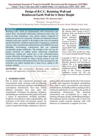
- 7. International Journal of Trend in Scientific Research and Development @ www.ijtsrd.com eISSN: 2456-6470 @ IJTSRD | Unique Paper ID – IJTSRD57526 | Volume – 7 | Issue – 3 | May-June 2023 Page 968 Conduct an initial stability analysis to assess the overall stability of the wall. Select the appropriate wall type based on site conditions and project requirements (e.g., gravity wall, reinforced soil wall, etc.). Calculate the required strength and stability of the retaining wall. Analyse the internal and external forces acting on the wall. Select an appropriate reinforcement type (e.g., steel strips, geogrids) based on design requirements and project constraints. Determine the facing system, including the type of facing material (e.g., concrete panels, segmental blocks). Calculate the facing stability, considering the applied loads, connection details, and structural requirements. Specify the facing reinforcement (if required) to provide stability and distribute the forces. Analyse and design the reinforcement elements: Figure: 1 Flowchart of R.C.C. Retaining Wall
- 8. International Journal of Trend in Scientific Research and Development @ www.ijtsrd.com eISSN: 2456-6470 @ IJTSRD | Unique Paper ID – IJTSRD57526 | Volume – 7 | Issue – 3 | May-June 2023 Page 969 Selection of Structural Types Selection of Foundation Type Determination of Design Condition Examination of Earquake Effect Assumption of Sectional Shape of Wall Calculation and Conbination of Loads Stability Analysis for Wall and Foundation Ground Figure: 2 Flowchart of Retaining Wall Design 4. R.C.C. RETAINING WALL FOR HEIGHT OF 6.0 M Height of embankment above GL =6.0 m The values for Grade of concrete, S.B.C. of soil, Density of soil, Grade of steel, Density of Concrete, Friction Coefficient, Active earth Pressure, Angle of wall friction, Angle of internal, Coefficient of active earth Pressure (Ka) is kept same as that for RCC retaining wall for the height of 4.0m. Dimensions of Retaining Wall Provide minimum Depth of Foundation = 1.0 m Height of wall above ground level = 6.0 m Overall depth of Foundation (H) = 7.0 m Base Width (b) = 3.5 m Toe Projection = 1.05 m Thickness if Base Slab = 0.585 m Top width of Stem = 0.2 m Thickness of Stem = 0.583 m Heel Projection = 1.867 m Clear stem of height (h) = 6.4 m Horizontal Pressure = 163.33 KNm Bending Moment = 190.55 KNm Total Weight = 793.52 Kn.m Stability against Overturning FOS = 3.74 > 1.4 Hence Safe Stability against sliding FOS = 0.974 <1.4 Hence Shear Key is required Check for maximum pressure at toe Safe Maximum pressure at toe Pmax = 108.58 KN/m2 < SBC
- 9. International Journal of Trend in Scientific Research and Development @ www.ijtsrd.com eISSN: 2456-6470 @ IJTSRD | Unique Paper ID – IJTSRD57526 | Volume – 7 | Issue – 3 | May-June 2023 Page 970 Hence Safe Pmin = 93.37 KN/m2 < SBC Hence Safe Design of Stem Provide overall Depth = 500 mm Clear Cover = 50 mm Provide depth = 450 mm Area of steel r/f = 2477.88 mm2 Assume spacing as 130 mm c/c Distribution of Steel R/F Average thickness of wall = 391.67 mm Area of steel = 470 mm Steel to be provided in each face = 235 mm Spacing to be provided = 330 mm c/c Check for Shear Hence No Shear Reinforcement is required Design of Shear Key Provide a 200 mm deep shear Key 5. Design for reinforced RE Wall with metallic strips for Height of 6.0 m Height of embankment above GL = 6.0 m The values for Grade of concrete, S.B.C. of soil, Density of soil, Grade of steel, Density of Concrete, Friction Coefficient, Active earth Pressure, Angle of wall friction, Angle of internal, Coefficient of active earth Pressure (Ka) is kept same as that for Reinforced RE wall for the height of 4.0 m. Dimensions of Wall Provide minimum Depth of Foundation = 1.0 m Height of wall above ground level = 6.0 m Overall depth of Foundation (H) = 7.0 m Base Width = 4.2 m Lateral earth Pressure = 33.33 KNm Horizontal Pressure = 147.00 KN/m Assume horizontal and vertical spacing of strips 1.0m Width of strips = 0.1 m Density of material to be used in filling = 18 Kn/m2 Yield strength in steel = 2, 50, 000 Kn/m2 Height of strips to be considered for RE wall Considering clear cover from foundation = 0.5 m Considering clear cover from top = 0.5 m Height in which reinforcement is to be provided = 6.0 m No of reinforcements = 6.0 m Force at reinforcement = 51 Kn Provide thickness as 15.0 m Stability against sliding Safe Stability against Overturning Safe Bearing Pressure Safe
- 10. International Journal of Trend in Scientific Research and Development @ www.ijtsrd.com eISSN: 2456-6470 @ IJTSRD | Unique Paper ID – IJTSRD57526 | Volume – 7 | Issue – 3 | May-June 2023 Page 971 6. COST OF RETAINING WALL AT 6m HEIGHTS Table 1 Retaining Wall for 6 m Height Item No as per SOR 2014 Description Unit Rate Quantity Amount 3.2 Earth work in Excavation Excavation in ordinary rock by Manual Means Excavation in ordinary rock including loading in a truck and carrying of excavated material to embankment site with all lifts and leads Cum 226.00 40.00 9,040 9.1 PCC M-15 in Foundation Plain cement concrete M-15 mix with crushed stone aggregate 40 mm nominal size mechanically mixed, placed in foundation and compacted by vibration including curing for 14 days. Cum 4,209.00 5.25 22,097 13.6 Plain/Reinforced cement concrete in sub- structure complete as per drawing and technical specifications. Cum 6,588.00 52.48 345,751 13.7 TMT / HYSD Reinforcement: in Retaining walls as per Technical Specification Clause 1600. MT 75,415.00 4.62 348,298 Total Amount 725,187 Table 2 RE FACIA WALL for 6m Height Sl. No. Description of works Unit Length Width Height/ Depth Qty Total Quantity A Earth work in Excavation cum 10.000 4.700 1.000 47.000 TOTAL Earth work 47.000 47.000 B GSB Below Leveling PAD GSB Below Leveling PAD cum 10.000 4.700 0.150 7.050 TOTAL GSB 7.050 7.050 C PCC M-15 Grade Concrete M-15 G. Con. Leveling Pad cum 10.000 0.450 0.150 0.675 TOTAL M-15 0.675 0.675 C RE wall Fill And Geo Grid i RE wall Fill cum 10.000 4.200 7.000 294.000 ii RE wall facia panel Sqm 10.000 1.000 7.000 70.000 iii Geo Grid cum 10.000 4.200 7.000 294.000 658 658 7. CONCLUSIONS 1. To study the cost effectiveness of the Retaining wall and reinforced earth walls the Retaining wall has been designed for a height of 6 m. 2. As it is a well-known fact that the retaining wall tend to fail after a certain height. To stabilize the Retaining walls, counter forts are added to the retaining wall and the same has been designed for the height of 6m Similarly the Reinforced Earth walls also known as RE walls have been designed for the heights of 6m 3. A soil-reinforced structure's site-specific costs depend on a variety of variables, including the amount of ground that has to be cut and filled, the wall or slope's height and type, the soil type present, the backfill material available, the appearance of the facing panel, and whether it will be used temporarily or permanently. 4. It has been shown that for higher heights, reinforced concrete retaining walls are often more costly than R walls with precast concrete facings. 5. The methods used to design various types of outwardly and internally stabilised walls have been described in depth, with examples taken from the RCC retaining wall/Counter fort. Respectively, retaining walls and RE walls have
- 11. International Journal of Trend in Scientific Research and Development @ www.ijtsrd.com eISSN: 2456-6470 @ IJTSRD | Unique Paper ID – IJTSRD57526 | Volume – 7 | Issue – 3 | May-June 2023 Page 972 been evaluated and developed for a range of heights. 6. The amount of the walls is then determined, and a cost estimate for their 6 metre length has been made. For the specific geometry and stress parameters taken into account in this study, it has been discovered that internally stabilised walls (RE walls) are much more cost-effective than externally stabilised walls, or retaining walls. 7. The major contribution in the cost difference is attributed to the huge amount of concrete and steel bars usually required in the retaining walls as compared to RE walls due to the basic design difference. 8. The retaining wall is designed ion the basis that the earth is retained behind the wall and major loading is ion the wall due to earth back fill. Whereas, in its counterpart i.e. the Reinforced Earth Wall the friction between the earth and the reinforcement shares the load which is then transferred to the ground. 9. The reinforcement thus develops tension and the earth behaves as if it has cohesion REFERENCES [1] AASHTO, (1997) Standard Specifications for Highway Bridges, Div. 1, Sect. 5, Retaining Walls, Washington, DC, 89pp, 1997. [2] Al, H.O., Muhunthan, B., (2006) Numerical procedures for deformation calculations in the reinforced soil walls. Geotextiles and Geo- membranes 24 (1), 52–57, 2006 [3] Alborz, Siavash. (2016). STUDY ON HORIZONTAL DISPLACEMENT OF RESTRAINED EXCAVATION WALLS BY CANTILEVER RETAINING WALL. 10.5281/zenodo.56029. January 2016 DOI:10.5281/zenodo.56029 [4] Al-Hattamleh, O., Muhunthan, B., (2006) Numerical procedures for deformation calculations in reinforced soil walls. Geotextiles and Geomembranes 24 (1), 52–57, 2006 [5] Allen, T.M., Christopher, B.R., Holtz, R.D., (1992) Performance of a 12.6 m high geotextile wall in Seattle, Washington, geosynthetic- reinforced soil retaining walls. In: Wu, J.T.H. (Ed.), Balkema, Proceedings of the International Symposium on Geosynthetic- Reinforced Soil Retaining Walls, Denver, Colorado, USA, pp. 81–100, 1992 [6] Anderson, R.B. (1993) Construction Considerations for Geogrid-Segmental Block Mechanically Stabilized Earth Retaining Walls, Transportation Research Record, 1414:12−15, 1993 [7] Aylin Ece Kayabekir, Zülal Akbay Arama, Gebrail Bekdaş, Sinan Melih NigdeliZong Woo Geem (2020).” Eco-Friendly Design of Reinforced Concrete Retaining Walls: Multi- objective Optimization with Harmony Search Applications”, Sustainability 2020, 12(15), 6087; https://doi.org/10.3390/su12156087 Received: 15 June 2020 / Revised: 11 July 2020 / Accepted: 27 July 2020 / Published: 29 July 2020 [8] Azad, A., Yasrobi, S., Pak, A., (2008) Seismic active earth pressure distribution behind rigid retaining walls. Soil Dynamics and Earthquake Engineering 28 (5), 365–375, 2008 [9] B. Ceranic, C.Fryer and R.W. Banies. (2001) an application of simulated annealing to the optimum design of reinforced concrete retaining structures. Computers and Structures, 79: 1569-1581, 2001 [10] Baker, R., Klein, Y., (2004) An integrated limiting equilibrium approach for design of reinforced soil retaining structures, part I: formulation. Geotextiles and Geomembranes22 (3), 119–150, 2004 [11] Bathurst, R.J., Jarrett, P.M., Benjamin, D.J.R.S., (1993) A database of results from an incrementally constructed geogrid-reinforced soil wall test. In: Proceedings of Soil Reinforcement: Full Scale Experiments of the 80’s. ISSMFE/ENPC, Paris, France, pp. 401– 430, 1993b [12] Bathurst, R.J., Simac, M.R., (1994) Geosynthetic reinforced segmental retaining wall structures in North America. In: Proceedings of the Fifth International Geosynthetics Conference, Singapore, SEAC- IGA, Keynote Lecture Volume, pp. 29–54, 1994. [13] Bathurst, R.J., Simac, M.R., Christopher, B.R., Bonczkiewicz, C., (1993) A data-base of results from a geosynthetic reinforced modular block soil retaining wall. In: Proceedings of Soil Reinforcement: Full Scale Experiments of the 80’s. ISSMFE/ ENPC, Paris, France, pp. 341– 365, 1993a [14] Berg, R.R., Meyers, M.S., (1997) Analysis of the collapse of a 6.7m high geosynthetic- reinforced wall structure. In: Proceedings of the
- 12. International Journal of Trend in Scientific Research and Development @ www.ijtsrd.com eISSN: 2456-6470 @ IJTSRD | Unique Paper ID – IJTSRD57526 | Volume – 7 | Issue – 3 | May-June 2023 Page 973 Geosynthetics ’97. IFAI, Roseville, MN, pp. 85104, 1997. [15] Berg, R.R., Nelson, B., (2000) Practical implications of MBW unit-geosynthetic connection strength requirements. In: Proceedings of the 14th GRI Conference. GAI Publications.Folsom, PA, pp. 307–322, 2000 [16] Muhammad Nouman Amjad Raja, Syed Taseer Abbas Jaffar, Abidhan Bardhan, Sanjay Kumar Shukla, [17] Predicting and validating the load-settlement behavior of large-scale geosynthetic-reinforced soil abutments using hybrid intelligentmodeling,=JournalofRockMechanics andGeotechnicalEngineering,https://doi.org/10. 1016/j.jrmge.2022.04.012.(https://www.science direct.com/science/article/pii/S1674775522001 093) [18] Kuo-Hsin Yang, Hsin-Ming Wu, Ting-Ling Tseng, Chungsik Yoo,Model tests of geosynthetic-reinforced soil walls with marginalbackfillsubjectedtorainfall,Geotextiles andGeomembranes,https://doi.org/10.1016/j.ge otexmem.2022.12.002.(https://www.sciencedire ct.com/science/article/pii/S0266114422001340)