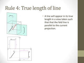
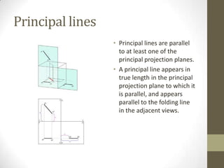
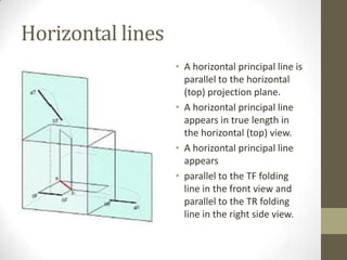
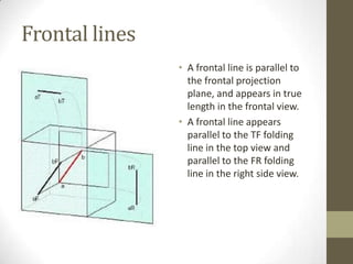
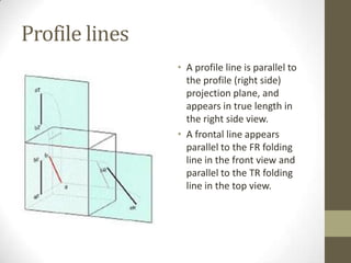
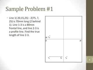
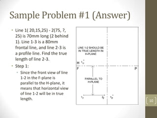
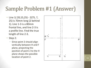
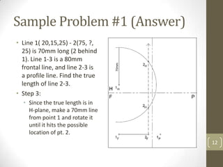
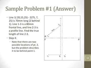
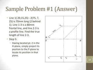
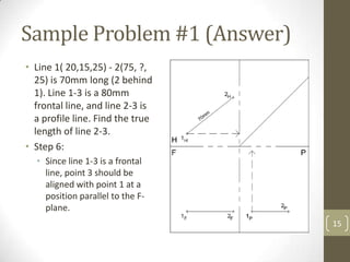
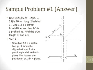
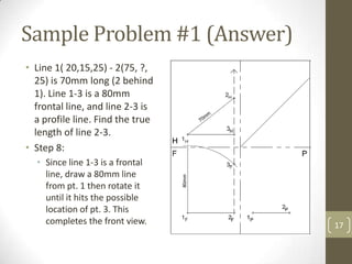
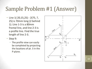
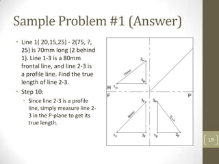
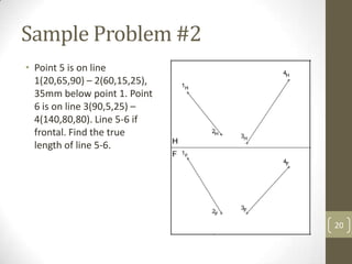
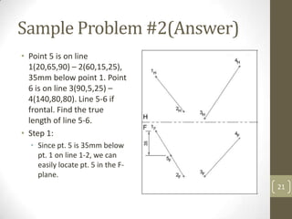
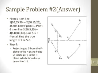
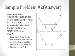
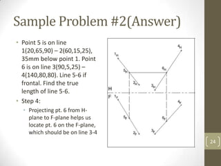
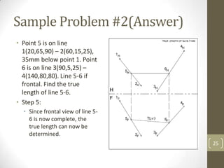
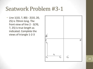
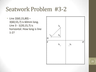
This document provides information on principal lines in multi-view drawings. It defines three types of principal lines - horizontal, frontal, and profile lines. It explains that principal lines appear in their true length in the principal projection plane they are parallel to. It provides two sample problems demonstrating how to determine the true length of lines by analyzing their orientation relative to the projection planes and using principles of multi-view drawings. It concludes with two practice problems for the reader to complete the missing views.
This document provides information on sectional views in engineering drawings. It defines what a sectional view is, how cutting planes work, and the different types of section views including full sections, half sections, offset sections, and broken-out sections. It also discusses guidelines for section lining techniques, including line placement, materials, and special cases for things like ribs, webs, and rotated features. The document aims to explain the principles and applications of section views in detailed technical drawings.
This document provides an overview of orthographic projection and multiview drawings. It discusses the purpose of multiview drawings in graphically representing 3D objects in 2D. Key concepts covered include projection planes, lines of sight, and different types of projections. The document also examines how an object's features like edges and surfaces are identified and projected in different views. Examples of multiview drawings are provided to illustrate these concepts. Guidelines for line conventions in hidden line and center line drawings are also presented.
This document provides information about engineering graphics and orthographic projections. It begins by introducing projections of points, lines, planes and solids. It then discusses coordinates and quadrants. The majority of the document explains how to draw orthographic projections of various geometric elements including points in different quadrants, straight lines in different orientations, planes in different positions, and solids. It provides examples and step-by-step instructions for creating projections of these elements in first, second, third and fourth quadrants. The document concludes by introducing different types of solids and announcing details about an upcoming exam.
This document provides instructions for projecting plane figures given their position relative to the horizontal and vertical planes. It begins by describing what information is typically provided in projection problems involving planes: a description of the plane figure and its position relative to the HP and VP defined by an inclination. Common steps for solving these problems are outlined, including making initial assumptions, projecting the inclined surface, and projecting the inclined edge. An example problem of projecting a rectangle with a surface inclined to the HP and edge inclined to the VP is shown. The key steps of the procedure are to first draw projections assuming the initial position, then incorporate the surface inclination, and finally the edge inclination.
This document discusses sections and developments of solids. It begins by defining sectioning a solid as cutting it with an imaginary cutting plane to understand its internal details. Two common section planes are described. Developments of solids are defined as unfolding the hollow object to show its unfolded sheet shape. Engineering applications of developments in sheet metal industries are provided. The document then discusses important terms in sectioning and provides illustrations. It explains developments of different solids and includes nine problems demonstrating sections and developments of prisms, cones, and frustums with step-by-step solutions.
This document discusses orthographic projections and engineering drawing fundamentals. It covers topics like multiview projection concepts using the glass box method, how to project points, lines, planes and full objects, and line conventions for hidden lines and center lines. Key concepts are projecting an object by revolving it or moving the observer, and representing all sides including invisible surfaces in an orthographic projection.
This document discusses the projection of planes. It defines a plane as a two-dimensional object with length and breadth but negligible thickness. There are two main types of planes: perpendicular and oblique. Perpendicular planes are perpendicular to one of the principal planes of projection, while oblique planes are inclined to both. The document provides examples of different orientations of perpendicular planes and their appearances in top and front views. It also gives an example problem showing the projection of an inclined plane.
This document discusses perspective projection and provides examples of how to draw perspective views of objects. Perspective projection involves drawing three-dimensional objects as they appear to the human eye using a station point and picture plane. It describes the key elements used, such as the ground plane, station point, picture plane, and visual rays. Examples are provided to demonstrate how to draw perspective views of basic shapes like pyramids, blocks, and cubes using either the visual ray method or vanishing point method. Tips are included on identifying visible and invisible edges and completing the perspective projection drawing.
1) The document describes various geometric solids and their projections including prisms, pyramids, cylinders, cones, and frustums.
2) It provides examples of different solids placed in various positions and orientations and outlines the step-by-step process to draw their projections.
3) The examples illustrate how to draw projections when axes of solids are inclined to the planes of projection at various angles and when parts of solids intersect projection planes.
This is Mechnicial Engineering's subjrct technicial drawing slides
topic name is Projection of lines.
this would help you in how you draw front side and top view of a line.
Conversion of Pictorial View into Orthographic Views.pptNjokuGabriel1
This document provides instruction on orthographic projections and how to convert pictorial views into orthographic views using first and third angle projection methods. It includes 26 examples of objects with pictorial views and instructions to draw the corresponding front, top, and side views using first angle projection. The examples demonstrate orthographic projections of different geometric shapes and solids to practice recognizing surfaces and drawing multiple views.
This document provides an overview of engineering drawing standards and conventions. It discusses the elements that make up a drawing including drawing sheets, scales, lettering, line types and more. Standards help ensure drawings clearly convey design intent to others. Lettering must have good legibility and uniformity. Common line types include visible, hidden, center and extension lines. Dimensioning and notes provide key numeric details.
Orthographic projections are a method of technical drawing where views of an object are projected onto planes perpendicular to the object. There are three principal planes - the horizontal plane, vertical frontal plane, and profile plane. Views are the front view projected on the vertical plane, top view on the horizontal plane, and side view on the profile plane. The document provides details on first and third angle projection methods, examples of orthographic projections of different objects, and terminology used in orthographic projections.
This document discusses auxiliary views in technical drawing. Auxiliary views show inclined surfaces in their true shape and size, as they appear foreshortened in regular views. To make an auxiliary view, a plane is imagined parallel to the inclined surface. A view of this auxiliary plane from a perpendicular direction shows the true shape of the surface. The document provides step-by-step instructions for constructing auxiliary views, including using a center plane reference for symmetrical objects. It demonstrates the process with examples and concludes with a practice problem.
1. The document defines axonometric and oblique projections, and explains the differences between isometric projections, drawings, and axes.
2. It provides steps for sketching in isometric views from both actual objects and multi-view drawings, including positioning axes and enclosing shapes before adding details.
3. Guidelines are given for orienting complex object features and determining which orientations are better for oblique sketching.
This document discusses different types of section views used in technical drawings, including full sections, half sections, offset sections, and assembled sections. A section view shows internal features of an object by imagining a cut through the object. Various sectioning techniques are used depending on the shape and features needed to be shown. Proper visualization of the cut and placement of section lines is important for clarity.
The document discusses isometric and oblique pictorial drawings. It defines pictorial drawings as 2D illustrations of 3D objects that show three faces in one view. There are three main types of pictorials: isometric, oblique, and perspective. Oblique pictorials start with a straight-on view of the front face and use angled parallel lines to represent depth. The two types of oblique pictorials are cavalier, which makes objects appear deeper, and cabinet, which provides a more realistic view. Isometric pictorials show three faces of a cube sharing a single point and appearing at 120 degree angles. The document provides examples and step-by-step instructions for creating isometric and ob
This document provides information on various topics related to engineering graphics including:
1. Orthographic projections from isometric views using first and third angle methods. It includes examples of drawing front, top, and side views from isometric drawings.
2. Types of lines used in drawings and their applications. Dimensioning techniques including aligned and unidirectional systems.
3. Sectioning of drawings including types of section planes and how they are represented in different views.
4. Worked examples of drawing multi-view drawings from isometrics and adding sectioning and dimensions.
The document provides information about isometric projections and how to draw isometric views of objects. It includes:
1) An introduction to isometric projections, which show all three dimensions of an object in the same view, unlike orthographic projections which only show two dimensions.
2) Details on isometric axes, lines, and planes which are used to construct isometric views.
3) Examples of how to draw isometric views of simple objects like blocks and planes given their orthographic projections, including setting up the isometric axes and scale.
4) Steps for constructing isometric views of more complex objects by splitting them into pieces.
The document discusses isometric projections and oblique projections. Isometric projections show an object with all vertical lines remaining vertical but horizontal lines drawn at a 30 degree angle. Oblique projections show depth through lines drawn at 45 degree angles, with cavalier drawings showing full scale depth, cabinet drawings at half scale, and general oblique drawings using any reasonable scale between half and full.
The document discusses the development of surfaces, which is the unfolding or flattening out of a 3D object onto a 2D plane. Developments show the true size of each surface area and are used in industries like construction to lay out material that is then folded to form the desired object. There are several methods of development including parallel line, radial line, triangulation, and approximate methods for complex surfaces. Examples are provided of developing lateral surfaces of prisms, pyramids, cylinders and cones cut by inclined planes.
Perspective is a geometric drawing technique used to represent three-dimensional objects on a two-dimensional surface. It makes objects appear smaller and closer together the further they are from the observer's eye. The horizon line marks where the sky meets the ground in the drawing. Parallel lines that are not parallel to the picture plane converge at vanishing points on the horizon line, which helps create the illusion of depth. There are different types of perspective depending on the orientation of objects to the picture plane.
The document discusses various types of technical drawings including axonometric projections, oblique projections, and isometric drawings. It explains the differences between axonometric, oblique, and isometric projections. The key steps for creating isometric sketches from actual objects and multi-view drawings are outlined, including positioning the object, defining axes, adding details, and darkening visible lines. Guidelines for orienting complex objects in isometric sketches are also provided.
This document discusses multi-view drawings and orthographic projections. It defines different line types used in drawings including visible, hidden, center, and dimension lines. It also describes different projection planes and surface orientations including normal, parallel, perpendicular, and inclined surfaces. The document provides examples of orthographic projection drawings and steps for creating multi-view drawings. It concludes with an isometric drawing quiz to test the reader's understanding.
The document classifies and describes various 3D solids. It divides solids into two groups - Group A solids have bases and tops of the same shape, while Group B solids have a pointed top called an apex. It then lists and describes specific solids in each group such as prisms, pyramids, cylinders and cones. The document also provides details on dimensional parameters, sections of solids, and steps to solve problems involving the projection of solids.
This document outlines the purpose and process of conducting a review of related literature. It discusses assessing relevant sources, organizing the literature, analyzing findings, and formatting the review. The goals are to broaden understanding of the topic, identify new ideas and approaches, and situate one's own research within the context of prior work. The review involves searching literature, evaluating sources, interpreting the literature to draw implications for one's study, and summarizing key contributions and relevance to one's own research. Care must be taken to thoroughly prepare and prevent plagiarism to ensure the review is valid and adds value.
This document discusses identifying and defining research problems. It provides examples to illustrate research and non-research problems. A research problem has a discrepancy between what is and what should be, a question about why the discrepancy exists, and at least two plausible answers. The document also outlines situations to avoid in problem selection and provides guidance on properly defining the research problem through literature reviews and establishing clear boundaries.
Research 04 ethical issues in researchTroy Elizaga
This document discusses ethical issues and principles in research including protection of participants, informed consent, privacy, and honesty. It outlines principles such as not exposing participants to harm, obtaining voluntary informed consent, maintaining confidentiality, and honest reporting. Research misconduct including fabrication, falsification, and plagiarism is also discussed. An ethics review board must approve all research to ensure these principles are followed.
Research is defined as a systematic process of collecting, analyzing, and interpreting information to increase understanding of a phenomenon. It involves clearly articulating a goal and specific plan, dividing problems into sub-problems, and collecting and interpreting data to resolve the initiating problem. Research is important for licensed professionals to ensure public health, safety and welfare. It is guided by questions or hypotheses and requires critical assumptions.
The document discusses various concepts in descriptive geometry related to locating points and lines in space. It provides instructions on how to determine the missing projection of a point given two other projections, how to project a line into other views, and how to determine the relative positions of points based on their projections. It includes examples of problems asking to locate points or complete views based on given positional descriptions and provides instructions for seatwork problems to practice these concepts.
Descriptive geometry allows representing three-dimensional objects in two dimensions using specific procedures. Gaspard Monge developed these techniques in the 1700s. Orthographic projection projects points of an object perpendicularly onto planes of an imaginary glass box to form two-dimensional top, front, and side views. Principal planes are the box faces, while auxiliary planes can be any orientation. Projecting points defines their locations by coordinates in each view, with alignments across views following specific rules.
2. Rule 4: True length of line
• A line will appear in its true
length in a view taken such
that that the fold line is
parallel to the current
projection.
3. Principal lines
• Principal lines are parallel
to at least one of the
principal projection planes.
• A principal line appears in
true length in the principal
projection plane to which it
is parallel, and appears
parallel to the folding line
in the adjacent views.
4. Types of Principal Lines
• There are three basic types of principal lines:
• Horizontal line
• Frontal line
• Profile line
4
5. Horizontal lines
• A horizontal principal line is
parallel to the horizontal
(top) projection plane.
• A horizontal principal line
appears in true length in
the horizontal (top) view.
• A horizontal principal line
appears
• parallel to the TF folding
line in the front view and
parallel to the TR folding
line in the right side view.
6. Frontal lines
• A frontal line is parallel to
the frontal projection
plane, and appears in true
length in the frontal view.
• A frontal line appears
parallel to the TF folding
line in the top view and
parallel to the FR folding
line in the right side view.
7. Profile lines
• A profile line is parallel to
the profile (right side)
projection plane, and
appears in true length in
the right side view.
• A frontal line appears
parallel to the FR folding
line in the front view and
parallel to the TR folding
line in the top view.
9. Sample Problem #1
• Line 1( 20,15,25) - 2(75, ?,
25) is 70mm long (2 behind
1). Line 1-3 is a 80mm
frontal line, and line 2-3 is
a profile line. Find the true
length of line 2-3.
9
10. Sample Problem #1 (Answer)
• Line 1( 20,15,25) - 2(75, ?,
25) is 70mm long (2 behind
1). Line 1-3 is a 80mm
frontal line, and line 2-3 is
a profile line. Find the true
length of line 2-3.
• Step 1:
• Since the front view of line
1-2 in the F-plane is
parallel to the H-plane, it
means that horizontal view
of line 1-2 will be in true
length. 10
11. Sample Problem #1 (Answer)
• Line 1( 20,15,25) - 2(75, ?,
25) is 70mm long (2 behind
1). Line 1-3 is a 80mm
frontal line, and line 2-3 is
a profile line. Find the true
length of line 2-3.
• Step 2:
• Since point 2 should align
vertically between H and F
plane, projecting the
position of point 2 to the H
plane shows the possible
location of point 2. 11
12. Sample Problem #1 (Answer)
• Line 1( 20,15,25) - 2(75, ?,
25) is 70mm long (2 behind
1). Line 1-3 is a 80mm
frontal line, and line 2-3 is
a profile line. Find the true
length of line 2-3.
• Step 3:
• Since the true length is in
H-plane, make a 70mm line
from point 1 and rotate it
until it hits the possible
location of pt. 2.
12
13. Sample Problem #1 (Answer)
• Line 1( 20,15,25) - 2(75, ?,
25) is 70mm long (2 behind
1). Line 1-3 is a 80mm
frontal line, and line 2-3 is
a profile line. Find the true
length of line 2-3.
• Step 4:
• Note that there are two
possible locations of pt. 2,
but the problem describes
it to be behind point 1.
13
14. Sample Problem #1 (Answer)
• Line 1( 20,15,25) - 2(75, ?,
25) is 70mm long (2 behind
1). Line 1-3 is a 80mm
frontal line, and line 2-3 is
a profile line. Find the true
length of line 2-3.
• Step 5:
• Having located pt. 2 in the
H-plane, simply project its
position to the P-plane to
locate its position in that
plane.
14
15. Sample Problem #1 (Answer)
• Line 1( 20,15,25) - 2(75, ?,
25) is 70mm long (2 behind
1). Line 1-3 is a 80mm
frontal line, and line 2-3 is
a profile line. Find the true
length of line 2-3.
• Step 6:
• Since line 1-3 is a frontal
line, point 3 should be
aligned with point 1 at a
position parallel to the F-
plane.
15
16. Sample Problem #1 (Answer)
• Line 1( 20,15,25) - 2(75, ?,
25) is 70mm long (2 behind
1). Line 1-3 is a 80mm
frontal line, and line 2-3 is
a profile line. Find the true
length of line 2-3.
• Step 7:
• Since line 2-3 is a profile
line, pt. 3 should be
aligned with pt. 2 at a
position parallel to the P-
plane. This locates the
position of pt. 3 in H-plane. 16
17. Sample Problem #1 (Answer)
• Line 1( 20,15,25) - 2(75, ?,
25) is 70mm long (2 behind
1). Line 1-3 is a 80mm
frontal line, and line 2-3 is
a profile line. Find the true
length of line 2-3.
• Step 8:
• Since line 1-3 is a frontal
line, draw a 80mm line
from pt. 1 then rotate it
until it hits the possible
location of pt. 3. This
completes the front view. 17
18. Sample Problem #1 (Answer)
• Line 1( 20,15,25) - 2(75, ?,
25) is 70mm long (2 behind
1). Line 1-3 is a 80mm
frontal line, and line 2-3 is
a profile line. Find the true
length of line 2-3.
• Step 9:
• The profile view can easily
be completed by projecting
the locations of pt. 3 in the
P-plane.
18
19. Sample Problem #1 (Answer)
• Line 1( 20,15,25) - 2(75, ?,
25) is 70mm long (2 behind
1). Line 1-3 is a 80mm
frontal line, and line 2-3 is
a profile line. Find the true
length of line 2-3.
• Step 10:
• Since line 2-3 is a profile
line, simply measure line 2-
3 in the P-plane to get its
true length.
19
20. Sample Problem #2
• Point 5 is on line
1(20,65,90) – 2(60,15,25),
35mm below point 1. Point
6 is on line 3(90,5,25) –
4(140,80,80). Line 5-6 if
frontal. Find the true
length of line 5-6.
20
21. Sample Problem #2(Answer)
• Point 5 is on line
1(20,65,90) – 2(60,15,25),
35mm below point 1. Point
6 is on line 3(90,5,25) –
4(140,80,80). Line 5-6 if
frontal. Find the true
length of line 5-6.
• Step 1:
• Since pt. 5 is 35mm below
pt. 1 on line 1-2, we can
easily locate pt. 5 in the F-
plane.
21
22. Sample Problem #2(Answer)
• Point 5 is on line
1(20,65,90) – 2(60,15,25),
35mm below point 1. Point
6 is on line 3(90,5,25) –
4(140,80,80). Line 5-6 if
frontal. Find the true
length of line 5-6.
• Step 2:
• Projecting pt. 5 from the F-
plane to the H-plane helps
us locate pt. 5 in the H-
plane, which should also
be on line 1-2. 22
23. Sample Problem #2(Answer)
• Point 5 is on line
1(20,65,90) – 2(60,15,25),
35mm below point 1. Point
6 is on line 3(90,5,25) –
4(140,80,80). Line 5-6 if
frontal. Find the true
length of line 5-6.
• Step 3:
• Since line 5-6 is a frontal
line, it follows that line 5-6
in the H-plane should be
parallel to the F-plane. Pt.
6 is also on line 3-4. 23
24. Sample Problem #2(Answer)
• Point 5 is on line
1(20,65,90) – 2(60,15,25),
35mm below point 1. Point
6 is on line 3(90,5,25) –
4(140,80,80). Line 5-6 if
frontal. Find the true
length of line 5-6.
• Step 4:
• Projecting pt. 6 from H-
plane to F-plane helps us
locate pt. 6 on the F-plane,
which should be on line 3-4
24
25. Sample Problem #2(Answer)
• Point 5 is on line
1(20,65,90) – 2(60,15,25),
35mm below point 1. Point
6 is on line 3(90,5,25) –
4(140,80,80). Line 5-6 if
frontal. Find the true
length of line 5-6.
• Step 5:
• Since frontal view of line 5-
6 is now complete, the
true length can now be
determined.
25
27. Seatwork Instructions:
• Use a short bond paper.
• Place margin all around at
10mm from edge of paper.
• Draw a horizontal line
20mm below top margin to
create a panel where you
will write the word
problem.
• Divide the rest of the space
in equal parts depending
on the requirement of the
problem
27
28. Seatwork Problem #3-1
• Line 1(10, ?, 80) - 2(10, 20,
25) is 70mm long. The
front view of line 2 - 3(70,
?, 25) is true length as
indicated. Complete the
views of triangle 1-2-3
28
29. Seatwork Problem #3-2
• Line 2(60,15,80) –
3(60,55,?) is 60mm long.
Line 3 - 1(20,15,?) is
horizontal. How long is line
1-2?
29