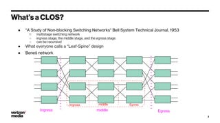
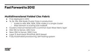
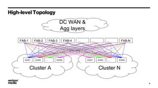
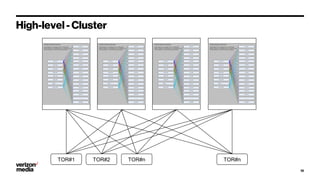
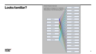
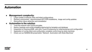
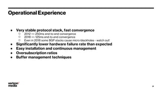
Demystifying Data Center
CLOS networks
Igor Gashinsky, Yihua He
June 2019
Overview of Yahoo’s Data Center Fabric v3
(2012-2018)
Agenda
1. What's CLOS?
2. Different CLOS topologies
3. Gory Details of our topology
4. Scaling
5. Automation
6. Operations
2
What’s a CLOS?
● “A Study of Non-blocking Switching Networks" Bell System Technical Journal, 1953
○ multistage switching network
○ ingress stage, the middle stage, and the egress stage
○ can be recursive!
● What everyone calls a “Leaf-Spine” design
● Beneš network
3
Ingress
Ingress
middle
middle
Egress
Egress
Different CLOS topologies
● Not surprisingly, most modern network hardware uses some type
of a CLOS already
○ Chassis Routers/Switches
○ Linecards
4
Virtual Chassis
5
● Spine = Fabric Card
● Leaf = Linecard
● Internal interconnect = PCB x-bar
Virtual Linecard
6
● 32 TOR’s = 32 ports
● FAB(ric) switches = Fabric Chips
● Connect to a common fabric
FAB1 FAB2 ... FABN
1 2 3 4 5 6 7 8 .. 32
NANOG 40 - Feb 2008
7
Fast Forward to 2012
Multidimensional Folded Clos Fabric
● First deployed in 2012
● 1k, 5k, 10k, 20k Node Cluster Sizes in production
○ scales to 40k, 80k, 160k, 320k nodes in a single cluster
○ blast domain vs scaling size tradeoff
● Clusters interconnected with a common East-West fabric layer
● Old: 10G to Server, 40G Core
● New: 25G to Server, 100G Core
● Layer 3, dual stack IPv4/IPv6, BGP-based
● Fully Automated provisioning, self healing system
8
Cluster A
High-level Topology
9
FAB-1 FAB-2 FAB-3 FAB-4 ... ... ... FAB-N
EGR1 EGR2 ... EGRN
Cluster N
EGRN
...
EGR2
EGR1
DC WAN &
Agg layers
10
High-level - Cluster
VC #1
TOR#1 TOR#2 TOR#n
VC #2 VC #3 VC #4
TOR#n
Looks familiar?
11
12
Physical layout
13
First Prototype - 2011
14
Actual picture
TOR perspective
● Each TOR uses a unique private
ASN
● TOR EBGP peers to a single LEF
on each of the N Virtual Chassis's
● TORs have network statements
for Lo0 and all host subnets
15
VC #1
AS64512
TOR#1
AS64513
VC #2
AS64512
VC #3
AS64512
VC #4
AS64512
TOR#2
AS64514
TOR#3
AS64515
TOR#n
AS(64512+n)
Inside the Virtual Chassis
● Each Virtual Chassis uses a private ASN
● SPN is a route reflectors to the LEF
● SPN-LEF ibgp sessions are pt-2-pt
○ update src local-interface
● SPN has network statements for all SPN-LEF
interconnects
● LEF has network statements for LEF-TOR
interconnects
● LEF uses next-hop-self for SPN-LEF ibgp
sessions
● All BGP next hop addresses are learned via bgp
○ There is no IGP inside of the VC
● All Virtual Chassis's use the same ASN
16
Cluster to fabric connectivity
● EGR = EGress Router,
○ Same class of devices as SPN/LEF
○ EGRs are like TORs
● EGRs are special
○ Each EGRs can connect to multiple
LEFs in a single VC and multiple
VCs
○ EGR can aggregate cluster
subnets
○ variation on traditional CLOS
architecture
● FABs
○ connect to EGRs in multiple
clusters
○ Use “remove-private” so that
multiple clusters can use the same
set of ASNs
○ speak eBGP to EGRs and OSPF to
higher level of devices
○ redistribute aggregated subnets
from each cluster to rest of DC
topology
17
VC #1
AS64512
TOR#1
VC #2
AS64512
VC #3
AS64512
VC #4
AS64512
TOR#2 TOR#3 TOR#n
EGR#1
AS64513
EGR#2
AS64514
EGR#3
AS64515
EGR#n
AS645xx
FAB-1 FAB-2 FAB-3 FAB-4 ... ... FAB-
N
VC #1
AS64512
TOR#1
VC #2
AS64512
VC #3
AS64512
VC #4
AS64512
TOR#2 TOR#3 TOR#n
EGR#1
AS64513
EGR#2
AS64514
EGR#3
AS64515
EGR#n
AS645xx
Incast & Buffer Pressure
18
SPINE
LEAF
TOR
● Single cluster capacity
○ Number of edge positions (TOR or EGR) = Rspn* Rlef/2, where R is switch port radix
■ Rspn= 32, Rlef= 32 => 512 position = 20K nodes
■ Rspn= 64, Rlef= 32 => 1024 positions = 40K nodes
■ Rspn= 64, Rlef= 64 => 2048 positions = 80K nodes
■ Rspn= 128, Rlef= 128 => 8192 positions = 320k nodes
○ TOR oversubscription ratio is decided by number of VCs (or number of uplinks)
■ 2VC -- 1:6, 4 VC -- 1:3, 6 VC --- 1:2, 8 VC --- 1:1.5, 12 VC --- 1:1
● Multiple clusters
○ Multiple clusters can be connected thru N-way FABs
○ Additional east-west capacity between the clusters can be added by:
■ Horizontal scaling (additional EGR’s, or additional FABs)
■ Multiple FAB planes (inc dedicated “internal” FABs for east-west traffic only)
■ Turning a FAB into a VC itself
Scaling
19
Automation
● Management complexity:
○ Large number of devices, links and initial configurations
○ Dynamic environment, asynchronized LEF/TOR installations, image and config updates
○ Device/links failure detection and remediation
● Automation is the solution
○ Treat the network with CI/CD principles
○ Device, topology and config modelling abstracted by template and database
○ Integration of inventory/DNS with Zero Touch Provisioning for initial bootstrap and configuration
○ Separation of config intent and config state, complete control loop by state machines
○ Check out our NANOG 68 presentation “Network Automation with State Machines”
20
Operational Experience
● Very stable protocol stack, fast convergence
○ 2012 => 250ms end-to-end convergence
○ 2018 => 125ms end-to-end convergence
○ Even in 2018 some BGP stacks cause micro-blackholes - watch out!
● Significantly lower hardware failure rate than expected
● Easy installation and continuous management
● Oversubscription ratios
● Buffer management techniques
21
Questions?
igor@verizonmedia.com
hyihua@verizonmedia.com
23
Demystifying Datacenter Clos

Demystifying Datacenter Clos

  • 1.
    Demystifying Data Center CLOSnetworks Igor Gashinsky, Yihua He June 2019 Overview of Yahoo’s Data Center Fabric v3 (2012-2018)
  • 2.
    Agenda 1. What's CLOS? 2.Different CLOS topologies 3. Gory Details of our topology 4. Scaling 5. Automation 6. Operations 2
  • 3.
    What’s a CLOS? ●“A Study of Non-blocking Switching Networks" Bell System Technical Journal, 1953 ○ multistage switching network ○ ingress stage, the middle stage, and the egress stage ○ can be recursive! ● What everyone calls a “Leaf-Spine” design ● Beneš network 3 Ingress Ingress middle middle Egress Egress
  • 4.
    Different CLOS topologies ●Not surprisingly, most modern network hardware uses some type of a CLOS already ○ Chassis Routers/Switches ○ Linecards 4
  • 5.
    Virtual Chassis 5 ● Spine= Fabric Card ● Leaf = Linecard ● Internal interconnect = PCB x-bar
  • 6.
    Virtual Linecard 6 ● 32TOR’s = 32 ports ● FAB(ric) switches = Fabric Chips ● Connect to a common fabric FAB1 FAB2 ... FABN 1 2 3 4 5 6 7 8 .. 32
  • 7.
    NANOG 40 -Feb 2008 7
  • 8.
    Fast Forward to2012 Multidimensional Folded Clos Fabric ● First deployed in 2012 ● 1k, 5k, 10k, 20k Node Cluster Sizes in production ○ scales to 40k, 80k, 160k, 320k nodes in a single cluster ○ blast domain vs scaling size tradeoff ● Clusters interconnected with a common East-West fabric layer ● Old: 10G to Server, 40G Core ● New: 25G to Server, 100G Core ● Layer 3, dual stack IPv4/IPv6, BGP-based ● Fully Automated provisioning, self healing system 8
  • 9.
    Cluster A High-level Topology 9 FAB-1FAB-2 FAB-3 FAB-4 ... ... ... FAB-N EGR1 EGR2 ... EGRN Cluster N EGRN ... EGR2 EGR1 DC WAN & Agg layers
  • 10.
    10 High-level - Cluster VC#1 TOR#1 TOR#2 TOR#n VC #2 VC #3 VC #4 TOR#n
  • 11.
  • 12.
  • 13.
  • 14.
  • 15.
    TOR perspective ● EachTOR uses a unique private ASN ● TOR EBGP peers to a single LEF on each of the N Virtual Chassis's ● TORs have network statements for Lo0 and all host subnets 15 VC #1 AS64512 TOR#1 AS64513 VC #2 AS64512 VC #3 AS64512 VC #4 AS64512 TOR#2 AS64514 TOR#3 AS64515 TOR#n AS(64512+n)
  • 16.
    Inside the VirtualChassis ● Each Virtual Chassis uses a private ASN ● SPN is a route reflectors to the LEF ● SPN-LEF ibgp sessions are pt-2-pt ○ update src local-interface ● SPN has network statements for all SPN-LEF interconnects ● LEF has network statements for LEF-TOR interconnects ● LEF uses next-hop-self for SPN-LEF ibgp sessions ● All BGP next hop addresses are learned via bgp ○ There is no IGP inside of the VC ● All Virtual Chassis's use the same ASN 16
  • 17.
    Cluster to fabricconnectivity ● EGR = EGress Router, ○ Same class of devices as SPN/LEF ○ EGRs are like TORs ● EGRs are special ○ Each EGRs can connect to multiple LEFs in a single VC and multiple VCs ○ EGR can aggregate cluster subnets ○ variation on traditional CLOS architecture ● FABs ○ connect to EGRs in multiple clusters ○ Use “remove-private” so that multiple clusters can use the same set of ASNs ○ speak eBGP to EGRs and OSPF to higher level of devices ○ redistribute aggregated subnets from each cluster to rest of DC topology 17 VC #1 AS64512 TOR#1 VC #2 AS64512 VC #3 AS64512 VC #4 AS64512 TOR#2 TOR#3 TOR#n EGR#1 AS64513 EGR#2 AS64514 EGR#3 AS64515 EGR#n AS645xx FAB-1 FAB-2 FAB-3 FAB-4 ... ... FAB- N VC #1 AS64512 TOR#1 VC #2 AS64512 VC #3 AS64512 VC #4 AS64512 TOR#2 TOR#3 TOR#n EGR#1 AS64513 EGR#2 AS64514 EGR#3 AS64515 EGR#n AS645xx
  • 18.
    Incast & BufferPressure 18 SPINE LEAF TOR
  • 19.
    ● Single clustercapacity ○ Number of edge positions (TOR or EGR) = Rspn* Rlef/2, where R is switch port radix ■ Rspn= 32, Rlef= 32 => 512 position = 20K nodes ■ Rspn= 64, Rlef= 32 => 1024 positions = 40K nodes ■ Rspn= 64, Rlef= 64 => 2048 positions = 80K nodes ■ Rspn= 128, Rlef= 128 => 8192 positions = 320k nodes ○ TOR oversubscription ratio is decided by number of VCs (or number of uplinks) ■ 2VC -- 1:6, 4 VC -- 1:3, 6 VC --- 1:2, 8 VC --- 1:1.5, 12 VC --- 1:1 ● Multiple clusters ○ Multiple clusters can be connected thru N-way FABs ○ Additional east-west capacity between the clusters can be added by: ■ Horizontal scaling (additional EGR’s, or additional FABs) ■ Multiple FAB planes (inc dedicated “internal” FABs for east-west traffic only) ■ Turning a FAB into a VC itself Scaling 19
  • 20.
    Automation ● Management complexity: ○Large number of devices, links and initial configurations ○ Dynamic environment, asynchronized LEF/TOR installations, image and config updates ○ Device/links failure detection and remediation ● Automation is the solution ○ Treat the network with CI/CD principles ○ Device, topology and config modelling abstracted by template and database ○ Integration of inventory/DNS with Zero Touch Provisioning for initial bootstrap and configuration ○ Separation of config intent and config state, complete control loop by state machines ○ Check out our NANOG 68 presentation “Network Automation with State Machines” 20
  • 21.
    Operational Experience ● Verystable protocol stack, fast convergence ○ 2012 => 250ms end-to-end convergence ○ 2018 => 125ms end-to-end convergence ○ Even in 2018 some BGP stacks cause micro-blackholes - watch out! ● Significantly lower hardware failure rate than expected ● Easy installation and continuous management ● Oversubscription ratios ● Buffer management techniques 21
  • 22.