Download to read offline
![International Journal of Advanced Research Trends in Engineering and Technology
Vol. II, Special Issue X, March 2015
HOLY GRACE ACADEMY OF ENGINEERING
NATIONAL LEVEL CONFERENCE ON INNOVATIVE ENGINEERING
All Rights Reserved © 2015 IJARTET
Keywords: Include at least 4 keywords or phrases
I. INTRODUCTION
Communication is a crucial part of human beings
lack of proper communication will cause severe problems.
The communication is mainly done by gestures and speech.
So a complete coordination of these two is necessary.
number of hardware techniques are used for gathering
information about body positioning; typically either image
based (using cameras, moving lights etc) or device
(using instrumented gloves, position trackers etc.), although
hybrids are beginning to come about [1], [2], [3].
However, first we need to get the data; after that
we need to recognize those detected data from the glove and
it is considered as the second step. And the researches on
this are in progress. This research paper deals with the data
from a digital data glove for the use of recognition of
gestures. This system converts these signs and into
and speech. The conversion of data to visual and speech is
achieved by the audio processor.
II. BACKGROUND
A lot of research works have been done in the field of
gesture recognition; many are there in prog
recent research; “Recognition of Hand Gestures Using
Range Images” is explained in reference [1]. Reference [2]
gives a small frame work of the Hybrid Classifiers
Reference [3] gives a brief explanation of classification
Gesture. “Microcontroller and Sensors Based Gesture
Vocalizer” depicts a vocalizer by using 8051
microcontroller. In reference [4] a Survey
Recognition has been done in reference [6].
description about the Data Glove is there on reference
The methods to improve the recognition are being framed in
reference [8]. The requirements of a
recognition system are explained in reference [9].
Hand Tracking technology is explained in reference
Real-Time Gesture Recognition system is discussed in
reference [11]. Reference [12] gives an analysis of Dynamic
Hand Gesture Recognition System. Reference [13] shows a
system with multiple sensors which will give more accurate
ISSN
Available online at
al of Advanced Research Trends in Engineering and Technology
Vol. II, Special Issue X, March 2015 in association with
HOLY GRACE ACADEMY OF ENGINEERING
ORGANIZES
NATIONAL LEVEL CONFERENCE ON INNOVATIVE ENGINEERING
(16-20
TH
MARCH 2015)
All Rights Reserved © 2015 IJARTET
Include at least 4 keywords or phrases
part of human beings life; the
lack of proper communication will cause severe problems.
by gestures and speech.
So a complete coordination of these two is necessary. A
number of hardware techniques are used for gathering
information about body positioning; typically either image-
based (using cameras, moving lights etc) or device-based
instrumented gloves, position trackers etc.), although
hybrids are beginning to come about [1], [2], [3].
However, first we need to get the data; after that
we need to recognize those detected data from the glove and
it is considered as the second step. And the researches on
this are in progress. This research paper deals with the data
e for the use of recognition of
signs and into visual
conversion of data to visual and speech is
BACKGROUND
A lot of research works have been done in the field of
recognition; many are there in progress. The most
“Recognition of Hand Gestures Using
” is explained in reference [1]. Reference [2]
Hybrid Classifiers.
f classification
Microcontroller and Sensors Based Gesture
by using 8051
Survey on Gesture
has been done in reference [6]. Again a brief
is there on reference [7].
The methods to improve the recognition are being framed in
reference [8]. The requirements of a Self organized
system are explained in reference [9]. A Free
technology is explained in reference [10]. A
Time Gesture Recognition system is discussed in
gives an analysis of Dynamic
Hand Gesture Recognition System. Reference [13] shows a
system with multiple sensors which will give more accurate
values. Reference [14] explains a Nonspecific
Gesture Recognition technology. An Algorithm and its
Application for 3D Interaction is discussed in reference [15].
III. METHODOLOGY
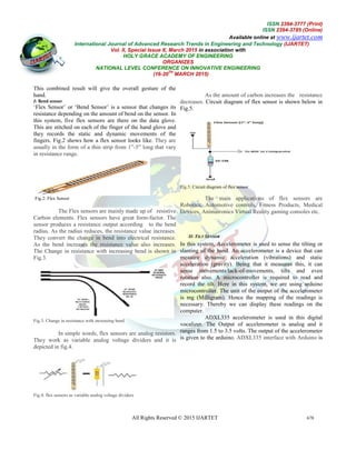
Block diagram of the whole system is shown Fig.1. The
system consists of:
Data Glove
Tilt Detection
Bend Detection
Adriano Board
Audio Processor
LCD Display
Fig.1: Block Diagram of the System
Digital glove is consisted of two sensors. They are
flex sensors and accelerometer as tilt sensor. The tilt
detection module and the bend detection
output of the accelerometer and flex sensor respectively
combinations of these results will lead to the generation of
some binary addresses; and those 8-bit addresses are directly
switched to the audio processor. For
address will be different. Audio processor processes it and
speaks. The data will be sent to the LCD which displays the
word corresponding word.
IV. SYSTEM DESCRIPTION
A. Data Glove
Flex sensors and accelerometer as tilt sensors
which are placed on the data glove
accelerometer is detected by the tilt detection module, while
the output of the flex sensors is detected by the bend
detection module. The combination of these results of two
sensors is given to the arduino UNO for further operations.
ISSN 2394-3777 (Print)
ISSN 2394-3785 (Online)
Available online at www.ijartet.com
al of Advanced Research Trends in Engineering and Technology (IJARTET)
677
Nonspecific-User Hand
An Algorithm and its
is discussed in reference [15].
METHODOLOGY
ystem is shown Fig.1. The
Digital glove is consisted of two sensors. They are
flex sensors and accelerometer as tilt sensor. The tilt
the bend detection module detect the
output of the accelerometer and flex sensor respectively. The
lead to the generation of
bit addresses are directly
o processor. For each gesture, the binary
. Audio processor processes it and
The data will be sent to the LCD which displays the
SYSTEM DESCRIPTION
lex sensors and accelerometer as tilt sensors are the sensors
which are placed on the data glove. The output of the
accelerometer is detected by the tilt detection module, while
the output of the flex sensors is detected by the bend
detection module. The combination of these results of two
given to the arduino UNO for further operations.](https://image.slidesharecdn.com/7015cb6c-767d-40b7-afb1-70e997e8ef82-150617171034-lva1-app6891/85/delna-s-journal-2-320.jpg)
![International Journal of Advanced Research Trends in Engineering and Technology
Vol. II, Special Issue X, March 2015
HOLY GRACE ACADEMY OF ENGINEERING
NATIONAL LEVEL CONFERENCE ON INNOVATIVE ENGINEERING
All Rights Reserved © 2015 IJARTET
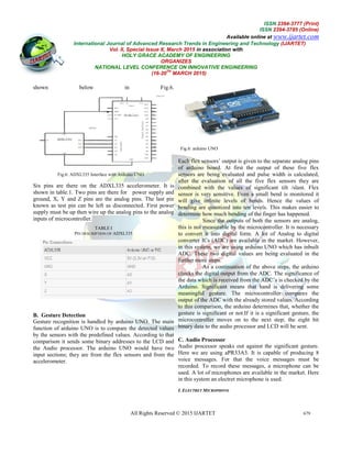
Fig.15:aPR33A3 Interface with Arduino UNO
Some particular allophones are allocated to each
word and for those allophones some addresses are defined in
audio processor IC. These 8 bit addresses are
aPR33A3 to speak those particular words
that it is necessary to know the 8 bit digital address
word or sentence. The microcontroller sends the
to aPR33A3. The address will locate the
word. The aPR33A3 gives an output signal and it can be
amplified to make it louder. The speaker takes the o
this amplifier as the input and it speaks the voice message
corresponding to the 8-bit addresses.
D. LCD Display
The audio processor gives a provision for the
communication of dumb with the normal people and with
the blind people as well. But the communication gap
between the dump people and the deaf
reduced with the help of audio processor IC
condition a display can be attached along with the audio
processor.
Fig.16: LCD Interface with Arduino UNO
JHD162A is the LCD module used here. JHD162A is a 16×2
LCD module based on the HD44780 driver from Hitachi.
The JHD162A has 16 pins and can be operated in 4
or 8-bit mode. The microcontroller has already
generated the 8 bit address bit and it is b
audio processor, the same address is being
ISSN
Available online at
al of Advanced Research Trends in Engineering and Technology
Vol. II, Special Issue X, March 2015 in association with
HOLY GRACE ACADEMY OF ENGINEERING
ORGANIZES
NATIONAL LEVEL CONFERENCE ON INNOVATIVE ENGINEERING
(16-20
TH
MARCH 2015)
All Rights Reserved © 2015 IJARTET
Some particular allophones are allocated to each
for those allophones some addresses are defined in
es are sent to the
s. The summary is
8 bit digital addresses of each
microcontroller sends these addresses
the allophone of the
output signal and it can be
amplified to make it louder. The speaker takes the output of
the voice messages
a provision for the
communication of dumb with the normal people and with
he communication gap
people cannot be
reduced with the help of audio processor IC. To avoid this
can be attached along with the audio
JHD162A is the LCD module used here. JHD162A is a 16×2
LCD module based on the HD44780 driver from Hitachi.
The JHD162A has 16 pins and can be operated in 4-bit mode
The microcontroller has already
generated the 8 bit address bit and it is being sent to the
address is being sent to the LCD
module. An eight bit address against each
is sent to LCD module. This eight bit address decides what
should be displayed on the LCD.
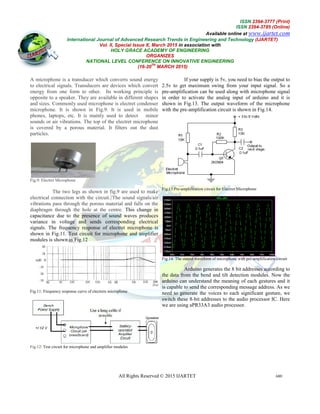
V. Overview of the System
The Fig.17 depicts the over view of the Digital Vocalizer.
Fig.17: An overview of the whole system
6. Conclusion and Future Enhancements
a detailed structure of a system is designed to make the
communication gap between dumb, blind
communities and their communication with the normal
people who can speak, see and talk
sign language is being by the dump communities used for
their communication. But these sign languages cannot be
used for the communication of dump communities with the
blind as well as normal people. Here we can use this Digital
Vocalizer which will generate voice and display according
to these signs. This display will help deaf communities to
reduce the communication gap also.
The future enhancements:
1. A provision for ZigBee standard for
Vocalizer”.
2. A new design with TTS256t
storage capacity.
3. Accurate monitoring of the static dynamic
movements involved in “Digital Vocalizer”.
4. A system with whole jacket, which could
capable of conveying the movements of animals.
5. The replacement of virtual reality application like
joy sticks with the “Digital Vocalizer” (Data
Glove).
VI. REFERENCES
[1] Kazunori Umeda Isao Furusawa and Shinya
Tanaka, “Recognition of Hand Gestures Using
Range Images”, Proceedings of the 1998 IEEW/RSJ
International Conference on intelligent Robots and
Systems Victoria, B.C., Canada October 1998, pp.
1727-1732
ISSN 2394-3777 (Print)
ISSN 2394-3785 (Online)
Available online at www.ijartet.com
al of Advanced Research Trends in Engineering and Technology (IJARTET)
681
against each significant gesture
is sent to LCD module. This eight bit address decides what
the System
17 depicts the over view of the Digital Vocalizer.
Enhancements This paper gives
system is designed to make the
communication gap between dumb, blind and deaf
communities and their communication with the normal
as less as possible. The
sign language is being by the dump communities used for
their communication. But these sign languages cannot be
of dump communities with the
blind as well as normal people. Here we can use this Digital
Vocalizer which will generate voice and display according
This display will help deaf communities to
A provision for ZigBee standard for “Digital
A new design with TTS256t to improve message
Accurate monitoring of the static dynamic
movements involved in “Digital Vocalizer”.
jacket, which could be
capable of conveying the movements of animals.
The replacement of virtual reality application like
joy sticks with the “Digital Vocalizer” (Data
Kazunori Umeda Isao Furusawa and Shinya
d Gestures Using
Proceedings of the 1998 IEEW/RSJ
International Conference on intelligent Robots and
., Canada October 1998, pp.](https://image.slidesharecdn.com/7015cb6c-767d-40b7-afb1-70e997e8ef82-150617171034-lva1-app6891/85/delna-s-journal-6-320.jpg)
![International Journal of Advanced Research Trends in Engineering and Technology
Vol. II, Special Issue X, March 2015
HOLY GRACE ACADEMY OF ENGINEERING
NATIONAL LEVEL CONFERENCE ON INNOVATIVE ENGINEERING
All Rights Reserved © 2015 IJARTET
[2] Srinivas Gutta, Jeffrey Huang, Ibrahim F. Imam,
and Harry Wechsler, “Face and Hand Gesture
Recognition Using Hybrid Classifiers”, ISBN: 0
8186-7713-9/96, pp.164-169
[3] Jean-Christophe Lementec and Peter Bajcsy,
“Recognition of Am Gestures Using Multiple
Orientation Sensors: Gesture Classification”,
IEEE Intelligent Transportation Systems Conference
Washington, D.C., USA, October 34, 2004, pp.965
970
[4] Microcontroller and Sensors Based Gesture Vocalizer
Proceedings of the 7th WSEAS International Conference on
SIGNAL PROCESSING, ROBOTICS and AUTOMATION
(ISPRA '08), University of Cambridge, UK, February 20
2008
[5] Sushmita Mitra and Tinku Acharya,”Gesture
Recognition: A Survey”, IEEE TRANSACTIONS ON
SYSTEMS, MAN, AND CYBERNETICS
APPLICATIONS AND REVIEWS, VOL. 37, NO. 3,
MAY 2007, pp. 311-324
[6] Recognition of a Hand-Gesture Based on
Self-organization Using a Data Glove, 0-7803
~/99/$10.080 1999 IEEE
[7] Sanshzar Kettebekov, Mohammed Yeasin and
Rajeev Sharma, “Improving Continuous Gesture
Recognition with Spoken Prosody”, Proceedings of the
2003 IEEE Computer Society Conference o
Vision and Pattern Recognition (CVPR’03),
1063-6919/03, pp.1-6
[8] Masumi Ishikawa and Hiroko Matsumura,
“Recognition of a Hand-Gesture Based on Selforganization
Using a Data Glove”, ISBN # 0-7803-
5871-6/99, pp. 739-745
[9] Hand Gesture Recognition Using Accelerometer
Sensor for Traffic Light Control System.
Shirke Swapnali, Student of ENTC Dept., SKNCOE,PUNE
Pune,India
[10] Gloved and Free Hand Tracking based Hand Gesture
Recognition,
978-1-4673-5250-5/13/$31.00 ©2013 IEEE
[11] Toshiyuki Kirishima, Kosuke Sato and Kunihiro
Chihara, “Real-Time Gesture Recognition by Learning
and Selective Control of Visual Interest Points”,
TRANSACTIONS ON PATTERN ANALYSIS AND
MACHINE INTELLIGENCE, VOL. 27, NO. 3,
MARCH 2005, pp. 351-364
[12] Attila Licsár and Tamás Szirány, “Dynamic
Training of Hand Gesture Recognition System”,
Proceedings of the 17th International Conference on
Pattern Recognition (ICPR’04), ISBN # 1051
4651/04,
[13] A Method of Hand Gesture Recognition based on
Multiple Sensors, Fan Wei, Chen Xiang, Wang Wen
Xu ,Yang Ji-hai,978-1-4244-4713-8/10/$25.00 ©2010 IEEE
[14] Nonspecific-User Hand Gesture Recognition By
Using MEMS Accelerometer, Jayaraman D
Student Member of IEEE
ISSN
Available online at
al of Advanced Research Trends in Engineering and Technology
Vol. II, Special Issue X, March 2015 in association with
HOLY GRACE ACADEMY OF ENGINEERING
ORGANIZES
NATIONAL LEVEL CONFERENCE ON INNOVATIVE ENGINEERING
(16-20
TH
MARCH 2015)
All Rights Reserved © 2015 IJARTET
Srinivas Gutta, Jeffrey Huang, Ibrahim F. Imam,
Hand Gesture
Recognition Using Hybrid Classifiers”, ISBN: 0-
Christophe Lementec and Peter Bajcsy,
“Recognition of Am Gestures Using Multiple
Orientation Sensors: Gesture Classification”, 2004
Systems Conference
USA, October 34, 2004, pp.965-
Microcontroller and Sensors Based Gesture Vocalizer
Proceedings of the 7th WSEAS International Conference on
SIGNAL PROCESSING, ROBOTICS and AUTOMATION
ridge, UK, February 20-22,
Sushmita Mitra and Tinku Acharya,”Gesture
IEEE TRANSACTIONS ON
SYSTEMS, MAN, AND CYBERNETICS—PART C:
VOL. 37, NO. 3,
7803-5871-
Sanshzar Kettebekov, Mohammed Yeasin and
Rajeev Sharma, “Improving Continuous Gesture
”, Proceedings of the
2003 IEEE Computer Society Conference on Computer
Vision and Pattern Recognition (CVPR’03), ISBN #
Masumi Ishikawa and Hiroko Matsumura,
Gesture Based on Selforganization
ion Using Accelerometer
Shirke Swapnali, Student of ENTC Dept., SKNCOE,PUNE
Gloved and Free Hand Tracking based Hand Gesture
5/13/$31.00 ©2013 IEEE, ICETACS 2013
Kirishima, Kosuke Sato and Kunihiro
Time Gesture Recognition by Learning
and Selective Control of Visual Interest Points”, IEEE
TRANSACTIONS ON PATTERN ANALYSIS AND
VOL. 27, NO. 3,
and Tamás Szirány, “Dynamic
Training of Hand Gesture Recognition System”,
Proceedings of the 17th International Conference on
ISBN # 1051-
A Method of Hand Gesture Recognition based on
Xiang, Wang Wen-hui, Zhang
8/10/$25.00 ©2010 IEEE
User Hand Gesture Recognition By
Jayaraman D
Department of ECE,ICICES2014 -
Chennai, Tamil Nadu, India
[15] lianfeng Liu, Zhigeng Pan, Xiangcheng Li "An Accelerometer
Based
Gesture Recognition Algorithm and its Application for 3D
Interaction";
ComSIS Vol. 7, No. I, Special Issue, February 2010.
ISSN 2394-3777 (Print)
ISSN 2394-3785 (Online)
Available online at www.ijartet.com
al of Advanced Research Trends in Engineering and Technology (IJARTET)
682
S.A.Engineering College,
lianfeng Liu, Zhigeng Pan, Xiangcheng Li "An Accelerometer-
Gesture Recognition Algorithm and its Application for 3D
ComSIS Vol. 7, No. I, Special Issue, February 2010.](https://image.slidesharecdn.com/7015cb6c-767d-40b7-afb1-70e997e8ef82-150617171034-lva1-app6891/85/delna-s-journal-7-320.jpg)

This document describes a digital vocalizer system that uses a data glove with flex sensors and an accelerometer to detect hand gestures. The sensors detect finger bending and hand tilt/position. The Arduino UNO microcontroller converts these detected gestures into corresponding audio words or visual text displayed on an LCD screen. This system aims to help reduce communication barriers between deaf/mute/blind communities and others by translating gestures into audio and visual outputs.