This document describes the construction of the world's largest lake-source cooling system in Toronto, Canada. It details:
- The $175 million deep lake water cooling system, which involves pumping cold water from Lake Ontario to cool over 65 megawatts of buildings in downtown Toronto.
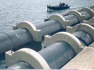
- Construction started in June 2002 and was completed in summer 2004. It included building an energy transfer station, tunneling a distribution loop underground, fabricating and deploying 15km of intake piping 5km into Lake Ontario.
- The system provides environmental benefits by reducing greenhouse gas emissions equivalent to taking 15,000 cars off the road annually and displacing 40,000kg of CFCs. It is a sustainable solution that


![Case study plant4 putrajaya[arul hisham]](https://cdn.slidesharecdn.com/ss_thumbnails/casestudyplant4putrajayaarulhisham-140831224159-phpapp01-thumbnail.jpg?width=640&height=640&fit=bounds)


