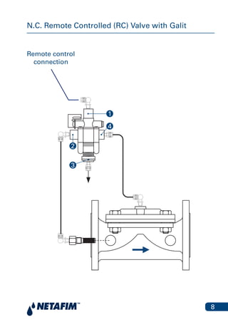
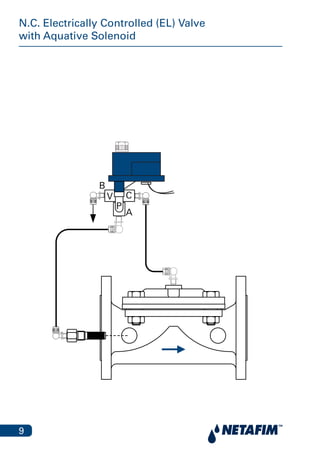
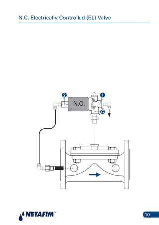
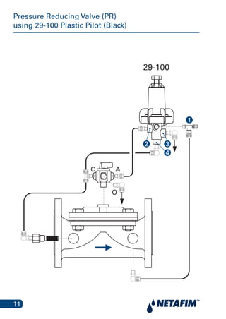
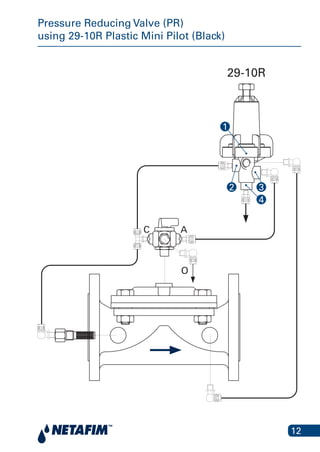
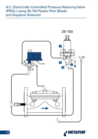
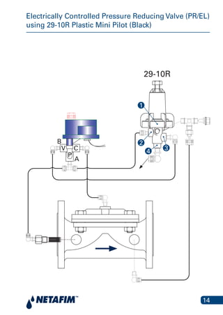
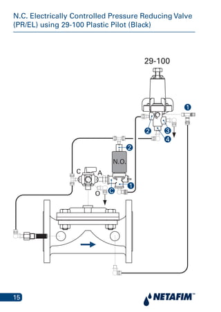
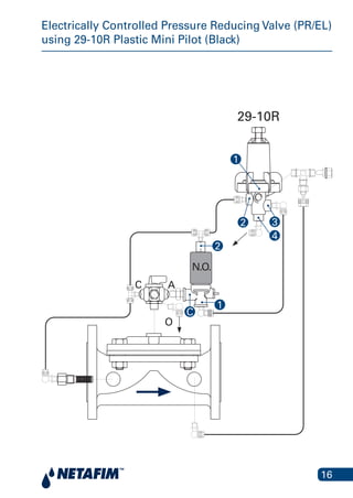
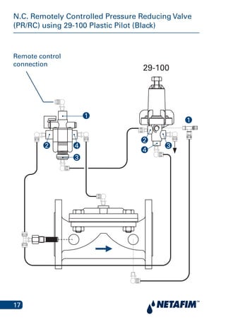
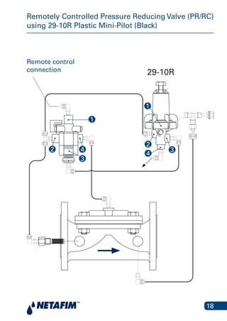
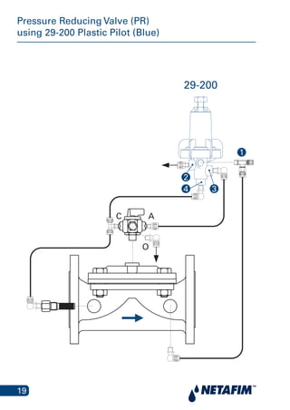
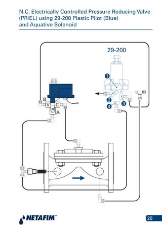
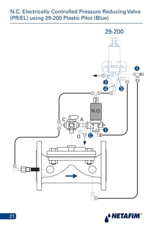
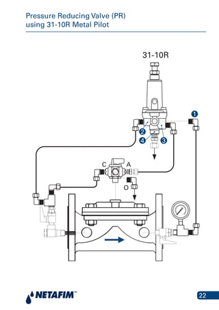
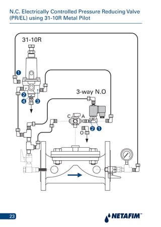
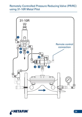
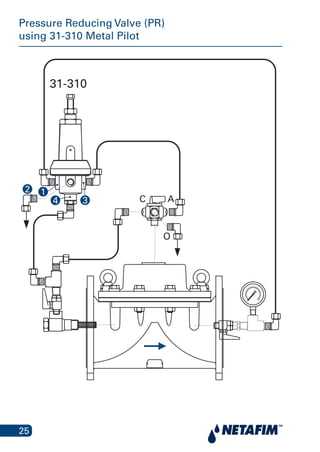
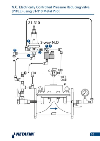
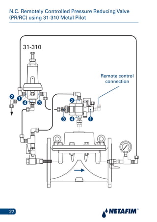
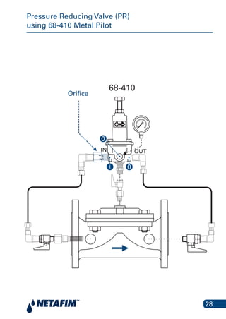
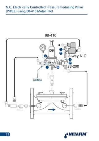
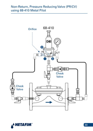
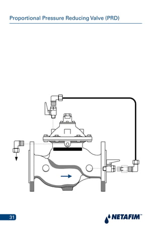
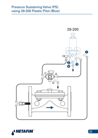
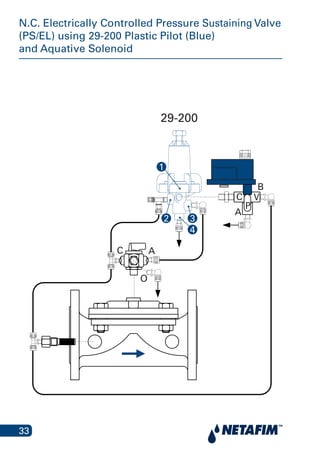
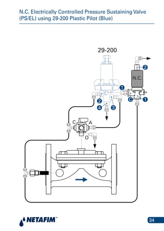
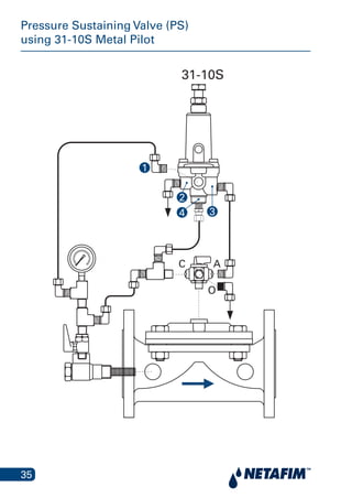
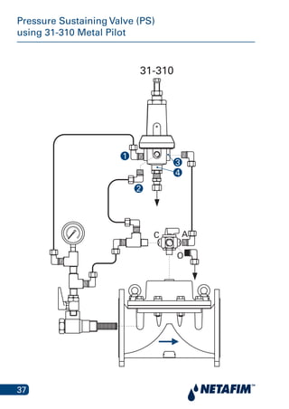
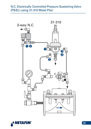
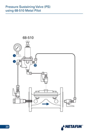
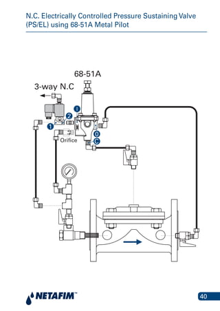
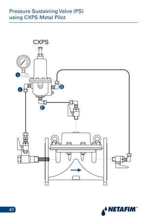
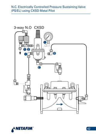
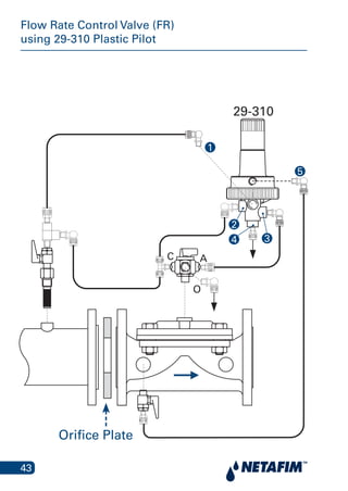
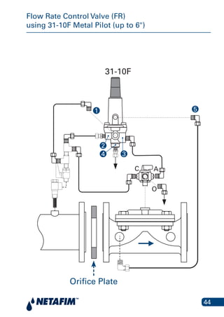
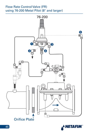
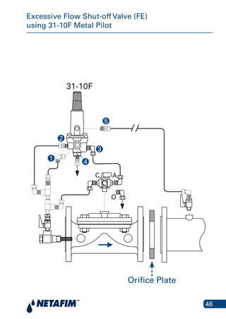
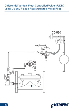
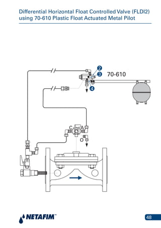
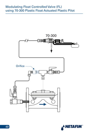
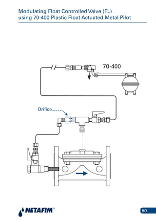
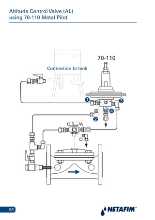
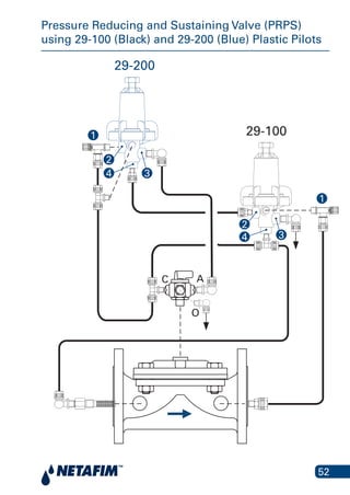
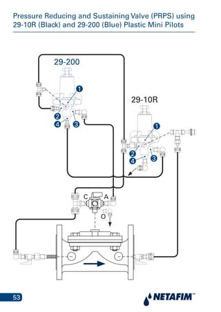
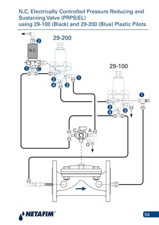
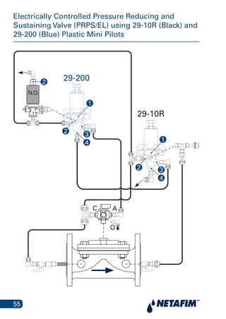
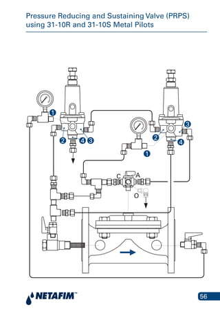
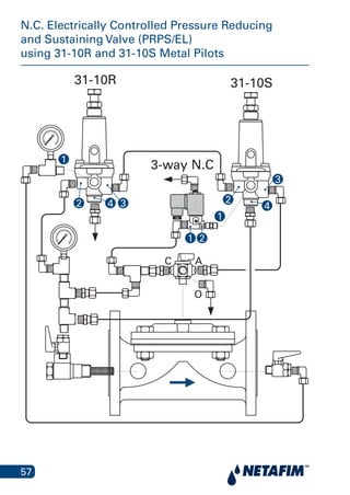
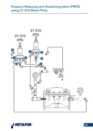
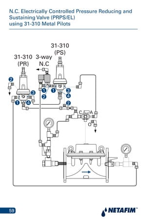
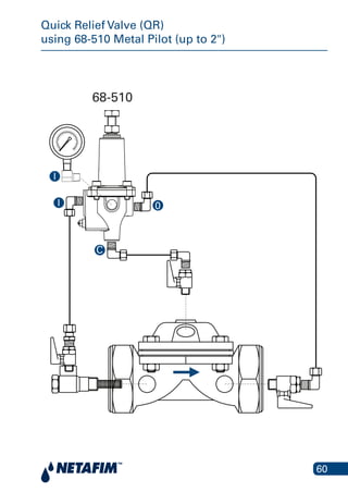
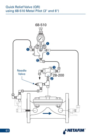
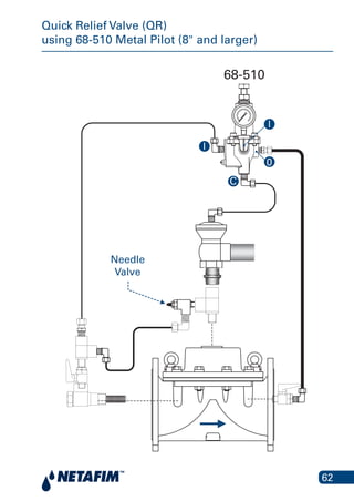
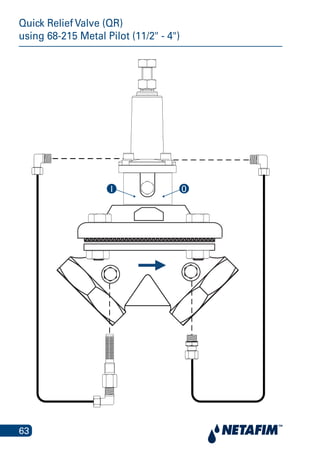
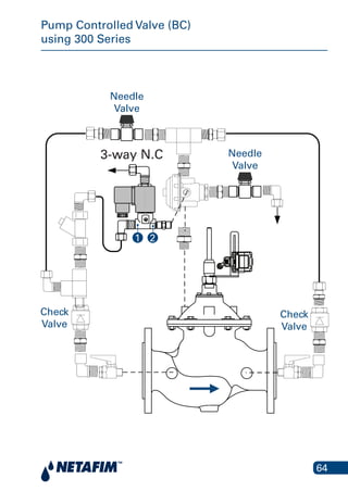
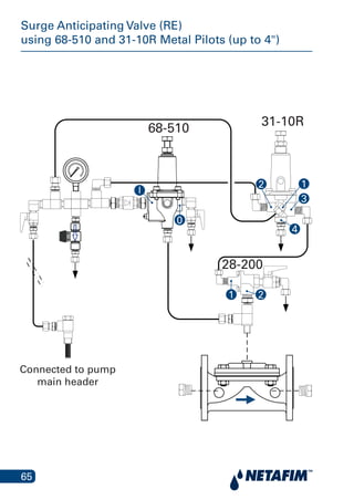
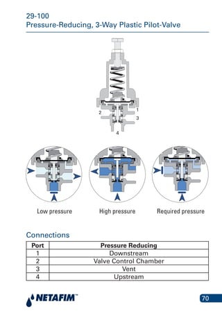
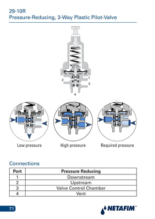
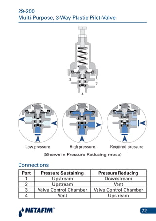
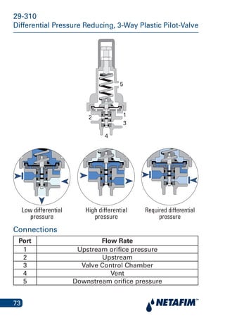
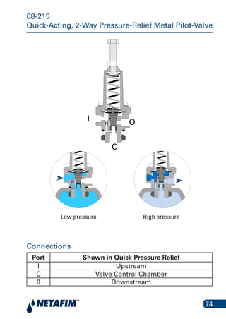
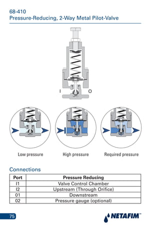
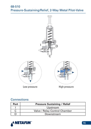
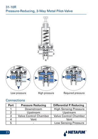
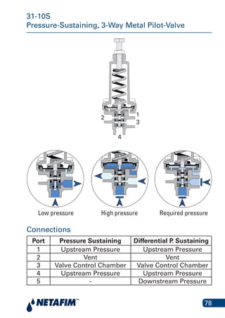
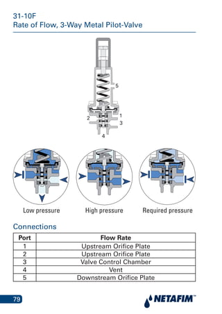
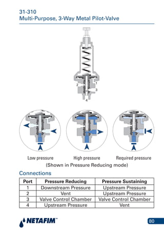
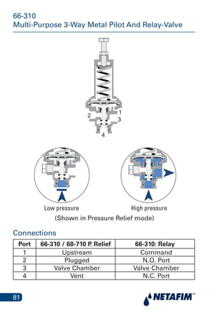
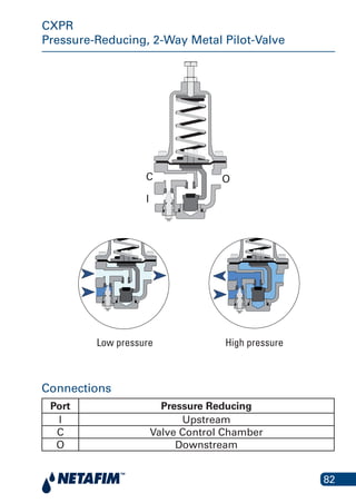
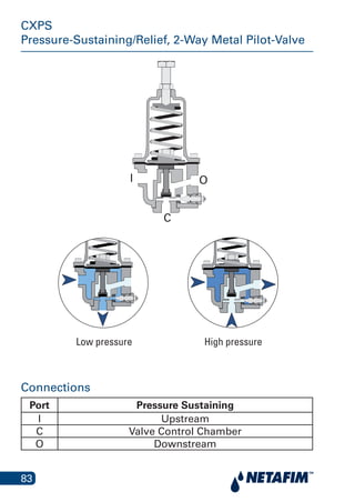
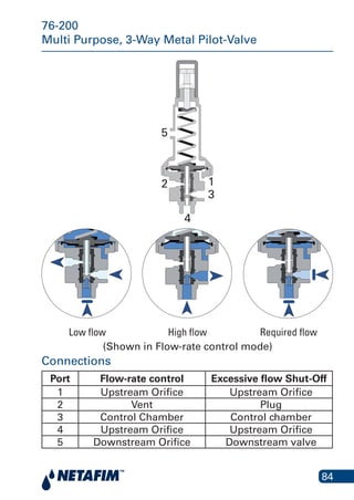
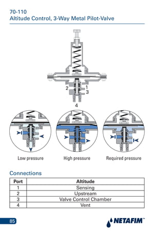
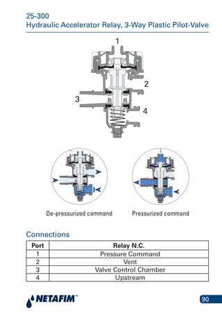
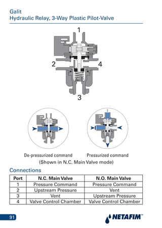
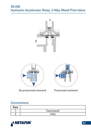
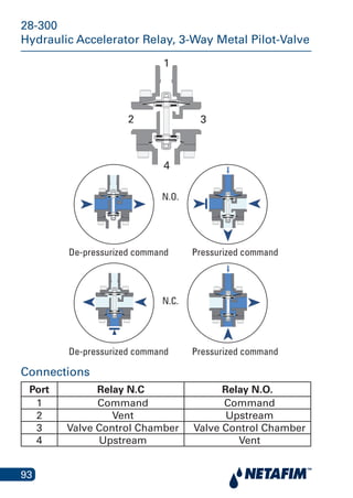
Connection
Diagrams
2017
2
Contents
N.C. Remote Controlled (RC) Valve with Galit 8
N.C. Electrically Controlled (EL) Valve with Aquative Solenoid 9
N.C. Electrically Controlled (EL) Valve 10
Pressure Reducing Valve (PR)
using 29-100 Plastic Pilot (Black) 11
Pressure Reducing Valve (PR)
using 29-10R Plastic Mini Pilot (Black) 12
N.C. Electrically Controlled Pressure Reducing Valve (PR/EL)
using 29-100 Plastic Pilot (Black) and Aquative Solenoid 13
Electrically Controlled Pressure Reducing Valve (PR/EL)
using 29-10R Plastic Mini Pilot (Black) 14
N.C. Electrically Controlled Pressure Reducing Valve (PR/EL)
using 29-100 Plastic Pilot (Black) 15
Electrically Controlled Pressure Reducing Valve (PR/EL)
using 29-10R Plastic Mini Pilot (Black) 16
N.C. Remotely Controlled Pressure Reducing Valve (PR/RC)
using 29-100 Plastic Pilot (Black) 17
Remotely Controlled Pressure Reducing Valve (PR/RC)
using 29-10R Plastic Mini-Pilot (Black) 18
Pressure Reducing Valve (PR)
using 29-200 Plastic Pilot (Blue) 19
N.C. Electrically Controlled Pressure Reducing Valve (PR/EL)
using 29-200 Plastic Pilot (Blue) and Aquative Solenoid 20
N.C. Electrically Controlled Pressure Reducing Valve (PR/EL)
using 29-200 Plastic Pilot (Blue) 21
Pressure Reducing Valve (PR)
using 31-10R Metal Pilot 22
N.C. Electrically Controlled Pressure Reducing Valve (PR/EL)
using 31-10R Metal Pilot 23
Remotely Controlled Pressure Reducing Valve (PR/RC)
using 31-10R Metal Pilot 24
3
Contents
Pressure Reducing Valve (PR)
using 31-310 Metal Pilot 25
N.C. Electrically Controlled Pressure Reducing Valve (PR/EL)
using 31-310 Metal Pilot 26
N.C. Remotely Controlled Pressure Reducing Valve (PR/RC)
using 31-310 Metal Pilot 27
Pressure Reducing Valve (PR)
using 68-410 Metal Pilot 28
N.C. Electrically Controlled Pressure Reducing Valve (PR/EL)
using 68-410 Metal Pilot 29
Non-Return, Pressure Reducing Valve (PR/CV)
using 68-410 Metal Pilot 30
Proportional Pressure Reducing Valve (PRD) 31
Pressure Sustaining Valve (PS)
using 29-200 Plastic Pilot (Blue) 32
N.C. Electrically Controlled Pressure Sustaining Valve (PS/EL)
using 29-200 Plastic Pilot (Blue) and Aquative Solenoid 33
N.C. Electrically Controlled Pressure Sustaining Valve (PS/EL)
using 29-200 Plastic Pilot (Blue) 34
Pressure Sustaining Valve (PS)
using 31-10S Metal Pilot 35
N.C. Electrically Controlled Pressure Sustaining Valve (PS/EL)
using 31-10S Metal Pilot 36
Pressure Sustaining Valve (PS)
using 31-310 Metal Pilot 37
N.C. Electrically Controlled Pressure Sustaining Valve (PS/EL)
using 31-310 Metal Pilot 38
Pressure Sustaining Valve (PS)
using 68-510 Metal Pilot 39
N.C. Electrically Controlled Pressure Sustaining Valve (PS/EL)
using 68-51A Metal Pilot 40
4
Contents
Pressure Sustaining Valve (PS)
using CXPS Metal Pilot 41
N.C. Electrically Controlled Pressure Sustaining Valve (PS/EL)
using CXSD Metal Pilot 42
Flow Rate Control Valve (FR)
using 29-310 Plastic Pilot 43
Flow Rate Control Valve (FR)
using 31-10F Metal Pilot (up to 6") 44
Flow Rate Control Valve (FR)
using 76-200 Metal Pilot (8" and larger) 45
Excessive Flow Shut-off Valve (FE)
using 31-10F Metal Pilot 46
Differential Vertical Float Controlled Valve (FLDI1)
using 70-550 Plastic Float Actuated Metal Pilot 47
Differential Horizontal Float Controlled Valve (FLDI2)
using 70-610 Plastic Float Actuated Metal Pilot 48
Modulating Float Controlled Valve (FL)
using 70-300 Plastic Float Actuated Plastic Pilot 49
Modulating Float Controlled Valve (FL)
using 70-400 Plastic Float Actuated Metal Pilot 50
Altitude Control Valve (AL)
using 70-110 Metal Pilot 51
Pressure Reducing and Sustaining Valve (PRPS)
using 29-100 (Black) and 29-200 (Blue) Plastic Pilots 52
N.C. Electrically Controlled Pressure Reducing
and Sustaining Valve (PRPS/EL)
using 29-100 (Black) and 29-200 (Blue) Plastic Pilots 53
N.C. Electrically Controlled Pressure Reducing and
Sustaining Valve (PRPS/EL)
using 29-100 (Black) and 29-200 (Blue) Plastic Pilots 54
5
Contents
Electrically Controlled Pressure Reducing
and Sustaining Valve (PRPS/EL)
using 29-10R (Black) and 29-200 (Blue) Plastic Mini Pilots 55
Pressure Reducing and Sustaining Valve (PRPS)
using 31-10R and 31-10S Metal Pilots 56
N.C. Electrically Controlled Pressure Reducing and Sustaining
Valve (PRPS/EL)
using 31-10R and 31-10S Metal Pilots 57
Pressure Reducing and Sustaining Valve (PRPS)
using 31-310 Metal Pilots 58
N.C. Electrically Controlled Pressure Reducing and Sustaining
Valve (PRPS/EL)
using 31-310 Metal Pilots 59
Quick Relief Valve (QR)
using 68-510 Metal Pilot (up to 2") 60
Quick Relief Valve (QR)
using 68-510 Metal Pilot (3" and 6") 61
Quick Relief Valve (QR)
using 68-510 Metal Pilot (8" and larger) 62
Quick Relief Valve (QR)
using 68-215 Metal Pilot (11
/2" - 4") 63
Pump Controlled Valve (BC)
using 300 Series 64
Surge Anticipating Valve (RE)
using 68-510 and 31-10R Metal Pilots (up to 4") 65
Control Accessories - General 66
Solenoid Aquative
3-Way Solenoid 68
Solenoid Gemsol
3-Way Solenoid 69
6
Contents
29-100
Pressure-Reducing, 3-Way Plastic Pilot-Valve 70
29-10R
Pressure-Reducing, 3-Way Plastic Pilot-Valve 71
29-200
Multi-Purpose, 3-Way Plastic Pilot-Valve 72
29-310
Differential Pressure Reducing, 3-Way Plastic Pilot-Valve 73
68-215
Quick-Acting, 2-Way Pressure-Relief Metal Pilot-Valve 74
68-410
Pressure-Reducing, 2-Way Metal Pilot-Valve 75
68-510
Pressure-Sustaining/Relief, 2-Way Metal Pilot-Valve 76
31-10R
Pressure-Reducing, 3-Way Metal Pilot-Valve 77
31-10S
Pressure-Sustaining, 3-Way Metal Pilot-Valve 78
31-10F
Rate of Flow, 3-Way Metal Pilot-Valve 79
31-310
Multi-Purpose, 3-Way Metal Pilot-Valve 80
66-310
Multi-Purpose 3-Way Metal Pilot And Relay-Valve 81
CXPR
Pressure-Reducing, 2-Way Metal Pilot-Valve 82
CXPS
Pressure-Sustaining/Relief, 2-Way Metal Pilot-Valve 83
76-200
Multi Purpose, 3-Way Metal Pilot-Valve 84
70-110
Altitude Control, 3-Way Metal Pilot-Valve 85
7
Contents
70-300
Modulating, 2-Way Float Actuated Plastic Pilot-Valve 86
70-400
Modulating, 2-Way Float Actuated Metal Pilot-Valve 87
70-550
Differential, 3 Or 4-Way Vertical Float Actuated Metal Pilot-Valve 88
70-610
Differential, 3-Way Horizontal Float Actuated Metal Pilot-Valve 89
25-300
Hydraulic Accelerator Relay, 3-Way Plastic Pilot-Valve 90
Galit
Hydraulic Relay, 3-Way Plastic Pilot-Valve 91
28-200
Hydraulic Accelerator Relay, 2-Way Metal Pilot-Valve 92
28-300
Hydraulic Accelerator Relay, 3-Way Metal Pilot-Valve 93
Hydraulic Equations 94
Units Conversion 95
8
N.C. Remote Controlled (RC) Valve with Galit
Remote control
connection
Remote control
connection
4
3
2
1
9
N.C. Electrically Controlled (EL) Valve
with Aquative Solenoid
A
B
CV
P
10
N.C. Electrically Controlled (EL) ValveValve
N.O.
2 1
C
11
Pressure Reducing Valve (PR)
using 29-100 Plastic Pilot (Black)
ure R educing Valve (PR ) using 29-1
Plastic Mini Pilot (Black)
A
29-100
C
O
4
32
1
12
Pressure Reducing Valve (PR)
using 29-10R Plastic Mini Pilot (Black)
29-10R
AC
O
4
32
1
13
29-100
N.C. Electrically Controlled Pressure Reducing Valve
(PR/EL) using 29-100 Plastic Pilot (Black)
and Aquative Solenoid
1
2
3
4
A
B
C
P
V
14
Electrically Controlled Pressure Reducing Valve (PR/EL)
using 29-10R Plastic Mini Pilot (Black)
Electrically Controlled Pressure Reducing Valve (PR/EL) using 29-
10R Plastic Mini Pilot (Black)
29-10R
A
B
C
P
V
1
2
34
15
N.C. Electrically Controlled Pressure Reducing Valve
(PR/EL) using 29-100 Plastic Pilot (Black)
ally Controlled Pressure Reducing Valv
29-100 Plastic Mini Pilot (Black
AC
O
N.O.
29-100
4
32
1
2
1
C
16
29-10R
Electrically Controlled Pressure Reducing Valve (PR/EL)
using 29-10R Plastic Mini Pilot (Black)
Electrically Controlled Pressure Reducing Valve (PR/EL) using 29-
10R Plastic Mini Pilot (Black)
N.O.
AC
O
1
C
2
4
32
1
17
N.C. Remotely Controlled Pressure Reducing Valve
(PR/RC) using 29-100 Plastic Pilot (Black)
lled Pressure Reducing Valve (PR/R
9-100 Plastic Mini-Pilot (Black)
Remote control
connection
29-100
4
4 3
3
2
2
1
1
18
29-10R
Remotely Controlled Pressure Reducing Valve (PR/RC)
using 29-10R Plastic Mini-Pilot (Black)
Remotely Controlled Pressure Reducing Valve (PR/RC) using 29-10R Plastic Mini-
Pilot (Black)
Remote control
connection
4
3
2
1
4
3
2
1
19
Pressure Reducing Valve (PR)
using 29-200 Plastic Pilot (Blue)
Plastic Mini Pilot (Blue)
29-200
AC
O
4 3
2
1
20
N.C. Electrically Controlled Pressure Reducing Valve
(PR/EL) using 29-200 Plastic Pilot (Blue)
and Aquative Solenoid
29-200
A
B
CV
P
3
2
1
4
21
N.C. Electrically Controlled Pressure Reducing Valve
(PR/EL) using 29-200 Plastic Pilot (Blue)
sing 29-200 Plastic Mini Pilot (Blue)
29-200
AC
O
2
N.O.
4 3
2
1
1
C
22
Pressure Reducing Valve (PR)
using 31-10R Metal Pilot
essure Reducing Valve (PR) using 3
Mini-Pilot
31-10R
A
O
C
4 3
2
1
23
N.C. Electrically Controlled Pressure Reducing Valve
(PR/EL) using 31-10R Metal Pilot
ed Pressure Reducing Valve (PR/EL
31-10R Metal Mini-Pilot
31-10R
3-way N.O
A
O
C
4 3
2
2
1
1
24
Remotely Controlled Pressure Reducing Valve (PR/RC)
using 31-10R Metal Pilot
31-10R Metal Mini-Pilot
Remote control
connection
31-10R
4 3
2
1
43
2
1
25
Pressure Reducing Valve (PR)
using 31-310 Metal Pilot
Pilot
31-310
A
O
C4 3
12
26
N.C. Electrically Controlled Pressure Reducing Valve
(PR/EL) using 31-310 Metal Pilot
31-310
A
O
C
4
3
2
1
1
3-way N.O
2
27
N.C. Remotely Controlled Pressure Reducing Valve
(PR/RC) using 31-310 Metal Pilot
motely Controlled Pressure Reducing
31-310 Metal Pilot
Remote control
connection
31-310
4
2
13
4 3
2 1
28
Pressure Reducing Valve (PR)
using 68-410 Metal Pilot
sure Reducing Valve (PR) using 68-4
Pilot
Orifice
68-410
IN OUT
0
I 0
29
N.C. Electrically Controlled Pressure Reducing Valve
(PR/EL) using 68-410 Metal Pilot
ntrolled Pressure Reducing Valve (PR
68-410 Metal Mini-Pilot
Orifice
68-410
IN
IN
OUT
0
I 0
2
2
1
1
3-way N.O
28-200
30
Non-Return, Pressure Reducing Valve (PR/CV)
using 68-410 Metal Pilot
Orifice 68-410
IN OUT
0
I 0
Check
Valve
Check
Valve
31
Proportional Pressure Reducing Valve (PRD)
32
Pressure Sustaining Valve (PS)
using 29-200 Plastic Pilot (Blue)
29-200
A
O
C
4
3
2
1
33
29-20029-200
1
N.C. Electrically Controlled Pressure Sustaining Valve
(PS/EL) using 29-200 Plastic Pilot (Blue)
and Aquative Solenoid
2 3
4
A
A
B
V
P
C
C
O
34
N.C. Electrically Controlled Pressure Sustaining Valve
(PS/EL) using 29-200 Plastic Pilot (Blue)
29-200
A
O
C
N.C.
4 3
2
2
1
1C
35
Pressure Sustaining Valve (PS)
using 31-10S Metal Pilot
ressure Sustaining Valve (PS) using
Metal Mini Pilot
31-10S
A
O
C
4 3
2
1
36
N.C. Electrically Controlled Pressure Sustaining Valve
(PS/EL) using 31-10S Metal Pilot
(PS/EL) using 31-10S Metal Mi
3-way N.C 31-10S
A
O
C
4 3
2
1
21
37
Pressure Sustaining Valve (PS)
using 31-310 Metal Pilot
essure Sustaining Valve (PS) using 3
Metal Pilot
31-310
A
O
C
4
3
2
1
38
N.C. Electrically Controlled Pressure Sustaining Valve
(PS/EL) using 31-310 Metal Pilot
Electrically Controlled Pressure Susta
(PS/EL) using 31-310 Metal P
31-310
A
O
C
21
4
3
2
1
3-way N.C
39
Pressure Sustaining Valve (PS)
using 68-510 Metal Pilotssure Sustaining Valve (PS) using 6
Metal Mini-Pilot
68-510
I
0
I
40
N.C. Electrically Controlled Pressure Sustaining Valve
(PS/EL) using 68-51A Metal Pilot
68-51A
Orifice
I
3-way N.C
C
2
1
0
41
Pressure Sustaining Valve (PS)
using CXPS Metal Pilot
CXPS
0
I
I
C
42
N.C. Electrically Controlled Pressure Sustaining Valve
(PS/EL) using CXSD Metal Pilot
CXSD
0I
I
21
3-way N.O
C
43
Flow Rate Control Valve (FR)
using 29-310 Plastic Pilot
ate Control Valve (FR ) using 29-310
Mini-Pilot
29-310
A
O
C
4 3
2
1
5
Orifice Plate
44
Flow Rate Control Valve (FR)
using 31-10F Metal Pilot (up to 6")
Rate Control Valve (FR) using 31-10
Mini-Pilot
31-10F
A
O
C
4 3
2
1 5
Orifice Plate
45
Flow Rate Control Valve (FR)
using 76-200 Metal Pilot (8" and larger)
76-200
A
O
C
4
3
2
1
5
Orifice Plate
46
Excessive Flow Shut-off Valve (FE)
using 31-10F Metal Pilot
sive Flow Shut-off Valve (FE) using
Metal Mini-Pilot
31-10F
A
O
C
3
2
1
5
4
Orifice Plate
47
Differential Vertical Float Controlled Valve (FLDI1)
using 70-550 Plastic Float Actuated Metal Pilot
a
Actuated Pilot
70-550
A
O
VP
B
T
C
48
Differential Horizontal Float Controlled Valve (FLDI2)
using 70-610 Plastic Float Actuated Metal Pilot
al Float Controlled Valve (FLDI2) using 70
Actuated Pilot
70-610
A
O
C
3
2
4
49
Modulating Float Controlled Valve (FL)
using 70-300 Plastic Float Actuated Plastic Pilot
Orifice
70-300
50
Modulating Float Controlled Valve (FL)
using 70-400 Plastic Float Actuated Metal Pilot
ntrolled Valve (FL) using 70-400 Floa
Orifice
70-400
51
Altitude Control Valve (AL)
using 70-110 Metal Pilot
ude Control Valve (AL) using 70-110
Pilot
Connection to tank
70-110
A
O
C
4
31
2
52
29-100 (Black) and 29-200 (Blue) Plast
Mini Pilots
29-200
29-100
A
O
C
4 3
1
2
4
1
2
3
Pressure Reducing and Sustaining Valve (PRPS)
using 29-100 (Black) and 29-200 (Blue) Plastic Pilots
53
Pilots
29-10R
29-200
Pressure Reducing and Sustaining Valve (PRPS) using
29-10R (Black) and 29-200 (Blue) Plastic Mini Pilots
A
O
C
4 3
2
14 3
2
1
54
N.C. Electrically Controlled Pressure Reducing and
Sustaining Valve (PRPS/EL)
using 29-100 (Black) and 29-200 (Blue) Plastic Pilots
Sustaining Valve (PRPS/EL) using 29-100
and 29-200 (Blue) Plastic Mini Pilot
29-100
29-200
N.C.
A
O
C
4 3
2
2
1
1
4
1
3
2
C
55
Electrically Controlled Pressure Reducing and
Sustaining Valve (PRPS/EL) using 29-10R (Black) and
29-200 (Blue) Plastic Mini Pilots
29-200
29-10R
A
O
C
N.O.
2
1
4
3
2
1
4
3
2
C
1
56
Pressure Reducing and Sustaining Valve (PRPS)
using 31-10R and 31-10S Metal Pilots
ssure R educing and S ustaining Valve
using 31-10R and 31-10S Pilots
A
O
C
4 32
1
4
3
2
1
57
N.C. Electrically Controlled Pressure Reducing
and Sustaining Valve (PRPS/EL)
using 31-10R and 31-10S Metal Pilots
Controlled Pressure Reducing and Su
PRPS/EL) using 31-10R and 31-10S P
31-10S31-10R
A
O
C
4 32
1
4
3
2
2
1
1
3-way N.C
58
Pressure Reducing and Sustaining Valve (PRPS)
using 31-310 Metal Pilots
31-310
(PR)
31-310
(PS)
A
O
C
4
43
2
2
1
1 3
59
N.C. Electrically Controlled Pressure Reducing and
Sustaining Valve (PRPS/EL)
using 31-310 Metal Pilots
31-310
(PR)
31-310
(PS)
A
O
C
4
11
2
2
3
2
1
3-way
N.C
3
4
60
Quick Relief Valve (QR)
using 68-510 Metal Pilot (up to 2")
68-510
0
C
I
I
61
Quick Relief Valve (QR)
using 68-510 Metal Pilot (3" and 6")Relief Valve (QR) using 68-510 Pilot
Needle
Valve
68-510
28-200
0
I
I
C
2
1
62
Quick Relief Valve (QR)
using 68-510 Metal Pilot (8" and larger)
larger)
Needle
Valve
68-510
0
I
I
C
63
Quick Relief Valve (QR)
using 68-215 Metal Pilot (11/2" - 4")
0I
64
Pump Controlled Valve (BC)
using 300 Series
1 2
Needle
Valve
Needle
Valve
Check
Valve
Check
Valve
3-way N.C
65
I
Surge Anticipating Valve (RE)
using 68-510 and 31-10R Metal Pilots (up to 4")
31-10R
68-510
Connected to pump
main header
4
3
2
2
1
1
0
28-200
66
Pressure Reducing (PR):
The valve will regulate to maintain a set downstream
pressure, regardless of upstream pressure or flow
variations.
Should the downstream pressure fall below the
requested value, the valve will open fully.
Pressure Sustaining (PS):
The valve will maintain a steady, predetermined
pressure in the network, upstream of its location.
If the pressure falls below the set-pressure, the valve
closes drip tight.
3-way Pilot Valves:
Ports Marking:
S - Pressure sensing port
P - Port for connection of upstream pressure.
C - Command port, connected to the valve control
chamber.
V - Vent port. Through this port water are vented when
the valve opens.
Operating Principle:
CLOSE - Connects ports P to C thus letting the
upstream pressure into the valve bonnet.
OPEN - Connects ports C to V thus venting the
pressure in the valve bonnet.
LOCK - Keep the valve in the present position by
blocking all ports.
Control Accessories - General
67
2-way Pilot Valves:
Operating Principle:
Increases or decreases a drainage passage from the
valve control chamber to downstream. The inlet to the
chamber is via a fixed orifice or a regulated needle valve.
CLOSE - The drainage flow through the pilot is smaller
than the inlet flow.
OPEN - The drainage flow through the pilot is larger
than the inlet flow.
LOCK - The drainage flow through the pilot is equal to
the inlet flow.
3-way Manual Selector Valve:
A ball valve with one common (fixed)
port and three functional ports:
“CLOSE” - Connected to the upstream.
“OPEN” - Vented to the atmosphere.
“AUTO” - Connected to the command
port of the control device (pilot,
solenoid etc.).
Needle Valve / Orifice:
For flow limitation in the control
system and reduction of the response
speed of the main valve.
Shuttle Valve:
Tee shaped pressure selector -
selecting the higher pressure when
the valve is controlled by two pressure
sources.
68
Solenoid Aquative
3-Way Solenoid
A A"
ns from
NO Energized
B
NO De-energized
B
COM COM
ration 2
No De-energized
B
(vent)
No Energized
NC De-energized
Note:
NC/NO is refering to the Hydraulic valve
NC Energized
B
(vent)
A
(vent)
COM
(command)
COM
(command)
A (pressure)A (pressure)
B
(pressure)
B
(pressure)
COM
(command)
COM
(command)
A
(vent)
69
Converts electric pulses to an hydraulic
command
Ports Marking:
P - Pressure port. Connected to the 	
upstream pressure.
C - Connected to the control chamber
of the valve.
V - Pressure venting port.
Solenoid Gemsol
3-Way Solenoid
P
C
P
C V
V
C
V
C P
V
P
Normally
open
De-Energised
Normally
closed
Energised
De-Energised Energised
2
(2) (1)
1 C
(2) (1)
(2) (1) (2) (1)
70
29-100
Pressure-Reducing, 3-Way Plastic Pilot-Valve
4
1
2
3
Low pressure High pressure Required pressure
29-100
Connections
Port Pressure Reducing
1 Downstream
2 Valve Control Chamber
3 Vent
4 Upstream
Low pressure Required pressureHigh pressure
71
29-10R
Pressure-Reducing, 3-Way Plastic Pilot-Valve
64
29-100
4
1
2
3
29-10R
Pressure-Reducing, 3-Way Plastic Pilot-Valve
29-100
Low pressure Required pressureHigh pressureLow pressure Required pressureHigh pressure
Connections
Port Pressure Reducing
1 Downstream
2 Upstream
3 Valve Control Chamber
4 Vent
72
29-200
Multi-Purpose, 3-Way Plastic Pilot-Valve
Connections
Port Pressure Sustaining Pressure Reducing
1 Upstream Downstream
2 Upstream Vent
3 Valve Control Chamber Valve Control Chamber
4 Vent Upstream
4
1
2
3
Low pressure High pressure Required pressure
29-200
Low pressure
(Shown in Pressure Reducing mode)
Required pressureHigh pressure
73
29-310
Differential Pressure Reducing, 3-Way Plastic Pilot-Valve
12
3
4
5
Low pressure High pressure Required pressure
29-310
Connections
Port Flow Rate
1 Upstream orifice pressure
2 Upstream
3 Valve Control Chamber
4 Vent
5 Downstream orifice pressure
Required differential
pressure
High differential
pressure
Low differential
pressure
74
Connections
Port Shown in Quick Pressure Relief
I Upstream
C Valve Control Chamber
0 Downstream
68-215
Quick-Acting, 2-Way Pressure-Relief Metal Pilot-Valve
I O
C
68-215
–
Low pressure High pressure
‫ה‬‫ם‬‫ו‬‫ה‬‫ת‬‫א‬‫מ‬‫ה‬
‫ה‬‫ב‬‫ק‬‫ט‬‫ל‬‫ו‬‫ג‬
75
68-410
Pressure-Reducing, 2-Way Metal Pilot-Valve
Low pressure High pressure Required pressure
I O
Connections
Port Pressure Reducing
I1 Valve Control Chamber
I2 Upstream (Through Orifice)
01 Downstream
02 Pressure gauge (optional)
Low pressure Required pressureHigh pressure
76
68-510
Pressure-Sustaining/Relief, 2-Way Metal Pilot-Valve
I O
C
Low pressure High Pressure
Connections
Port Pressure Sustaining / Relief
I Upstream
C Valve / Relay Control Chamber
O Downstream
Low pressure High pressure
Low pressureHigh pressure
I O
C
Standard version
I O
C
Low pressHigh pressure
77
31-10R
Pressure-Reducing, 3-Way Metal Pilot-Valve
1
3
4
2
Low pressure High pressure Required pressure
PSIColorSpring number
22 - 175RED124
7 - 85GREEN130
Port
Downstream1
2
3
4
Upstream
Control chamber
Vent
Pressure reducing
31-10R
Connections
Port Pressure Reducing Differential P. Reducing
1 Downstream High Sensing Pressure
2 Upstream Upstream
3 Valve Control Chamber Valve Control Chamber
4 Vent Vent
5 - Low Sensing Pressure
Low pressure Required pressureHigh pressure
78
31-10S
Pressure-Sustaining, 3-Way Metal Pilot-Valve
1
3
4
2
Low pressure High pressure Required pressure
31-10S
Connections
Port Pressure Sustaining Differential P. Sustaining
1 Upstream Pressure Upstream Pressure
2 Vent Vent
3 Valve Control Chamber Valve Control Chamber
4 Upstream Pressure Upstream Pressure
5 - Downstream Pressure
Low pressure Required pressureHigh pressure
79
31-10F
Rate of Flow, 3-Way Metal Pilot-Valve
12
3
4
5
Low flow High flow Required flow
31-10F
Connections
Port Flow Rate
1 Upstream Orifice Plate
2 Upstream Orifice Plate
3 Valve Control Chamber
4 Vent
5 Downstream Orifice Plate
Low pressure Required pressureHigh pressure
80
31-310
Multi-Purpose, 3-Way Metal Pilot-Valve
1
3
4
2
z
Low pressure High pressure Required pressure
Connections
Port Pressure Reducing Pressure Sustaining
1 Downstream Pressure Upstream Pressure
2 Vent Upstream Pressure
3 Valve Control Chamber Valve Control Chamber
4 Upstream Pressure Vent
Low pressure Required pressureHigh pressure
z
z z
(Shown in Pressure Reducing mode)
81
66-310
Multi-Purpose 3-Way Metal Pilot And Relay-Valve
1
3
4
2
Normal pressure High pressure
Connections
Port 66-310 / 68-710 P. Relief 66-310: Relay
1 Upstream Command
2 Plugged N.O. Port
3 Valve Chamber Valve Chamber
4 Vent N.C. Port
Low pressure High pressure
(Shown in Pressure Relief mode)
82
CXPR
Pressure-Reducing, 2-Way Metal Pilot-Valve
Connections
Port Pressure Reducing
I Upstream
C Valve Control Chamber
O Downstream
OC
I
Low pressure High pressure RequiredLow pressure High pressure
83
CXPS
Pressure-Sustaining/Relief, 2-Way Metal Pilot-Valve
C
OI
Low pressure High pressureLow pressure High pressure
Connections
Port Pressure Sustaining
I Upstream
C Valve Control Chamber
O Downstream
84
76-200
Multi Purpose, 3-Way Metal Pilot-Valve
1
3
4
2
z
5
Low flow High flow Required flow
76-200
Connections
Port Flow-rate control Excessive flow Shut-Off
1 Upstream Orifice Upstream Orifice
2 Vent Plug
3 Control Chamber Control chamber
4 Upstream Orifice Upstream Orifice
5 Downstream Orifice Downstream valve
Low flow Required flowHigh flow
z
z z
(Shown in Flow-rate control mode)
85
70-110
Altitude Control, 3-Way Metal Pilot-Valve
W
H
2
4
1
3
Low pressure Required pressureHigh pressure
Connections
Port Altitude
1 Sensing
2 Upstream
3 Valve Control Chamber
4 Vent
86
70-300
Modulating, 2-Way Float Actuated Plastic Pilot-Valve450 mm
High level Low level
87
70-400
Modulating, 2-Way Float Actuated Metal Pilot-Valve
220mm
680 mm
Max. level Low level
88
70-550
Differential, 3 Or 4-WayVertical Float Actuated Metal Pilot-Valve
Max. level Min. level
Max. level
Min. level
Max. level
Min. level
Connections
Port Level control
P Upstream
T Valve Control Chamber
V Vent
B Plug*
89
70-610
Differential, 3-Way Horizontal Float Actuated Metal Pilot-Valve
Max. level Min. level
Max. level
Min. level
Max. level
Min. level
Connections
Port
2 Upstream
3 Valve Control Chamber
4 Vent
2
3
4
90
25-300
Hydraulic Accelerator Relay, 3-Way Plastic Pilot-Valve
1
3
2
4
Command vented Command pressur
Connections
Port Relay N.C.
1 Pressure Command
2 Vent
3 Valve Control Chamber
4 Upstream
De-pressurized command Pressurized command
91
Galit
Hydraulic Relay, 3-Way Plastic Pilot-Valve
1
3
2 4
Command vented Command pressurized
Connections
Port N.C. Main Valve N.O. Main Valve
1 Pressure Command Pressure Command
2 Upstream Pressure Vent
3 Vent Upstream Pressure
4 Valve Control Chamber Valve Control Chamber
De-pressurized command Pressurized command
(Shown in N.C. Main Valve mode)
92
28-200
Hydraulic Accelerator Relay, 2-Way Metal Pilot-Valve
3
2
1
Command vented Command pressurized
28
Connections
Port
1 Command
2 Inlet
De-pressurized command Pressurized command
93
28-300
Hydraulic Accelerator Relay, 3-Way Metal Pilot-Valve
Connections
Port Relay N.C Relay N.O.
1 Command Command
2 Vent Upstream
3 Valve Control Chamber Valve Control Chamber
4 Upstream Vent
1
32
4
Normally
open
Normally
closed
Command vented Command pressurized
28-30
N.O.
N.C.
De-pressurized command Pressurized command
94
Hydraulic Equations
Headloss Calculation
Headloss Calculation Using K (Dimensionless)
Relief Valve Sizing
Q=gpm
Cv - taken from the technical
publications
Result given in PSI
Q=m3
/h
Kv - taken from the technical
publications
Result given in Bar
v=f/s
g=32.17f/s2
Result given in PSI
v=m/s
g=9.8m/s2
Result given in mwc
Q=gpm - Relief flow
(designed flow at set relief pressure)
P=psi - Required set pressure
Result given in inches
Q=m3
/h - Relief flow
(designed flow at set relief pressure)
P=mwc - Required set pressure
Result given in mm
Cavitation Calculation
P=psi
For Dorot 300 Series σc ≥1.45 is safe
For Dorot 100 & 500 Series σc ≥ 1.55 is safe
P=mwc
For Dorot 300 Series σc ≥ 1.45 is safe
For Dorot 100 & 500 Series σc ≥ 1.55
is safe
Headloss calculation
Q=
Cv
Q=m3/h
Kv – taken from the technical publications
Result given in Bar
Headloss calculation using K (dimen
v=f
g=3
v=m/s
g=9.8m/s2
Result given in mwc
Relief Valve Sizing
Q=
P=p
Q=m3/h – Relief flow
(designed flow at set relief pressure)
P=mwc – Required set pressure
Result given in mm
Cavitation Calculation
P=p
For
For
P=mwc
For Dorot 300 Series ≥ 1.45 is safe
For Dorot 100 & 500 Series ≥1.55 is safe
Q=gpm
Cv – taken from the technical publications
Result given in PSI
ns
Bar
ng K (dimensionless)
v=f/s
g=32.17f/s
2
Result given in PSImwc
Q=gpm – Relief flow
(designed flow at set relief pressure)
P=psi – Required set pressure
Result given in inches
sure)
mm
P=psi
For Dorot 300 Series ≥1.45 is safe
For Dorot 100 & 500 Series ≥1.55 is safeafe
Headloss calculation
Q=gp
Cv –
Q=m3/h
Kv – taken from the technical publications
Result given in Bar
Headloss calculation using K (dimens
v=f/s
g=32
v=m/s
g=9.8m/s2
Result given in mwc
Relief Valve Sizing
Q=gp
P=ps
Q=m3/h – Relief flow
(designed flow at set relief pressure)
P=mwc – Required set pressure
Result given in mm
Cavitation Calculation
P=ps
For D
For D
P=mwc
For Dorot 300 Series ≥ 1.45 is safe
For Dorot 100 & 500 Series ≥1.55 is safe
Q=gpm
Cv – taken from the technical publications
Result given in PSI
ons
Bar
ng K (dimensionless)
v=f/s
g=32.17f/s
2
Result given in PSImwc
Q=gpm – Relief flow
(designed flow at set relief pressure)
P=psi – Required set pressure
Result given in inches
ssure)
mm
P=psi
For Dorot 300 Series ≥1.45 is safe
For Dorot 100 & 500 Series ≥1.55 is safesafe
Headloss calculation
Q=gp
Cv –
Q=m3/h
Kv – taken from the technical publications
Result given in Bar
Headloss calculation using K (dimens
v=f/s
g=32
v=m/s
g=9.8m/s2
Result given in mwc
Relief Valve Sizing
Q=gp
P=ps
Q=m3/h – Relief flow
(designed flow at set relief pressure)
P=mwc – Required set pressure
Result given in mm
Cavitation Calculation
P=ps
For D
For D
P=mwc
For Dorot 300 Series ≥ 1.45 is safe
For Dorot 100 & 500 Series ≥1.55 is safe
Q=gpm
Cv – taken from the technical publications
Result given in PSI
ons
n Bar
ing K (dimensionless)
v=f/s
g=32.17f/s
2
Result given in PSIn mwc
Q=gpm – Relief flow
(designed flow at set relief pressure)
P=psi – Required set pressure
Result given in inches
ssure)
n mm
P=psi
For Dorot 300 Series ≥1.45 is safe
For Dorot 100 & 500 Series ≥1.55 is safesafe
Headloss calculation
Q=
Cv
Q=m3/h
Kv – taken from the technical publications
Result given in Bar
Headloss calculation using K (dimen
v=f
g=3
v=m/s
g=9.8m/s2
Result given in mwc
Relief Valve Sizing
Q=
P=p
Q=m3/h – Relief flow
(designed flow at set relief pressure)
P=mwc – Required set pressure
Result given in mm
Cavitation Calculation
P=p
For
For
P=mwc
For Dorot 300 Series ≥ 1.45 is safe
For Dorot 100 & 500 Series ≥1.55 is safe
Q=gpm
Cv – taken from the technical publications
Result given in PSI
ns
Bar
ng K (dimensionless)
v=f/s
g=32.17f/s
2
Result given in PSImwc
Q=gpm – Relief flow
(designed flow at set relief pressure)
P=psi – Required set pressure
Result given in inches
sure)
mm
P=psi
For Dorot 300 Series ≥1.45 is safe
For Dorot 100 & 500 Series ≥1.55 is safeafe
95
Units Conversion
Port Unit Conversion Unit Factor
Pressure
1 psi bar 0.06895
1 bar psi 14.5035
1 Kg / cm2
psi 14.22
1 psi Kg / cm2
0.07
1 kPa bar 0.01
1 bar kPa 100
1 metre bar 0.1
1 bar metre 10
Length
1 inch mm 25.4
1 mm 1 inch 0.03934
1 ft metre 0.3048
1 metre ft 3.28064
Volume
m3 gal 264.2
gal m3 0.00378
m3
ft3 35.315
ft3
m3 0.0283
1 gal litre 3.78533
1 litre gal 0.264177
Weight
1 lb kg 0.453592
1 kg lb 2.204622
Flow Rate
1 m3
/ h gpm 4.405
1 gpm m3
/ h 0.227
1 gal / min (US) l / min 3.78533
1 l / min 1 gal / min (US) 0.264178
1 l / s gpm 15.873
1 gpm l / s 0.063
Velocity
1 ft / s m / s 0.3048
1 m / s ft/s 3.28084
www.netafim.com
www.dorot.com

Dec2017 kc connection diagrams

  • 1.
  • 2.
    2 Contents N.C. Remote Controlled(RC) Valve with Galit 8 N.C. Electrically Controlled (EL) Valve with Aquative Solenoid 9 N.C. Electrically Controlled (EL) Valve 10 Pressure Reducing Valve (PR) using 29-100 Plastic Pilot (Black) 11 Pressure Reducing Valve (PR) using 29-10R Plastic Mini Pilot (Black) 12 N.C. Electrically Controlled Pressure Reducing Valve (PR/EL) using 29-100 Plastic Pilot (Black) and Aquative Solenoid 13 Electrically Controlled Pressure Reducing Valve (PR/EL) using 29-10R Plastic Mini Pilot (Black) 14 N.C. Electrically Controlled Pressure Reducing Valve (PR/EL) using 29-100 Plastic Pilot (Black) 15 Electrically Controlled Pressure Reducing Valve (PR/EL) using 29-10R Plastic Mini Pilot (Black) 16 N.C. Remotely Controlled Pressure Reducing Valve (PR/RC) using 29-100 Plastic Pilot (Black) 17 Remotely Controlled Pressure Reducing Valve (PR/RC) using 29-10R Plastic Mini-Pilot (Black) 18 Pressure Reducing Valve (PR) using 29-200 Plastic Pilot (Blue) 19 N.C. Electrically Controlled Pressure Reducing Valve (PR/EL) using 29-200 Plastic Pilot (Blue) and Aquative Solenoid 20 N.C. Electrically Controlled Pressure Reducing Valve (PR/EL) using 29-200 Plastic Pilot (Blue) 21 Pressure Reducing Valve (PR) using 31-10R Metal Pilot 22 N.C. Electrically Controlled Pressure Reducing Valve (PR/EL) using 31-10R Metal Pilot 23 Remotely Controlled Pressure Reducing Valve (PR/RC) using 31-10R Metal Pilot 24
  • 3.
    3 Contents Pressure Reducing Valve(PR) using 31-310 Metal Pilot 25 N.C. Electrically Controlled Pressure Reducing Valve (PR/EL) using 31-310 Metal Pilot 26 N.C. Remotely Controlled Pressure Reducing Valve (PR/RC) using 31-310 Metal Pilot 27 Pressure Reducing Valve (PR) using 68-410 Metal Pilot 28 N.C. Electrically Controlled Pressure Reducing Valve (PR/EL) using 68-410 Metal Pilot 29 Non-Return, Pressure Reducing Valve (PR/CV) using 68-410 Metal Pilot 30 Proportional Pressure Reducing Valve (PRD) 31 Pressure Sustaining Valve (PS) using 29-200 Plastic Pilot (Blue) 32 N.C. Electrically Controlled Pressure Sustaining Valve (PS/EL) using 29-200 Plastic Pilot (Blue) and Aquative Solenoid 33 N.C. Electrically Controlled Pressure Sustaining Valve (PS/EL) using 29-200 Plastic Pilot (Blue) 34 Pressure Sustaining Valve (PS) using 31-10S Metal Pilot 35 N.C. Electrically Controlled Pressure Sustaining Valve (PS/EL) using 31-10S Metal Pilot 36 Pressure Sustaining Valve (PS) using 31-310 Metal Pilot 37 N.C. Electrically Controlled Pressure Sustaining Valve (PS/EL) using 31-310 Metal Pilot 38 Pressure Sustaining Valve (PS) using 68-510 Metal Pilot 39 N.C. Electrically Controlled Pressure Sustaining Valve (PS/EL) using 68-51A Metal Pilot 40
  • 4.
    4 Contents Pressure Sustaining Valve(PS) using CXPS Metal Pilot 41 N.C. Electrically Controlled Pressure Sustaining Valve (PS/EL) using CXSD Metal Pilot 42 Flow Rate Control Valve (FR) using 29-310 Plastic Pilot 43 Flow Rate Control Valve (FR) using 31-10F Metal Pilot (up to 6") 44 Flow Rate Control Valve (FR) using 76-200 Metal Pilot (8" and larger) 45 Excessive Flow Shut-off Valve (FE) using 31-10F Metal Pilot 46 Differential Vertical Float Controlled Valve (FLDI1) using 70-550 Plastic Float Actuated Metal Pilot 47 Differential Horizontal Float Controlled Valve (FLDI2) using 70-610 Plastic Float Actuated Metal Pilot 48 Modulating Float Controlled Valve (FL) using 70-300 Plastic Float Actuated Plastic Pilot 49 Modulating Float Controlled Valve (FL) using 70-400 Plastic Float Actuated Metal Pilot 50 Altitude Control Valve (AL) using 70-110 Metal Pilot 51 Pressure Reducing and Sustaining Valve (PRPS) using 29-100 (Black) and 29-200 (Blue) Plastic Pilots 52 N.C. Electrically Controlled Pressure Reducing and Sustaining Valve (PRPS/EL) using 29-100 (Black) and 29-200 (Blue) Plastic Pilots 53 N.C. Electrically Controlled Pressure Reducing and Sustaining Valve (PRPS/EL) using 29-100 (Black) and 29-200 (Blue) Plastic Pilots 54
  • 5.
    5 Contents Electrically Controlled PressureReducing and Sustaining Valve (PRPS/EL) using 29-10R (Black) and 29-200 (Blue) Plastic Mini Pilots 55 Pressure Reducing and Sustaining Valve (PRPS) using 31-10R and 31-10S Metal Pilots 56 N.C. Electrically Controlled Pressure Reducing and Sustaining Valve (PRPS/EL) using 31-10R and 31-10S Metal Pilots 57 Pressure Reducing and Sustaining Valve (PRPS) using 31-310 Metal Pilots 58 N.C. Electrically Controlled Pressure Reducing and Sustaining Valve (PRPS/EL) using 31-310 Metal Pilots 59 Quick Relief Valve (QR) using 68-510 Metal Pilot (up to 2") 60 Quick Relief Valve (QR) using 68-510 Metal Pilot (3" and 6") 61 Quick Relief Valve (QR) using 68-510 Metal Pilot (8" and larger) 62 Quick Relief Valve (QR) using 68-215 Metal Pilot (11 /2" - 4") 63 Pump Controlled Valve (BC) using 300 Series 64 Surge Anticipating Valve (RE) using 68-510 and 31-10R Metal Pilots (up to 4") 65 Control Accessories - General 66 Solenoid Aquative 3-Way Solenoid 68 Solenoid Gemsol 3-Way Solenoid 69
  • 6.
    6 Contents 29-100 Pressure-Reducing, 3-Way PlasticPilot-Valve 70 29-10R Pressure-Reducing, 3-Way Plastic Pilot-Valve 71 29-200 Multi-Purpose, 3-Way Plastic Pilot-Valve 72 29-310 Differential Pressure Reducing, 3-Way Plastic Pilot-Valve 73 68-215 Quick-Acting, 2-Way Pressure-Relief Metal Pilot-Valve 74 68-410 Pressure-Reducing, 2-Way Metal Pilot-Valve 75 68-510 Pressure-Sustaining/Relief, 2-Way Metal Pilot-Valve 76 31-10R Pressure-Reducing, 3-Way Metal Pilot-Valve 77 31-10S Pressure-Sustaining, 3-Way Metal Pilot-Valve 78 31-10F Rate of Flow, 3-Way Metal Pilot-Valve 79 31-310 Multi-Purpose, 3-Way Metal Pilot-Valve 80 66-310 Multi-Purpose 3-Way Metal Pilot And Relay-Valve 81 CXPR Pressure-Reducing, 2-Way Metal Pilot-Valve 82 CXPS Pressure-Sustaining/Relief, 2-Way Metal Pilot-Valve 83 76-200 Multi Purpose, 3-Way Metal Pilot-Valve 84 70-110 Altitude Control, 3-Way Metal Pilot-Valve 85
  • 7.
    7 Contents 70-300 Modulating, 2-Way FloatActuated Plastic Pilot-Valve 86 70-400 Modulating, 2-Way Float Actuated Metal Pilot-Valve 87 70-550 Differential, 3 Or 4-Way Vertical Float Actuated Metal Pilot-Valve 88 70-610 Differential, 3-Way Horizontal Float Actuated Metal Pilot-Valve 89 25-300 Hydraulic Accelerator Relay, 3-Way Plastic Pilot-Valve 90 Galit Hydraulic Relay, 3-Way Plastic Pilot-Valve 91 28-200 Hydraulic Accelerator Relay, 2-Way Metal Pilot-Valve 92 28-300 Hydraulic Accelerator Relay, 3-Way Metal Pilot-Valve 93 Hydraulic Equations 94 Units Conversion 95
  • 8.
    8 N.C. Remote Controlled(RC) Valve with Galit Remote control connection Remote control connection 4 3 2 1
  • 9.
    9 N.C. Electrically Controlled(EL) Valve with Aquative Solenoid A B CV P
  • 10.
    10 N.C. Electrically Controlled(EL) ValveValve N.O. 2 1 C
  • 11.
    11 Pressure Reducing Valve(PR) using 29-100 Plastic Pilot (Black) ure R educing Valve (PR ) using 29-1 Plastic Mini Pilot (Black) A 29-100 C O 4 32 1
  • 12.
    12 Pressure Reducing Valve(PR) using 29-10R Plastic Mini Pilot (Black) 29-10R AC O 4 32 1
  • 13.
    13 29-100 N.C. Electrically ControlledPressure Reducing Valve (PR/EL) using 29-100 Plastic Pilot (Black) and Aquative Solenoid 1 2 3 4 A B C P V
  • 14.
    14 Electrically Controlled PressureReducing Valve (PR/EL) using 29-10R Plastic Mini Pilot (Black) Electrically Controlled Pressure Reducing Valve (PR/EL) using 29- 10R Plastic Mini Pilot (Black) 29-10R A B C P V 1 2 34
  • 15.
    15 N.C. Electrically ControlledPressure Reducing Valve (PR/EL) using 29-100 Plastic Pilot (Black) ally Controlled Pressure Reducing Valv 29-100 Plastic Mini Pilot (Black AC O N.O. 29-100 4 32 1 2 1 C
  • 16.
    16 29-10R Electrically Controlled PressureReducing Valve (PR/EL) using 29-10R Plastic Mini Pilot (Black) Electrically Controlled Pressure Reducing Valve (PR/EL) using 29- 10R Plastic Mini Pilot (Black) N.O. AC O 1 C 2 4 32 1
  • 17.
    17 N.C. Remotely ControlledPressure Reducing Valve (PR/RC) using 29-100 Plastic Pilot (Black) lled Pressure Reducing Valve (PR/R 9-100 Plastic Mini-Pilot (Black) Remote control connection 29-100 4 4 3 3 2 2 1 1
  • 18.
    18 29-10R Remotely Controlled PressureReducing Valve (PR/RC) using 29-10R Plastic Mini-Pilot (Black) Remotely Controlled Pressure Reducing Valve (PR/RC) using 29-10R Plastic Mini- Pilot (Black) Remote control connection 4 3 2 1 4 3 2 1
  • 19.
    19 Pressure Reducing Valve(PR) using 29-200 Plastic Pilot (Blue) Plastic Mini Pilot (Blue) 29-200 AC O 4 3 2 1
  • 20.
    20 N.C. Electrically ControlledPressure Reducing Valve (PR/EL) using 29-200 Plastic Pilot (Blue) and Aquative Solenoid 29-200 A B CV P 3 2 1 4
  • 21.
    21 N.C. Electrically ControlledPressure Reducing Valve (PR/EL) using 29-200 Plastic Pilot (Blue) sing 29-200 Plastic Mini Pilot (Blue) 29-200 AC O 2 N.O. 4 3 2 1 1 C
  • 22.
    22 Pressure Reducing Valve(PR) using 31-10R Metal Pilot essure Reducing Valve (PR) using 3 Mini-Pilot 31-10R A O C 4 3 2 1
  • 23.
    23 N.C. Electrically ControlledPressure Reducing Valve (PR/EL) using 31-10R Metal Pilot ed Pressure Reducing Valve (PR/EL 31-10R Metal Mini-Pilot 31-10R 3-way N.O A O C 4 3 2 2 1 1
  • 24.
    24 Remotely Controlled PressureReducing Valve (PR/RC) using 31-10R Metal Pilot 31-10R Metal Mini-Pilot Remote control connection 31-10R 4 3 2 1 43 2 1
  • 25.
    25 Pressure Reducing Valve(PR) using 31-310 Metal Pilot Pilot 31-310 A O C4 3 12
  • 26.
    26 N.C. Electrically ControlledPressure Reducing Valve (PR/EL) using 31-310 Metal Pilot 31-310 A O C 4 3 2 1 1 3-way N.O 2
  • 27.
    27 N.C. Remotely ControlledPressure Reducing Valve (PR/RC) using 31-310 Metal Pilot motely Controlled Pressure Reducing 31-310 Metal Pilot Remote control connection 31-310 4 2 13 4 3 2 1
  • 28.
    28 Pressure Reducing Valve(PR) using 68-410 Metal Pilot sure Reducing Valve (PR) using 68-4 Pilot Orifice 68-410 IN OUT 0 I 0
  • 29.
    29 N.C. Electrically ControlledPressure Reducing Valve (PR/EL) using 68-410 Metal Pilot ntrolled Pressure Reducing Valve (PR 68-410 Metal Mini-Pilot Orifice 68-410 IN IN OUT 0 I 0 2 2 1 1 3-way N.O 28-200
  • 30.
    30 Non-Return, Pressure ReducingValve (PR/CV) using 68-410 Metal Pilot Orifice 68-410 IN OUT 0 I 0 Check Valve Check Valve
  • 31.
  • 32.
    32 Pressure Sustaining Valve(PS) using 29-200 Plastic Pilot (Blue) 29-200 A O C 4 3 2 1
  • 33.
    33 29-20029-200 1 N.C. Electrically ControlledPressure Sustaining Valve (PS/EL) using 29-200 Plastic Pilot (Blue) and Aquative Solenoid 2 3 4 A A B V P C C O
  • 34.
    34 N.C. Electrically ControlledPressure Sustaining Valve (PS/EL) using 29-200 Plastic Pilot (Blue) 29-200 A O C N.C. 4 3 2 2 1 1C
  • 35.
    35 Pressure Sustaining Valve(PS) using 31-10S Metal Pilot ressure Sustaining Valve (PS) using Metal Mini Pilot 31-10S A O C 4 3 2 1
  • 36.
    36 N.C. Electrically ControlledPressure Sustaining Valve (PS/EL) using 31-10S Metal Pilot (PS/EL) using 31-10S Metal Mi 3-way N.C 31-10S A O C 4 3 2 1 21
  • 37.
    37 Pressure Sustaining Valve(PS) using 31-310 Metal Pilot essure Sustaining Valve (PS) using 3 Metal Pilot 31-310 A O C 4 3 2 1
  • 38.
    38 N.C. Electrically ControlledPressure Sustaining Valve (PS/EL) using 31-310 Metal Pilot Electrically Controlled Pressure Susta (PS/EL) using 31-310 Metal P 31-310 A O C 21 4 3 2 1 3-way N.C
  • 39.
    39 Pressure Sustaining Valve(PS) using 68-510 Metal Pilotssure Sustaining Valve (PS) using 6 Metal Mini-Pilot 68-510 I 0 I
  • 40.
    40 N.C. Electrically ControlledPressure Sustaining Valve (PS/EL) using 68-51A Metal Pilot 68-51A Orifice I 3-way N.C C 2 1 0
  • 41.
    41 Pressure Sustaining Valve(PS) using CXPS Metal Pilot CXPS 0 I I C
  • 42.
    42 N.C. Electrically ControlledPressure Sustaining Valve (PS/EL) using CXSD Metal Pilot CXSD 0I I 21 3-way N.O C
  • 43.
    43 Flow Rate ControlValve (FR) using 29-310 Plastic Pilot ate Control Valve (FR ) using 29-310 Mini-Pilot 29-310 A O C 4 3 2 1 5 Orifice Plate
  • 44.
    44 Flow Rate ControlValve (FR) using 31-10F Metal Pilot (up to 6") Rate Control Valve (FR) using 31-10 Mini-Pilot 31-10F A O C 4 3 2 1 5 Orifice Plate
  • 45.
    45 Flow Rate ControlValve (FR) using 76-200 Metal Pilot (8" and larger) 76-200 A O C 4 3 2 1 5 Orifice Plate
  • 46.
    46 Excessive Flow Shut-offValve (FE) using 31-10F Metal Pilot sive Flow Shut-off Valve (FE) using Metal Mini-Pilot 31-10F A O C 3 2 1 5 4 Orifice Plate
  • 47.
    47 Differential Vertical FloatControlled Valve (FLDI1) using 70-550 Plastic Float Actuated Metal Pilot a Actuated Pilot 70-550 A O VP B T C
  • 48.
    48 Differential Horizontal FloatControlled Valve (FLDI2) using 70-610 Plastic Float Actuated Metal Pilot al Float Controlled Valve (FLDI2) using 70 Actuated Pilot 70-610 A O C 3 2 4
  • 49.
    49 Modulating Float ControlledValve (FL) using 70-300 Plastic Float Actuated Plastic Pilot Orifice 70-300
  • 50.
    50 Modulating Float ControlledValve (FL) using 70-400 Plastic Float Actuated Metal Pilot ntrolled Valve (FL) using 70-400 Floa Orifice 70-400
  • 51.
    51 Altitude Control Valve(AL) using 70-110 Metal Pilot ude Control Valve (AL) using 70-110 Pilot Connection to tank 70-110 A O C 4 31 2
  • 52.
    52 29-100 (Black) and29-200 (Blue) Plast Mini Pilots 29-200 29-100 A O C 4 3 1 2 4 1 2 3 Pressure Reducing and Sustaining Valve (PRPS) using 29-100 (Black) and 29-200 (Blue) Plastic Pilots
  • 53.
    53 Pilots 29-10R 29-200 Pressure Reducing andSustaining Valve (PRPS) using 29-10R (Black) and 29-200 (Blue) Plastic Mini Pilots A O C 4 3 2 14 3 2 1
  • 54.
    54 N.C. Electrically ControlledPressure Reducing and Sustaining Valve (PRPS/EL) using 29-100 (Black) and 29-200 (Blue) Plastic Pilots Sustaining Valve (PRPS/EL) using 29-100 and 29-200 (Blue) Plastic Mini Pilot 29-100 29-200 N.C. A O C 4 3 2 2 1 1 4 1 3 2 C
  • 55.
    55 Electrically Controlled PressureReducing and Sustaining Valve (PRPS/EL) using 29-10R (Black) and 29-200 (Blue) Plastic Mini Pilots 29-200 29-10R A O C N.O. 2 1 4 3 2 1 4 3 2 C 1
  • 56.
    56 Pressure Reducing andSustaining Valve (PRPS) using 31-10R and 31-10S Metal Pilots ssure R educing and S ustaining Valve using 31-10R and 31-10S Pilots A O C 4 32 1 4 3 2 1
  • 57.
    57 N.C. Electrically ControlledPressure Reducing and Sustaining Valve (PRPS/EL) using 31-10R and 31-10S Metal Pilots Controlled Pressure Reducing and Su PRPS/EL) using 31-10R and 31-10S P 31-10S31-10R A O C 4 32 1 4 3 2 2 1 1 3-way N.C
  • 58.
    58 Pressure Reducing andSustaining Valve (PRPS) using 31-310 Metal Pilots 31-310 (PR) 31-310 (PS) A O C 4 43 2 2 1 1 3
  • 59.
    59 N.C. Electrically ControlledPressure Reducing and Sustaining Valve (PRPS/EL) using 31-310 Metal Pilots 31-310 (PR) 31-310 (PS) A O C 4 11 2 2 3 2 1 3-way N.C 3 4
  • 60.
    60 Quick Relief Valve(QR) using 68-510 Metal Pilot (up to 2") 68-510 0 C I I
  • 61.
    61 Quick Relief Valve(QR) using 68-510 Metal Pilot (3" and 6")Relief Valve (QR) using 68-510 Pilot Needle Valve 68-510 28-200 0 I I C 2 1
  • 62.
    62 Quick Relief Valve(QR) using 68-510 Metal Pilot (8" and larger) larger) Needle Valve 68-510 0 I I C
  • 63.
    63 Quick Relief Valve(QR) using 68-215 Metal Pilot (11/2" - 4") 0I
  • 64.
    64 Pump Controlled Valve(BC) using 300 Series 1 2 Needle Valve Needle Valve Check Valve Check Valve 3-way N.C
  • 65.
    65 I Surge Anticipating Valve(RE) using 68-510 and 31-10R Metal Pilots (up to 4") 31-10R 68-510 Connected to pump main header 4 3 2 2 1 1 0 28-200
  • 66.
    66 Pressure Reducing (PR): Thevalve will regulate to maintain a set downstream pressure, regardless of upstream pressure or flow variations. Should the downstream pressure fall below the requested value, the valve will open fully. Pressure Sustaining (PS): The valve will maintain a steady, predetermined pressure in the network, upstream of its location. If the pressure falls below the set-pressure, the valve closes drip tight. 3-way Pilot Valves: Ports Marking: S - Pressure sensing port P - Port for connection of upstream pressure. C - Command port, connected to the valve control chamber. V - Vent port. Through this port water are vented when the valve opens. Operating Principle: CLOSE - Connects ports P to C thus letting the upstream pressure into the valve bonnet. OPEN - Connects ports C to V thus venting the pressure in the valve bonnet. LOCK - Keep the valve in the present position by blocking all ports. Control Accessories - General
  • 67.
    67 2-way Pilot Valves: OperatingPrinciple: Increases or decreases a drainage passage from the valve control chamber to downstream. The inlet to the chamber is via a fixed orifice or a regulated needle valve. CLOSE - The drainage flow through the pilot is smaller than the inlet flow. OPEN - The drainage flow through the pilot is larger than the inlet flow. LOCK - The drainage flow through the pilot is equal to the inlet flow. 3-way Manual Selector Valve: A ball valve with one common (fixed) port and three functional ports: “CLOSE” - Connected to the upstream. “OPEN” - Vented to the atmosphere. “AUTO” - Connected to the command port of the control device (pilot, solenoid etc.). Needle Valve / Orifice: For flow limitation in the control system and reduction of the response speed of the main valve. Shuttle Valve: Tee shaped pressure selector - selecting the higher pressure when the valve is controlled by two pressure sources.
  • 68.
    68 Solenoid Aquative 3-Way Solenoid AA" ns from NO Energized B NO De-energized B COM COM ration 2 No De-energized B (vent) No Energized NC De-energized Note: NC/NO is refering to the Hydraulic valve NC Energized B (vent) A (vent) COM (command) COM (command) A (pressure)A (pressure) B (pressure) B (pressure) COM (command) COM (command) A (vent)
  • 69.
    69 Converts electric pulsesto an hydraulic command Ports Marking: P - Pressure port. Connected to the upstream pressure. C - Connected to the control chamber of the valve. V - Pressure venting port. Solenoid Gemsol 3-Way Solenoid P C P C V V C V C P V P Normally open De-Energised Normally closed Energised De-Energised Energised 2 (2) (1) 1 C (2) (1) (2) (1) (2) (1)
  • 70.
    70 29-100 Pressure-Reducing, 3-Way PlasticPilot-Valve 4 1 2 3 Low pressure High pressure Required pressure 29-100 Connections Port Pressure Reducing 1 Downstream 2 Valve Control Chamber 3 Vent 4 Upstream Low pressure Required pressureHigh pressure
  • 71.
    71 29-10R Pressure-Reducing, 3-Way PlasticPilot-Valve 64 29-100 4 1 2 3 29-10R Pressure-Reducing, 3-Way Plastic Pilot-Valve 29-100 Low pressure Required pressureHigh pressureLow pressure Required pressureHigh pressure Connections Port Pressure Reducing 1 Downstream 2 Upstream 3 Valve Control Chamber 4 Vent
  • 72.
    72 29-200 Multi-Purpose, 3-Way PlasticPilot-Valve Connections Port Pressure Sustaining Pressure Reducing 1 Upstream Downstream 2 Upstream Vent 3 Valve Control Chamber Valve Control Chamber 4 Vent Upstream 4 1 2 3 Low pressure High pressure Required pressure 29-200 Low pressure (Shown in Pressure Reducing mode) Required pressureHigh pressure
  • 73.
    73 29-310 Differential Pressure Reducing,3-Way Plastic Pilot-Valve 12 3 4 5 Low pressure High pressure Required pressure 29-310 Connections Port Flow Rate 1 Upstream orifice pressure 2 Upstream 3 Valve Control Chamber 4 Vent 5 Downstream orifice pressure Required differential pressure High differential pressure Low differential pressure
  • 74.
    74 Connections Port Shown inQuick Pressure Relief I Upstream C Valve Control Chamber 0 Downstream 68-215 Quick-Acting, 2-Way Pressure-Relief Metal Pilot-Valve I O C 68-215 – Low pressure High pressure ‫ה‬‫ם‬‫ו‬‫ה‬‫ת‬‫א‬‫מ‬‫ה‬ ‫ה‬‫ב‬‫ק‬‫ט‬‫ל‬‫ו‬‫ג‬
  • 75.
    75 68-410 Pressure-Reducing, 2-Way MetalPilot-Valve Low pressure High pressure Required pressure I O Connections Port Pressure Reducing I1 Valve Control Chamber I2 Upstream (Through Orifice) 01 Downstream 02 Pressure gauge (optional) Low pressure Required pressureHigh pressure
  • 76.
    76 68-510 Pressure-Sustaining/Relief, 2-Way MetalPilot-Valve I O C Low pressure High Pressure Connections Port Pressure Sustaining / Relief I Upstream C Valve / Relay Control Chamber O Downstream Low pressure High pressure Low pressureHigh pressure I O C Standard version I O C Low pressHigh pressure
  • 77.
    77 31-10R Pressure-Reducing, 3-Way MetalPilot-Valve 1 3 4 2 Low pressure High pressure Required pressure PSIColorSpring number 22 - 175RED124 7 - 85GREEN130 Port Downstream1 2 3 4 Upstream Control chamber Vent Pressure reducing 31-10R Connections Port Pressure Reducing Differential P. Reducing 1 Downstream High Sensing Pressure 2 Upstream Upstream 3 Valve Control Chamber Valve Control Chamber 4 Vent Vent 5 - Low Sensing Pressure Low pressure Required pressureHigh pressure
  • 78.
    78 31-10S Pressure-Sustaining, 3-Way MetalPilot-Valve 1 3 4 2 Low pressure High pressure Required pressure 31-10S Connections Port Pressure Sustaining Differential P. Sustaining 1 Upstream Pressure Upstream Pressure 2 Vent Vent 3 Valve Control Chamber Valve Control Chamber 4 Upstream Pressure Upstream Pressure 5 - Downstream Pressure Low pressure Required pressureHigh pressure
  • 79.
    79 31-10F Rate of Flow,3-Way Metal Pilot-Valve 12 3 4 5 Low flow High flow Required flow 31-10F Connections Port Flow Rate 1 Upstream Orifice Plate 2 Upstream Orifice Plate 3 Valve Control Chamber 4 Vent 5 Downstream Orifice Plate Low pressure Required pressureHigh pressure
  • 80.
    80 31-310 Multi-Purpose, 3-Way MetalPilot-Valve 1 3 4 2 z Low pressure High pressure Required pressure Connections Port Pressure Reducing Pressure Sustaining 1 Downstream Pressure Upstream Pressure 2 Vent Upstream Pressure 3 Valve Control Chamber Valve Control Chamber 4 Upstream Pressure Vent Low pressure Required pressureHigh pressure z z z (Shown in Pressure Reducing mode)
  • 81.
    81 66-310 Multi-Purpose 3-Way MetalPilot And Relay-Valve 1 3 4 2 Normal pressure High pressure Connections Port 66-310 / 68-710 P. Relief 66-310: Relay 1 Upstream Command 2 Plugged N.O. Port 3 Valve Chamber Valve Chamber 4 Vent N.C. Port Low pressure High pressure (Shown in Pressure Relief mode)
  • 82.
    82 CXPR Pressure-Reducing, 2-Way MetalPilot-Valve Connections Port Pressure Reducing I Upstream C Valve Control Chamber O Downstream OC I Low pressure High pressure RequiredLow pressure High pressure
  • 83.
    83 CXPS Pressure-Sustaining/Relief, 2-Way MetalPilot-Valve C OI Low pressure High pressureLow pressure High pressure Connections Port Pressure Sustaining I Upstream C Valve Control Chamber O Downstream
  • 84.
    84 76-200 Multi Purpose, 3-WayMetal Pilot-Valve 1 3 4 2 z 5 Low flow High flow Required flow 76-200 Connections Port Flow-rate control Excessive flow Shut-Off 1 Upstream Orifice Upstream Orifice 2 Vent Plug 3 Control Chamber Control chamber 4 Upstream Orifice Upstream Orifice 5 Downstream Orifice Downstream valve Low flow Required flowHigh flow z z z (Shown in Flow-rate control mode)
  • 85.
    85 70-110 Altitude Control, 3-WayMetal Pilot-Valve W H 2 4 1 3 Low pressure Required pressureHigh pressure Connections Port Altitude 1 Sensing 2 Upstream 3 Valve Control Chamber 4 Vent
  • 86.
    86 70-300 Modulating, 2-Way FloatActuated Plastic Pilot-Valve450 mm High level Low level
  • 87.
    87 70-400 Modulating, 2-Way FloatActuated Metal Pilot-Valve 220mm 680 mm Max. level Low level
  • 88.
    88 70-550 Differential, 3 Or4-WayVertical Float Actuated Metal Pilot-Valve Max. level Min. level Max. level Min. level Max. level Min. level Connections Port Level control P Upstream T Valve Control Chamber V Vent B Plug*
  • 89.
    89 70-610 Differential, 3-Way HorizontalFloat Actuated Metal Pilot-Valve Max. level Min. level Max. level Min. level Max. level Min. level Connections Port 2 Upstream 3 Valve Control Chamber 4 Vent 2 3 4
  • 90.
    90 25-300 Hydraulic Accelerator Relay,3-Way Plastic Pilot-Valve 1 3 2 4 Command vented Command pressur Connections Port Relay N.C. 1 Pressure Command 2 Vent 3 Valve Control Chamber 4 Upstream De-pressurized command Pressurized command
  • 91.
    91 Galit Hydraulic Relay, 3-WayPlastic Pilot-Valve 1 3 2 4 Command vented Command pressurized Connections Port N.C. Main Valve N.O. Main Valve 1 Pressure Command Pressure Command 2 Upstream Pressure Vent 3 Vent Upstream Pressure 4 Valve Control Chamber Valve Control Chamber De-pressurized command Pressurized command (Shown in N.C. Main Valve mode)
  • 92.
    92 28-200 Hydraulic Accelerator Relay,2-Way Metal Pilot-Valve 3 2 1 Command vented Command pressurized 28 Connections Port 1 Command 2 Inlet De-pressurized command Pressurized command
  • 93.
    93 28-300 Hydraulic Accelerator Relay,3-Way Metal Pilot-Valve Connections Port Relay N.C Relay N.O. 1 Command Command 2 Vent Upstream 3 Valve Control Chamber Valve Control Chamber 4 Upstream Vent 1 32 4 Normally open Normally closed Command vented Command pressurized Command vented Command pressurized 28-30 N.O. N.C. De-pressurized command Pressurized command De-pressurized command Pressurized command
  • 94.
    94 Hydraulic Equations Headloss Calculation HeadlossCalculation Using K (Dimensionless) Relief Valve Sizing Q=gpm Cv - taken from the technical publications Result given in PSI Q=m3 /h Kv - taken from the technical publications Result given in Bar v=f/s g=32.17f/s2 Result given in PSI v=m/s g=9.8m/s2 Result given in mwc Q=gpm - Relief flow (designed flow at set relief pressure) P=psi - Required set pressure Result given in inches Q=m3 /h - Relief flow (designed flow at set relief pressure) P=mwc - Required set pressure Result given in mm Cavitation Calculation P=psi For Dorot 300 Series σc ≥1.45 is safe For Dorot 100 & 500 Series σc ≥ 1.55 is safe P=mwc For Dorot 300 Series σc ≥ 1.45 is safe For Dorot 100 & 500 Series σc ≥ 1.55 is safe Headloss calculation Q= Cv Q=m3/h Kv – taken from the technical publications Result given in Bar Headloss calculation using K (dimen v=f g=3 v=m/s g=9.8m/s2 Result given in mwc Relief Valve Sizing Q= P=p Q=m3/h – Relief flow (designed flow at set relief pressure) P=mwc – Required set pressure Result given in mm Cavitation Calculation P=p For For P=mwc For Dorot 300 Series ≥ 1.45 is safe For Dorot 100 & 500 Series ≥1.55 is safe Q=gpm Cv – taken from the technical publications Result given in PSI ns Bar ng K (dimensionless) v=f/s g=32.17f/s 2 Result given in PSImwc Q=gpm – Relief flow (designed flow at set relief pressure) P=psi – Required set pressure Result given in inches sure) mm P=psi For Dorot 300 Series ≥1.45 is safe For Dorot 100 & 500 Series ≥1.55 is safeafe Headloss calculation Q=gp Cv – Q=m3/h Kv – taken from the technical publications Result given in Bar Headloss calculation using K (dimens v=f/s g=32 v=m/s g=9.8m/s2 Result given in mwc Relief Valve Sizing Q=gp P=ps Q=m3/h – Relief flow (designed flow at set relief pressure) P=mwc – Required set pressure Result given in mm Cavitation Calculation P=ps For D For D P=mwc For Dorot 300 Series ≥ 1.45 is safe For Dorot 100 & 500 Series ≥1.55 is safe Q=gpm Cv – taken from the technical publications Result given in PSI ons Bar ng K (dimensionless) v=f/s g=32.17f/s 2 Result given in PSImwc Q=gpm – Relief flow (designed flow at set relief pressure) P=psi – Required set pressure Result given in inches ssure) mm P=psi For Dorot 300 Series ≥1.45 is safe For Dorot 100 & 500 Series ≥1.55 is safesafe Headloss calculation Q=gp Cv – Q=m3/h Kv – taken from the technical publications Result given in Bar Headloss calculation using K (dimens v=f/s g=32 v=m/s g=9.8m/s2 Result given in mwc Relief Valve Sizing Q=gp P=ps Q=m3/h – Relief flow (designed flow at set relief pressure) P=mwc – Required set pressure Result given in mm Cavitation Calculation P=ps For D For D P=mwc For Dorot 300 Series ≥ 1.45 is safe For Dorot 100 & 500 Series ≥1.55 is safe Q=gpm Cv – taken from the technical publications Result given in PSI ons n Bar ing K (dimensionless) v=f/s g=32.17f/s 2 Result given in PSIn mwc Q=gpm – Relief flow (designed flow at set relief pressure) P=psi – Required set pressure Result given in inches ssure) n mm P=psi For Dorot 300 Series ≥1.45 is safe For Dorot 100 & 500 Series ≥1.55 is safesafe Headloss calculation Q= Cv Q=m3/h Kv – taken from the technical publications Result given in Bar Headloss calculation using K (dimen v=f g=3 v=m/s g=9.8m/s2 Result given in mwc Relief Valve Sizing Q= P=p Q=m3/h – Relief flow (designed flow at set relief pressure) P=mwc – Required set pressure Result given in mm Cavitation Calculation P=p For For P=mwc For Dorot 300 Series ≥ 1.45 is safe For Dorot 100 & 500 Series ≥1.55 is safe Q=gpm Cv – taken from the technical publications Result given in PSI ns Bar ng K (dimensionless) v=f/s g=32.17f/s 2 Result given in PSImwc Q=gpm – Relief flow (designed flow at set relief pressure) P=psi – Required set pressure Result given in inches sure) mm P=psi For Dorot 300 Series ≥1.45 is safe For Dorot 100 & 500 Series ≥1.55 is safeafe
  • 95.
    95 Units Conversion Port UnitConversion Unit Factor Pressure 1 psi bar 0.06895 1 bar psi 14.5035 1 Kg / cm2 psi 14.22 1 psi Kg / cm2 0.07 1 kPa bar 0.01 1 bar kPa 100 1 metre bar 0.1 1 bar metre 10 Length 1 inch mm 25.4 1 mm 1 inch 0.03934 1 ft metre 0.3048 1 metre ft 3.28064 Volume m3 gal 264.2 gal m3 0.00378 m3 ft3 35.315 ft3 m3 0.0283 1 gal litre 3.78533 1 litre gal 0.264177 Weight 1 lb kg 0.453592 1 kg lb 2.204622 Flow Rate 1 m3 / h gpm 4.405 1 gpm m3 / h 0.227 1 gal / min (US) l / min 3.78533 1 l / min 1 gal / min (US) 0.264178 1 l / s gpm 15.873 1 gpm l / s 0.063 Velocity 1 ft / s m / s 0.3048 1 m / s ft/s 3.28084
  • 96.