Downloaded 25 times
![Fuji Electric FA Components & Systems Co., Ltd./D & C Catalog
Information subject to change without notice
09/4
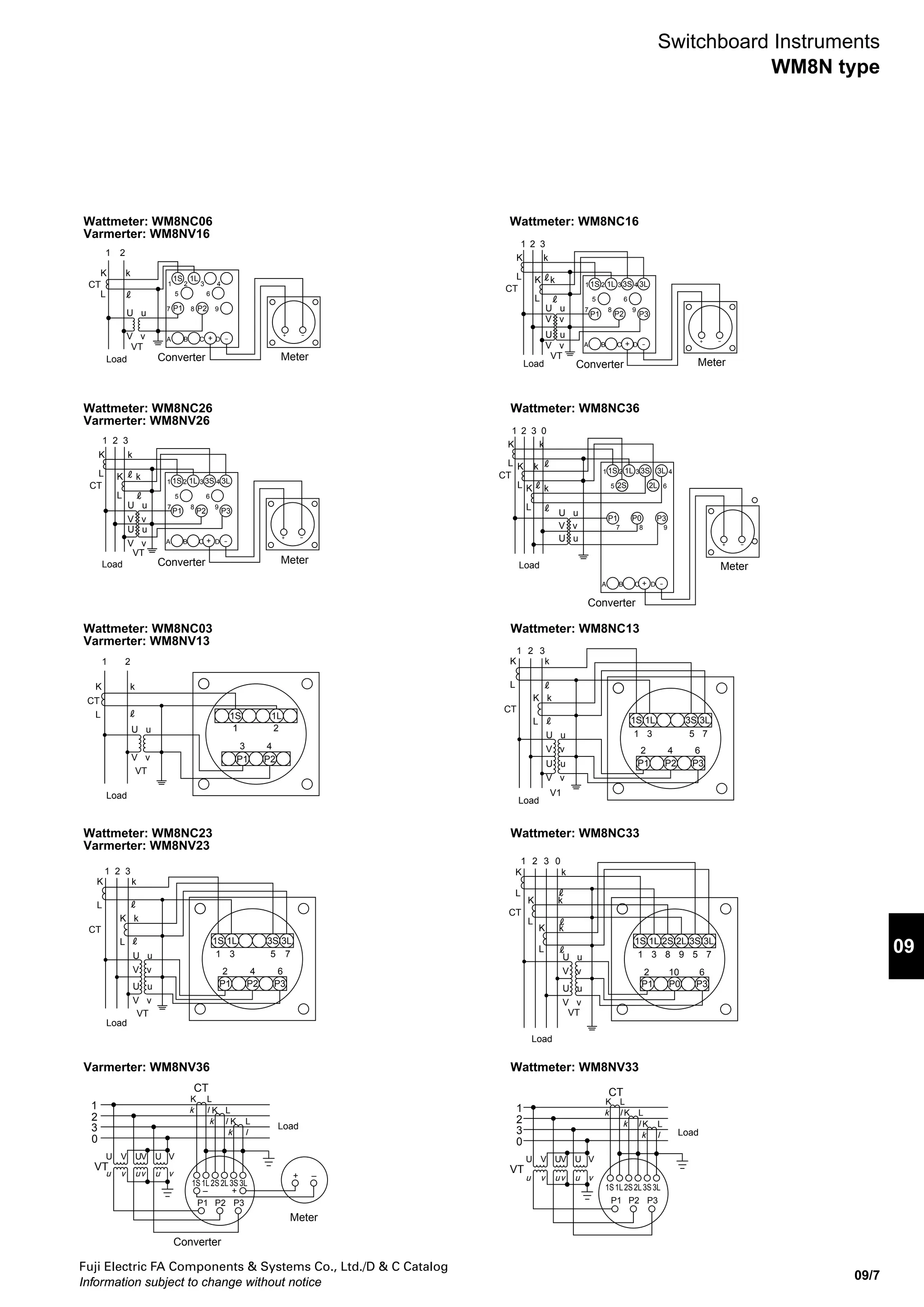
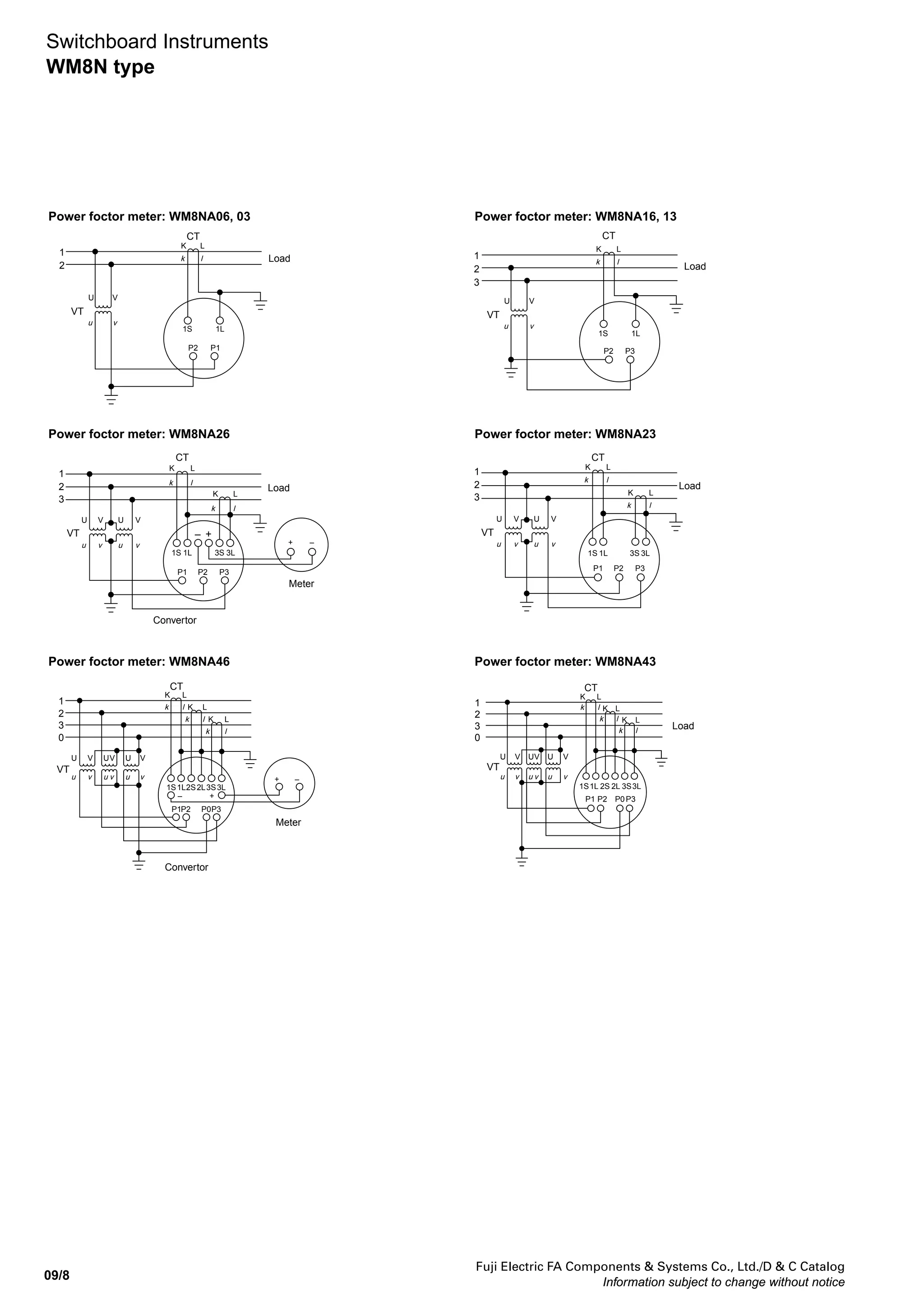
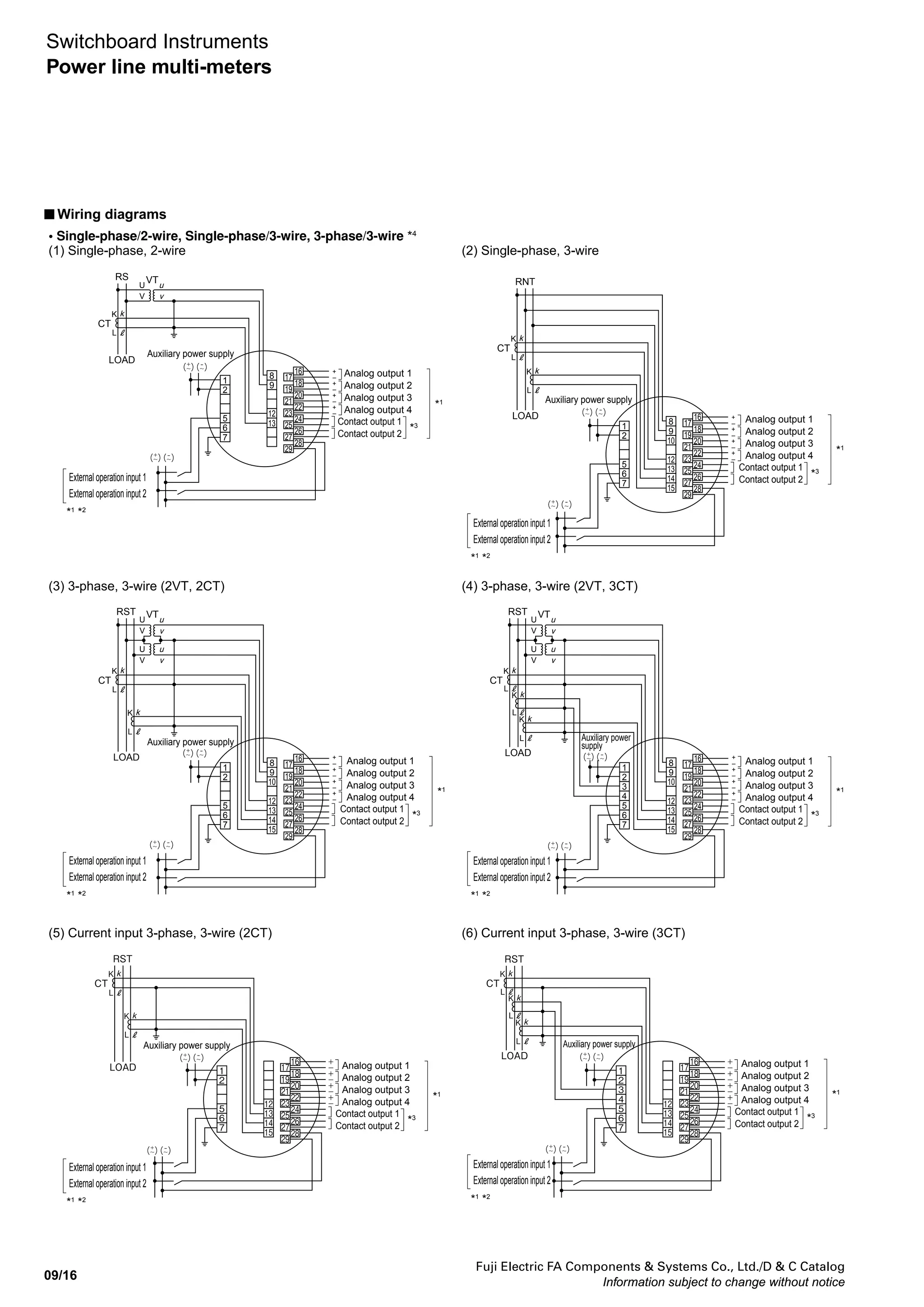
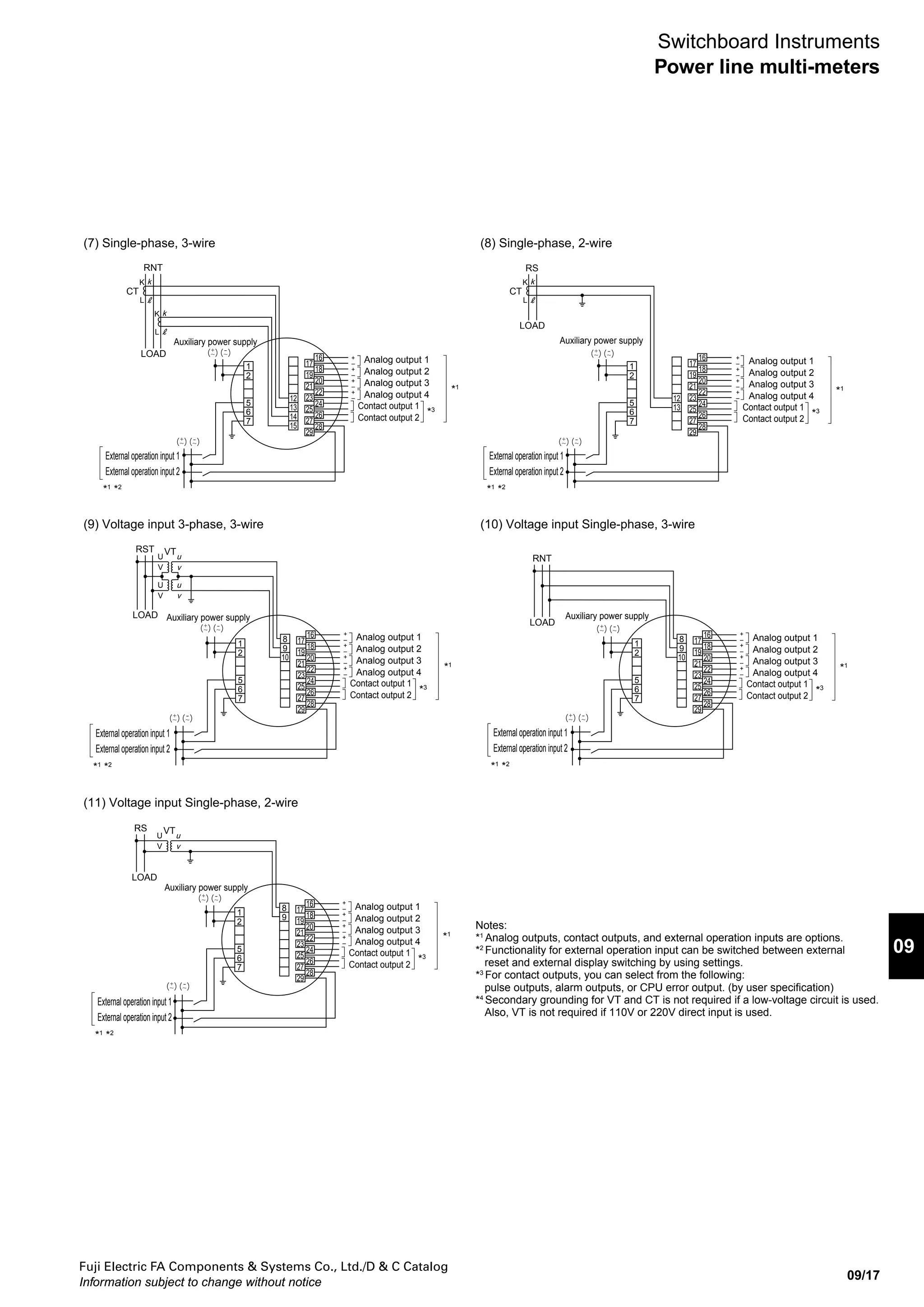
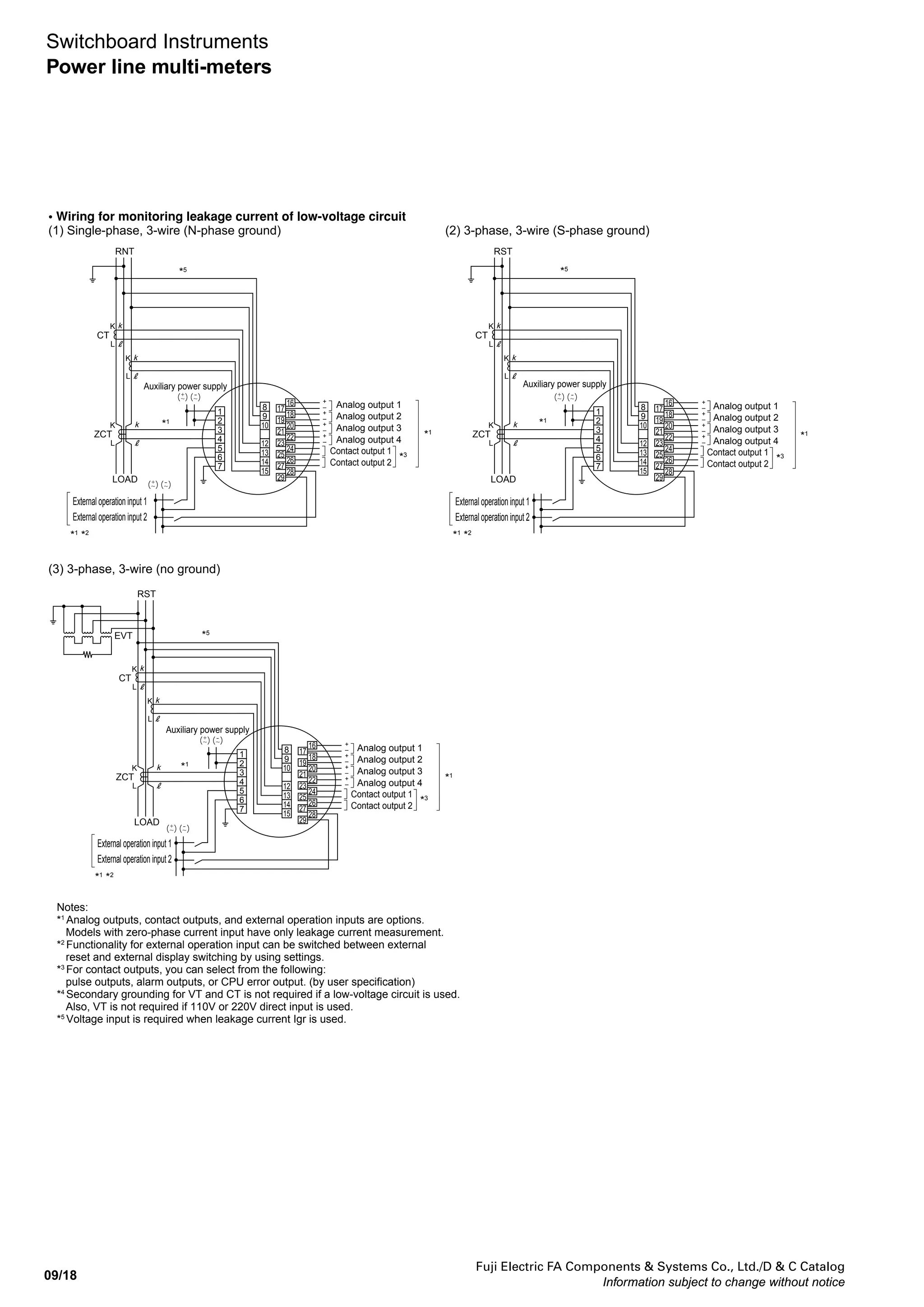
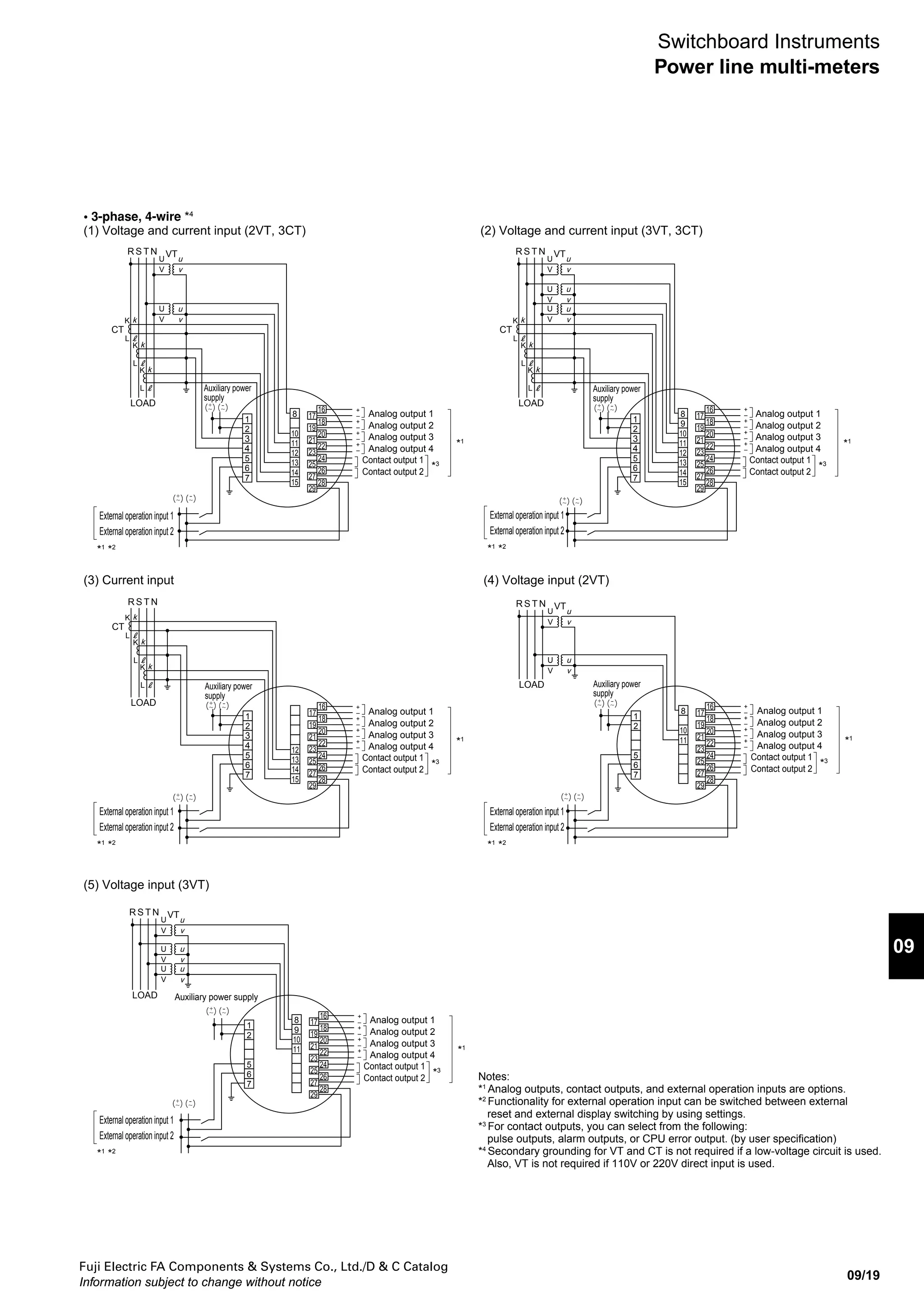
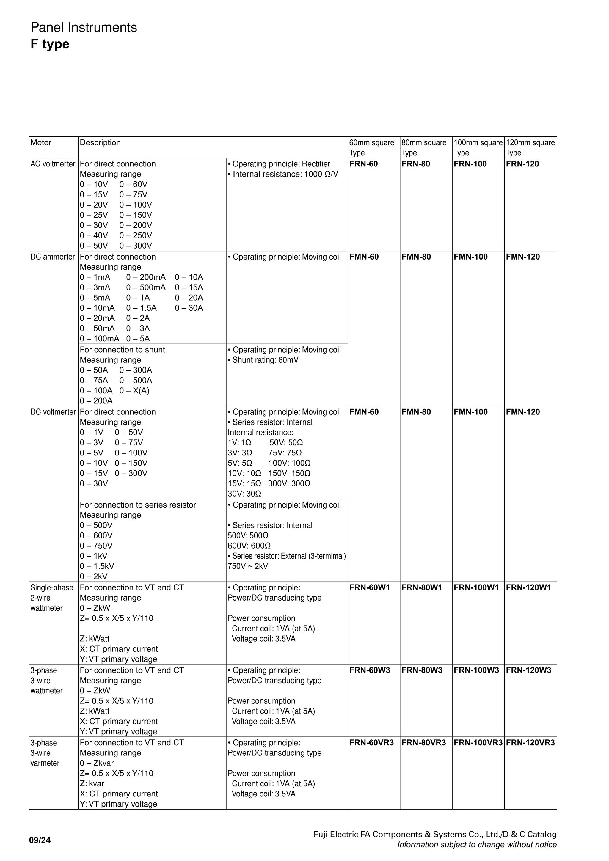
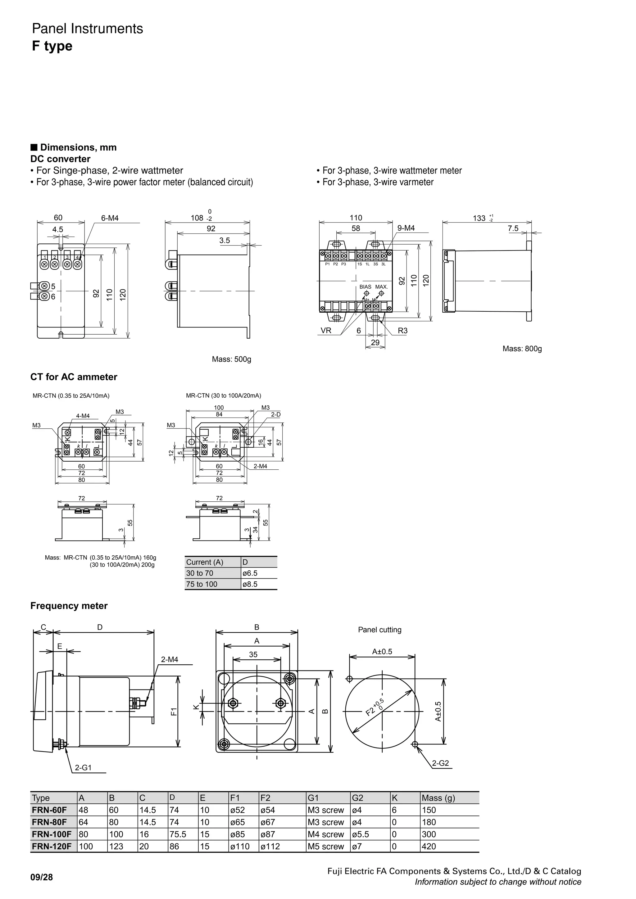
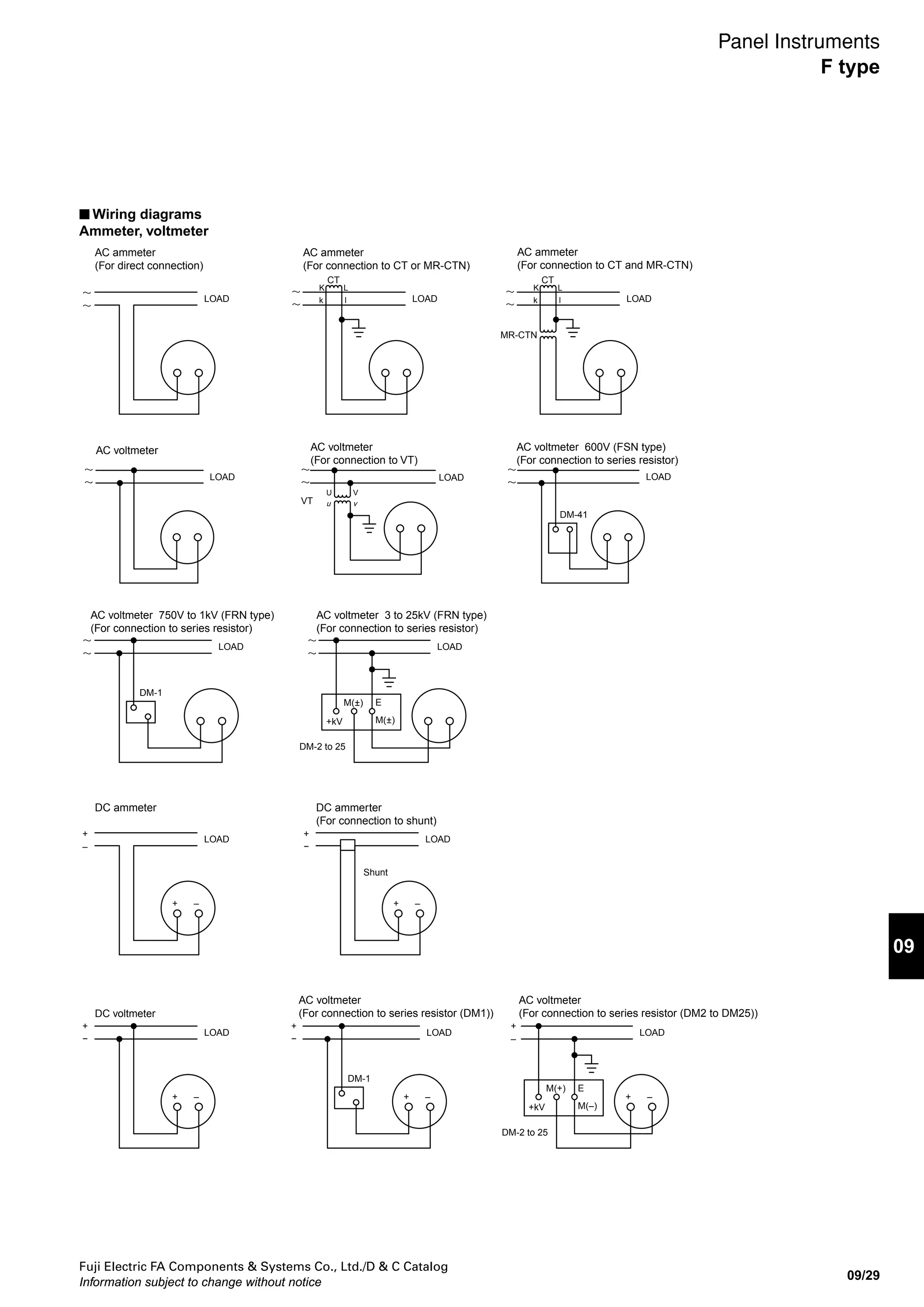
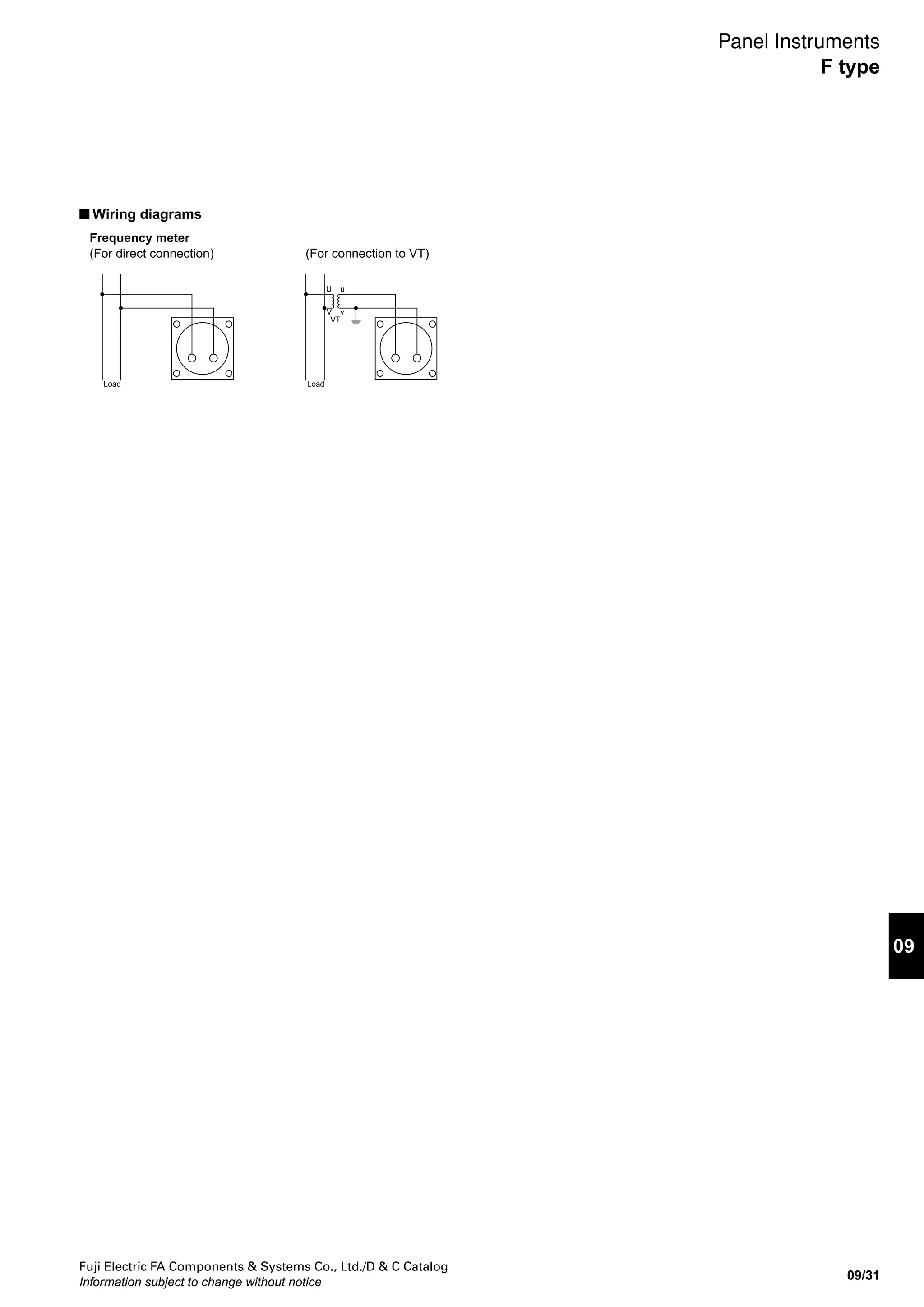
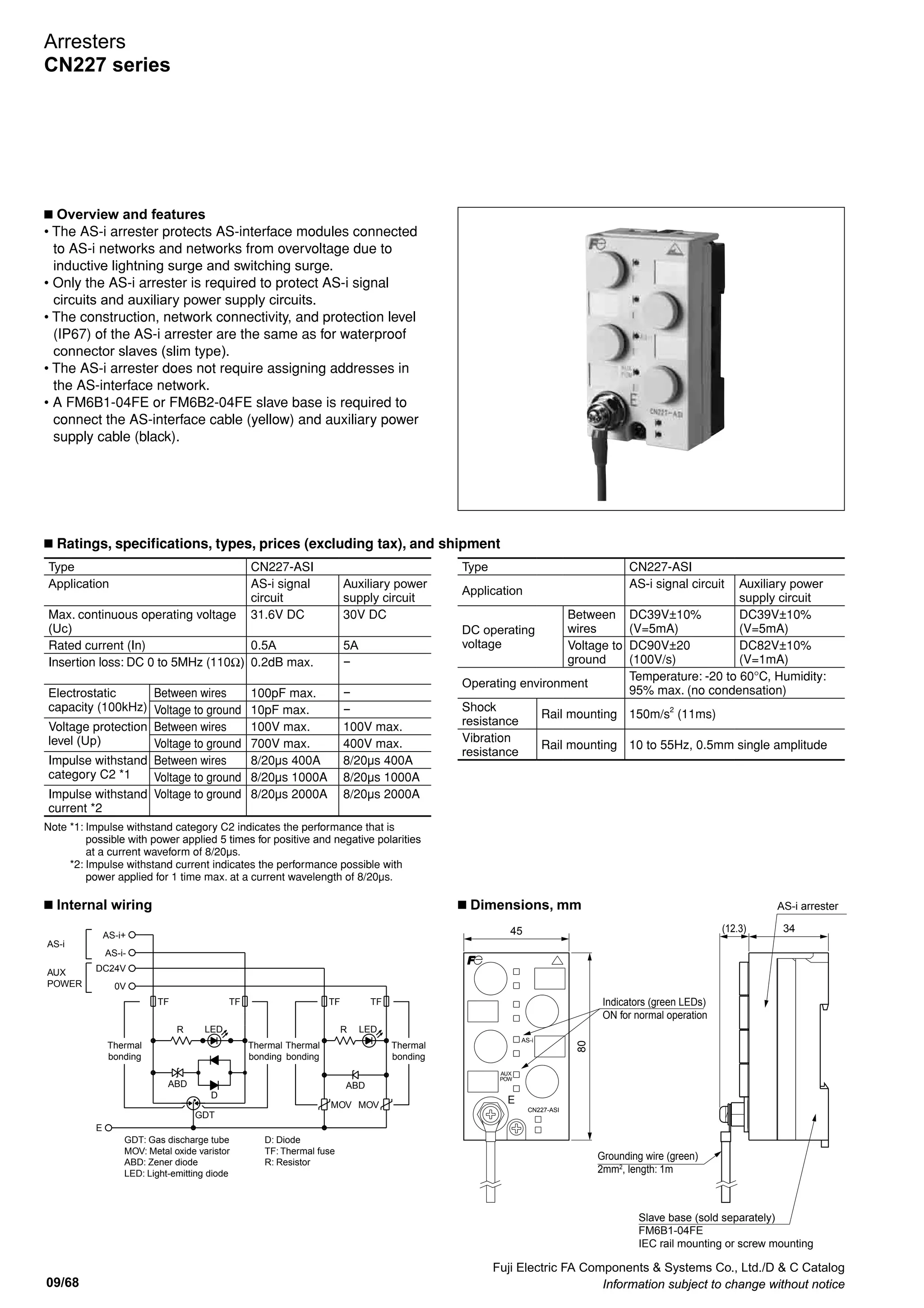
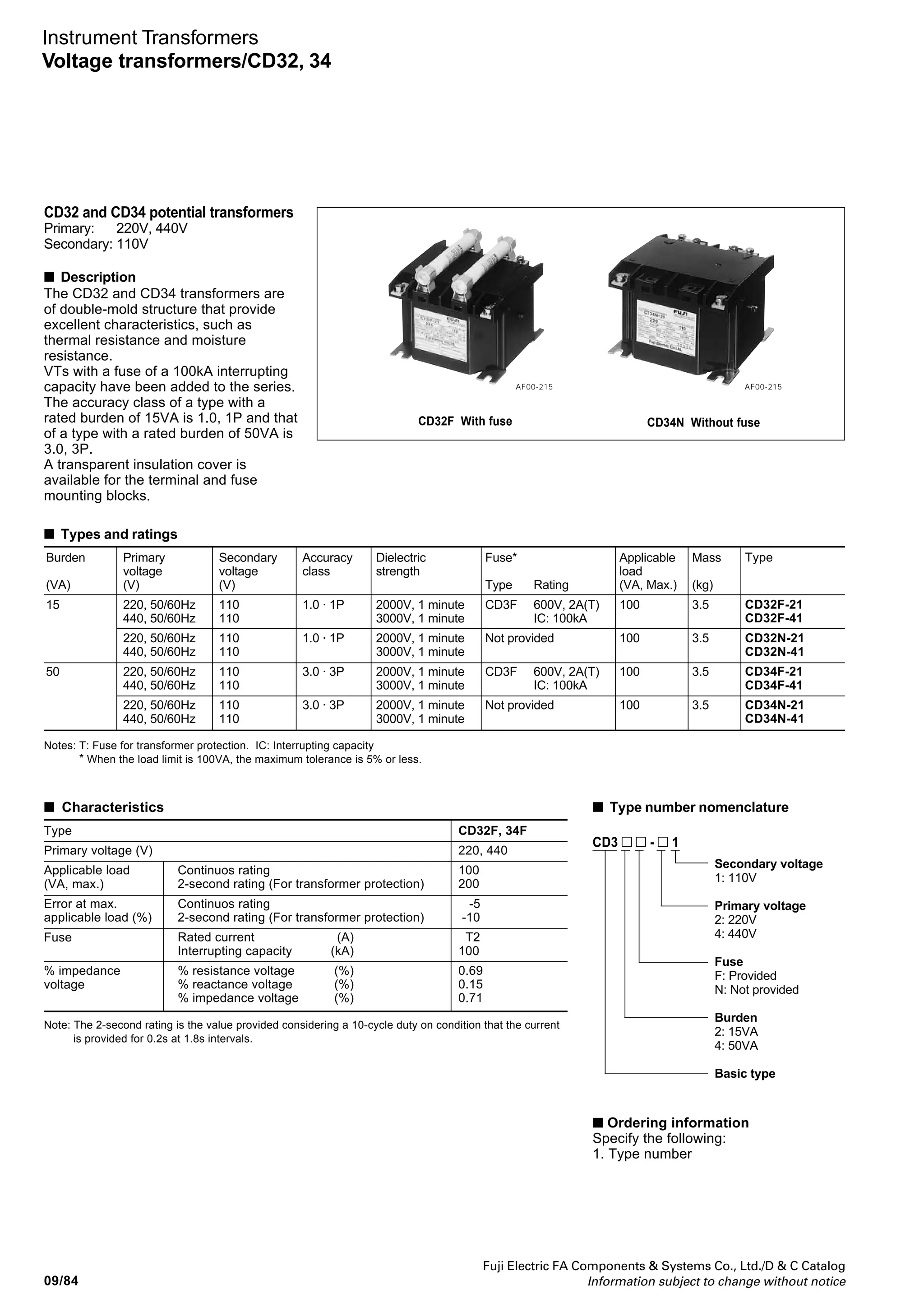
Switchboard Instruments
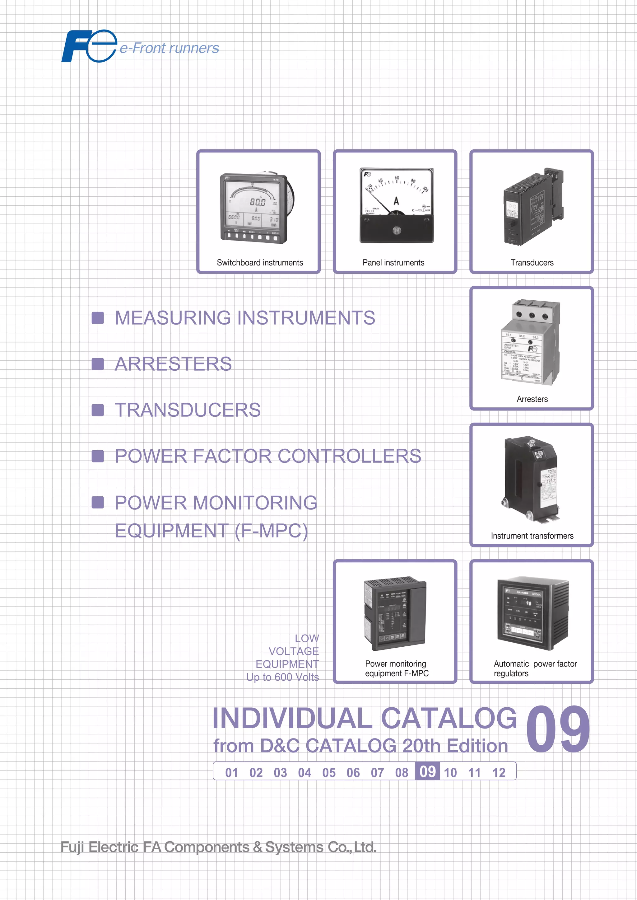
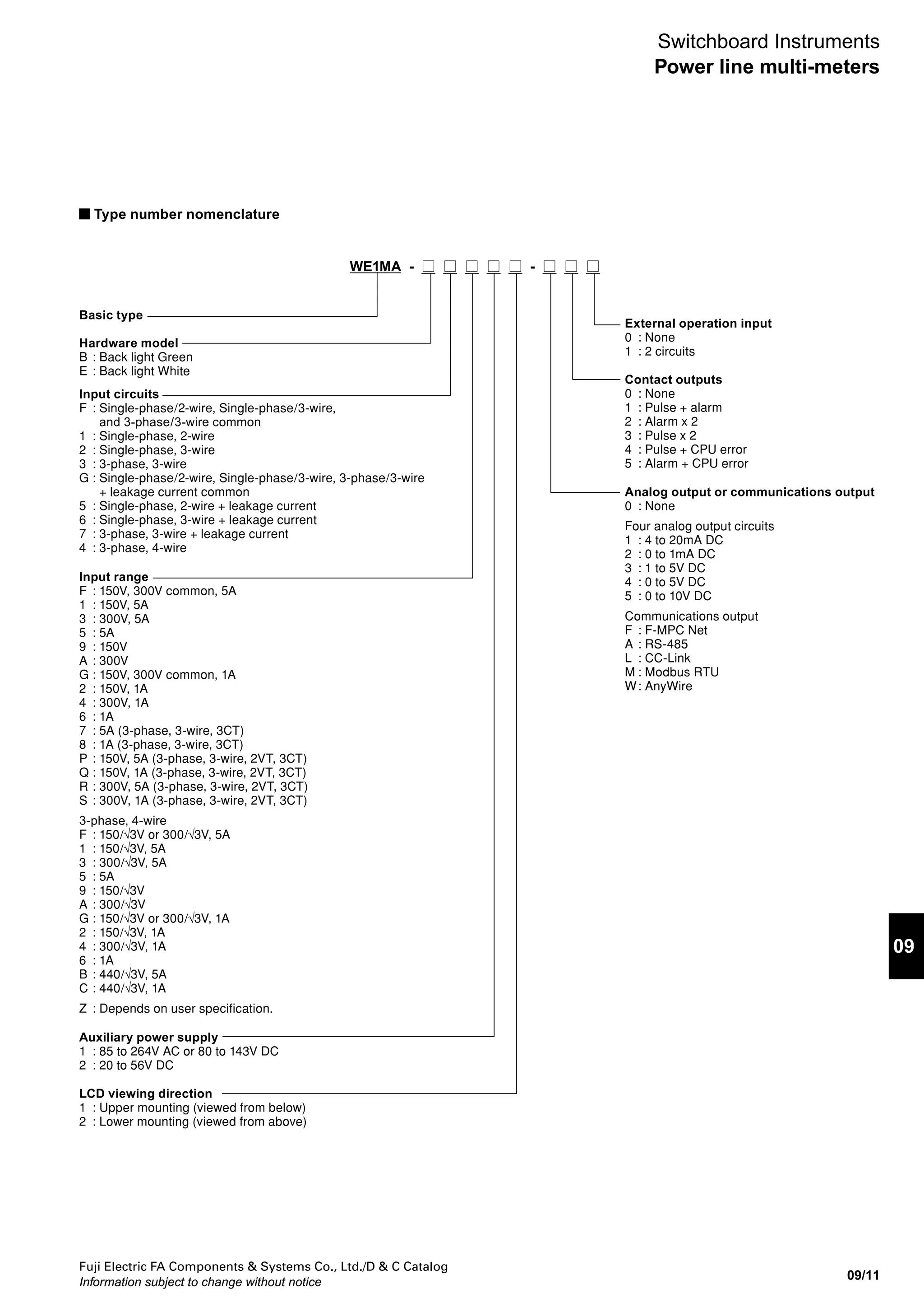
WM8N type
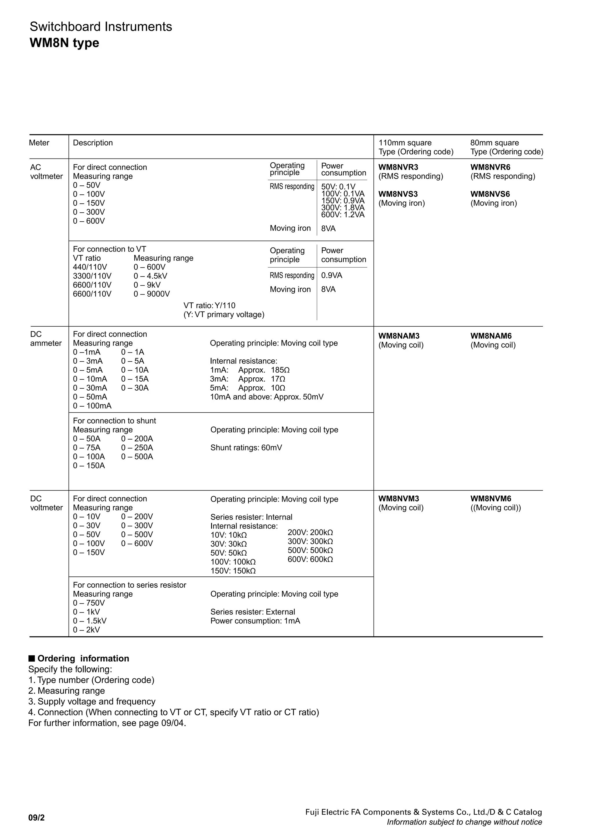
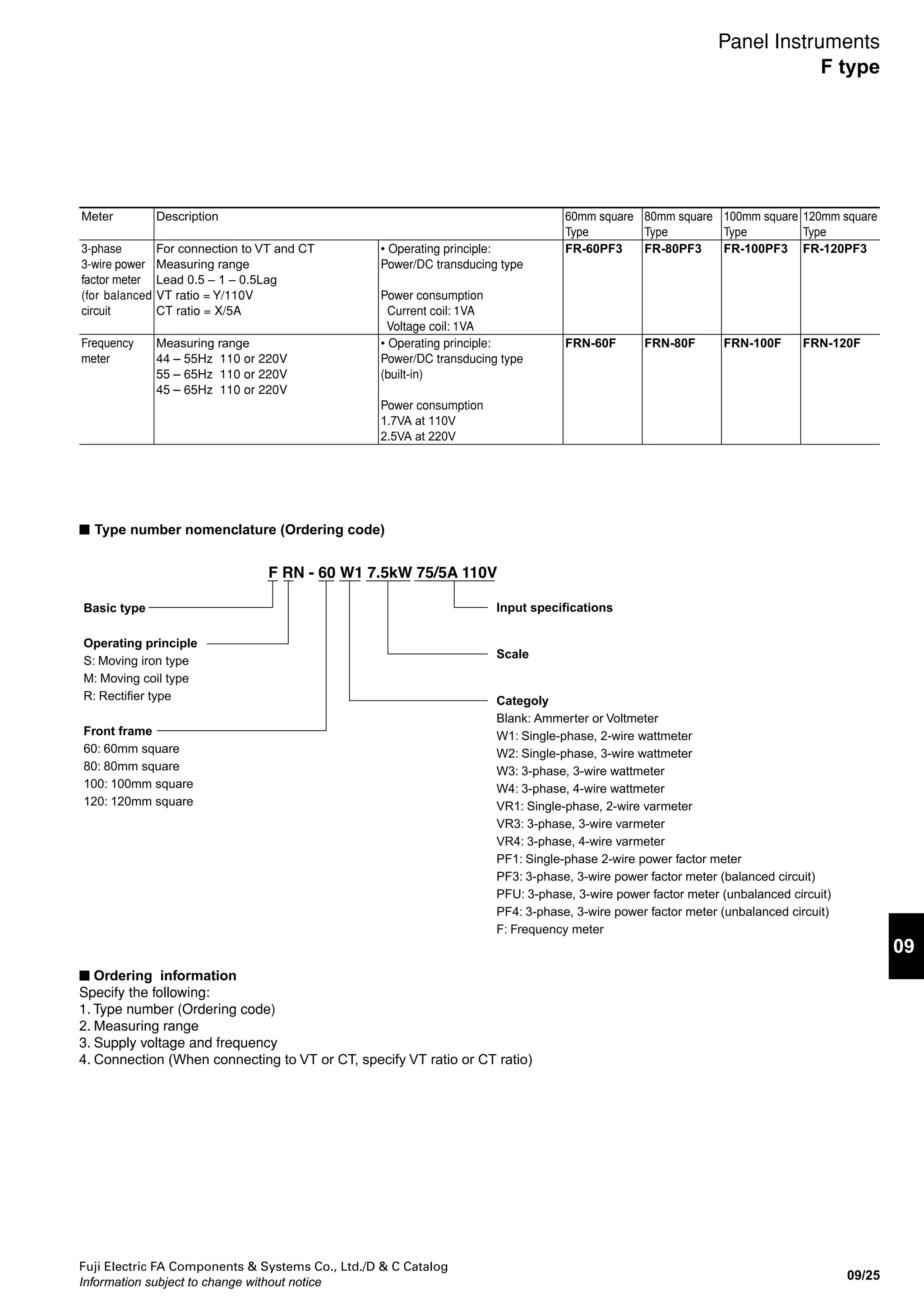
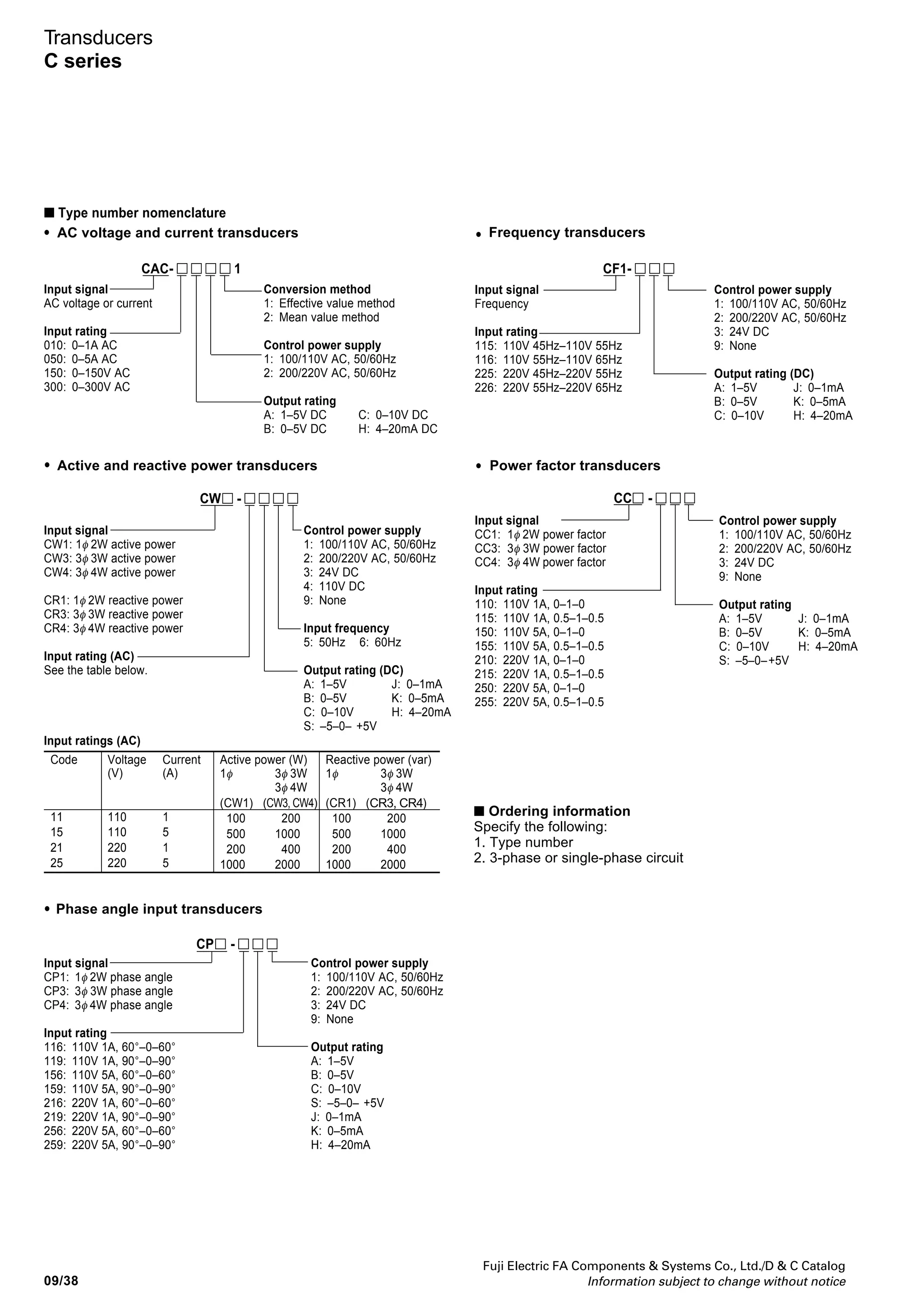
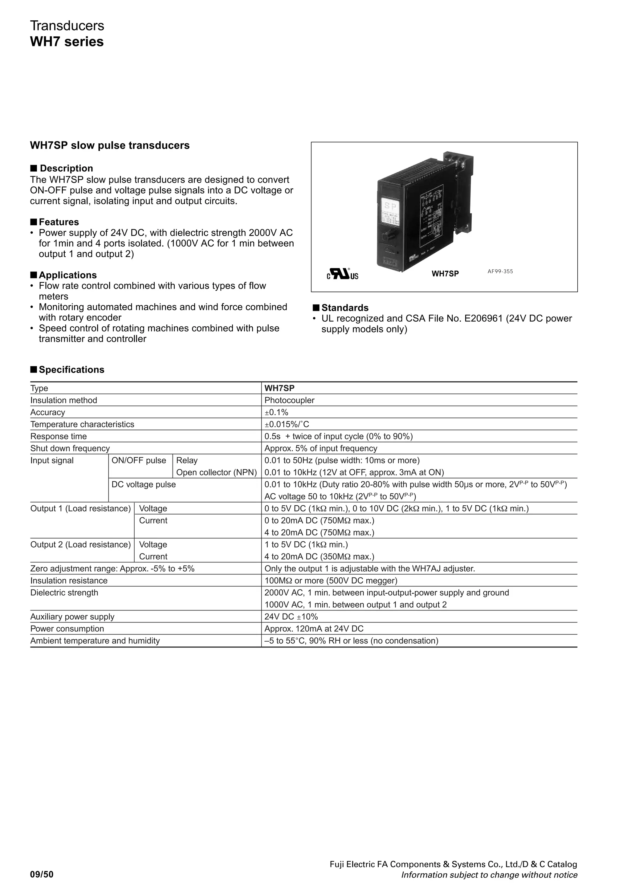
Type number nomenclature
WM8N AR 3 - ALS 5YYY A Y
Basic type
Category
AR : AC ammeter (including reception indicator)
AS : AC ammeter (moving iron type only)
VR : AC voltmeter (including reception indicator)
VS : AC voltmeter (moving iron type only)
AM : DC ammeter (moving coil type only)
VM : DC voltmeter (moving coil type only)
C0 : Single-phase, 2-wire wattmeter
C1 : Single-phase, 3-wire wattmeter
C2 : 3-phase, 3-wire wattmeter
C3 : 3-phase, 4-wire wattmeter
A0 : Single-phase, 2-wire power factor meter
A1 : 3-phase power factor meter for balanced circuit
A2 : 3-phase power factor meter for unbalanced circuit
A4 : 3-phase, 4-wire power factor meter for unbalanced circuit
P1 : Frequency meter
V1 : Single-phase, 2-wire varmeter
V2 : 3-phase, 3-wire varmeter
V3 : 3-phase, 4-wire varmeter
AT : 3-phase, 3-wire current power factor meter
Additional specifications
Y : None (standard specification)
R : Setting pointer equipped (red)
Z : The following additional specifications
(Specify the content.)
[Additional specifications]
Single scale/double printing, double scale/double
printing color line, color band, colored characters,
meter installation orientation processing for transit
through tropical areas
Scale unit
1 : %
2 : m
3 : mm
4 : m3
/h
5 : Nm3
/h
6 : ppm
7 : rpm
8 : o
C
9 : l/h
A : A
B : µA
C : cos
D : mA
E : kA
F : m3
/s
G : min-1
H : Hz
J : Mvar
K : kvar
L : var
M : MPa
N : kPa
P : Pa
Q : pH
R : t/h
S : MW
T : kV
U : mV
V : V
W : mg/l
X : kW
Y : x kV
Z : Not given above.
(Be sure to specify.)
Scale numbers
:
Specify the scale numbers with four digits. Enter
the specification from the left, and enter "Y" for any
remaining digits.Enter "R" for a decimal point. If the
scale unit is factored, specify the following at the
end: S for x1000, H for x100, or T for x10.
Example 1 : 500V Specify “500Y”.
Example 2 : 5V Specify “5YYY”.
Example 3 : 5.5V Specify “5R5Y”.
Example 4 : 5kV Specify “5YYY”.
Example 5 : 5000V Specify “5000”.
Example 6 : 1000ppm Specify “1000”.
Example 7 : 1 x 1000ppm Specify “1YYS”.
Example 8 : 4.7 x 100ppm Specify “4R7H”.
Example 9 : 4.7 x 10ppm Specify “4R7T”.
Example 10 : ± scale Specify “ZZZZ” and specify
the scale.For an extended scale,
specify the effective scale range
(standard scale portion).
Example 11 : 10/5A times 3 extension Specify “10YY”.
CS05 : Power factor meter 0.5 - 1 - 0.5
CST0 : Current power factor meter 0 - 1 - 0 - 1 - 0
HZYY : Frequency meter
01ML *3
: 0 - 1 - 0 (power factor linear scale)
01MN *3
: 0 - 1 - 0 (phase angle linear scale)
05ML *3
: 0.5 - 1 - 0.5 (power factor linear scale)
05MN *3
: 0.5 - 1 - 0.5 (phase angle linear scale)
ZZZZ : Specifications not given above.
(Be sure to specify the scale.)
*3
Power factor display for DC ammeter and voltmeter
(reception indicator).
*1
If a CT or VT is used, be sure to specify the CT
ratio or VT ratio.(If a power factor meter is used,
the CT ratio or VT ratio does not have to be
specified.) Also, if a power factor meter for an
unbalanced circuit is used, be sure to specify the
rated frequency.
*2
Table of rated voltages
: Can be produced, : Cannot be produced.
Category Voltage
between
wires:
100V
110 to 220V
105 to 210V
100 to 200V
Voltage
between
wires:
220V
Single-phase, 2-wire wattmeter/
power factor meter
Single-phase, 3-wire wattmeter
3-phase, 3-wire wattmeter
3-phase, 4-wire wattmeter
3-phase power factor meter for
balanced circuit
3-phase power factor meter for
unbalanced circuit
3-phase, 4-wire power factor meter
Single-phase, 2-wire varmeter
3-phase, 3-wire varmeter
3-phase, 4-wire varmeter
Rated Input
AC ammeter (AC) *1
For direct connection
Standard ALA : 0 to 1A
ALJ : 0 to 3A
ALS : 0 to 5A
AMT : 0 to 10A
AND : 0 to 15A
ANG : 0 to 20A
ANL : 0 to 30A
2 times A2Z : Order production
3 times A32 : 0 to 1A times 3
A34 : 0 to 3A times 3
A35 : 0 to 5A times 3
A36 : 0 to 10A times 3
A37 : 0 to 15A times 3
A38 : 0 to 20A times 3
A39 : 0 to 30A times 3
(moving iron type only)
5 times A52 : 0 to 1A times 5
A55 : 0 to 5A times 5
For CT connection
Standard A41 : A/1A
A42 : A/5A
2 times A43 : A/1A times 2
A44 : A/5A times 2
3 times A45 : A/1A times 3
A46 : A/5A times 3
5 times A47 : A/1A times 5
A48 : A/5A times 5
Special ZZZ : 0 to 100mA min. to 0 to 30A max.
(Be sure to specify the input value.)
AC voltmeter (AC) *1
For direct connection
VNT : 0 to 50V
VPK : 0 to 100V
VPZ : 0 to 150V
VRX : 0 to 300V
VSJ : 0 to 600V
For VT connection
V12 : 0 to 150V
V13 : 0 to 150/√3V
Special
ZZZ : 0 to 50V min. to 0 to 600V max.
(Be sure to specify the input value.)
Frequency meter
Standard H10 : 110V 45 to 55Hz
H11 : 110V 55 to 65Hz
H12 : 110V 45 to 65Hz
H20 : 220V 45 to 55Hz
H21 : 220V 55 to 65Hz
H22 : 220V 45 to 65Hz
Special ZZZ : Specifications not given above.
(Be sure to specify the input value.)
Wattmeter, varmeter, and power factor meter *1
*2*4
Standard D13 : 110V/1A
D14 : 110V/5A
D15 : 220V/1A
D16 : 220V/5A
D20 : 110 to 220V/5A
Special ZZZ : Specifications not given above.
(Be sure to specify the input value.)
DC ammeter (DC)
Standard AFA : 0 to 1mA
AFN : 0 to 3mA
AFX : 0 to 5mA
AGZ : 0 to 10mA
AHM : 0 to 30mA
AHY : 0 to 50mA
AJR : 0 to 100mA
AKG : 0 to 300mA
AKM : 0 to 500mA
ALA : 0 to 1A
ALC : 0 to 1.5A
ALE : 0 to 2A
ALJ : 0 to 3A
ALS : 0 to 5A
AMT : 0 to 10A
AND : 0 to 15A
ANG : 0 to 20A
ANL : 0 to 30A
A04 : 0 to 60mV (for shunt)
A05 : 0 to 100mV (for shunt)
AHE : 4 to 20mA
AHH : 4 to 25.3mA
DEM : ±500µA
D04 : ±60mV (for shunt)
D08 : 0 to 100mV (for shunt, with VR)
Special
ZZZ : Be sure to specify an input value
in the range of 0 to 300µA min.
to 0 to 1A max.
DC voltmeter (DC)
Standard VLA : 0 to 1V
VLJ : 0 to 3V
VLS : 0 to 5V
VMT : 0 to 10V
VNL : 0 to 30V
VNT : 0 to 50V
VPB : 0 to 75V
VPK : 0 to 100V
VPZ : 0 to 150V
VRL : 0 to 200V
VRX : 0 to 300V
VSF : 0 to 500V
VSJ : 0 to 600V
VLR : 1 to 5V
V01 : For connection to external series resistor
Special
ZZZ : 0 to 50mV min. to 0 to 600V max.
(Be sure to specify the input value.)
*4
The rated voltage for the 3-phase, 4-wire type is
the voltage between wires.
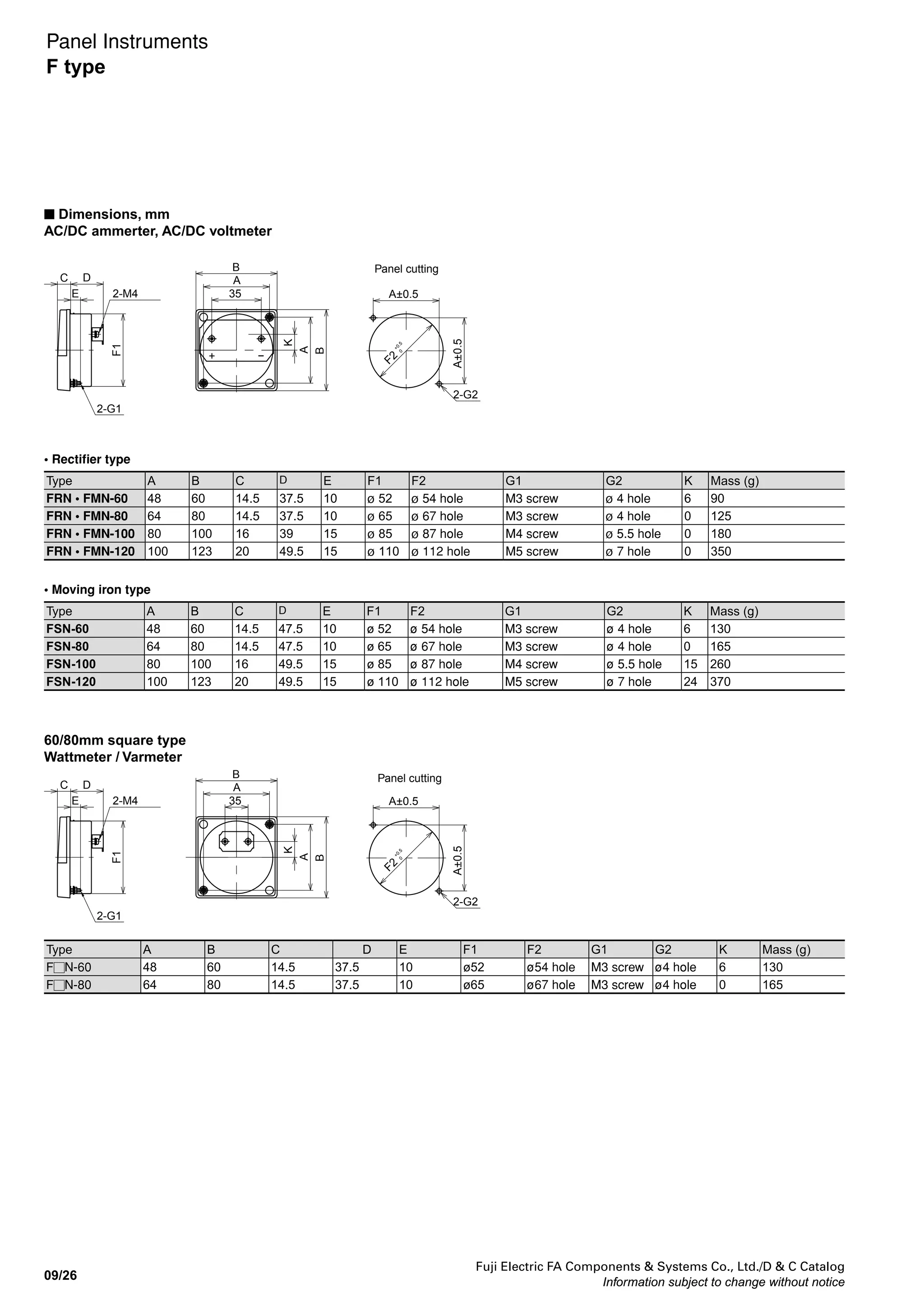
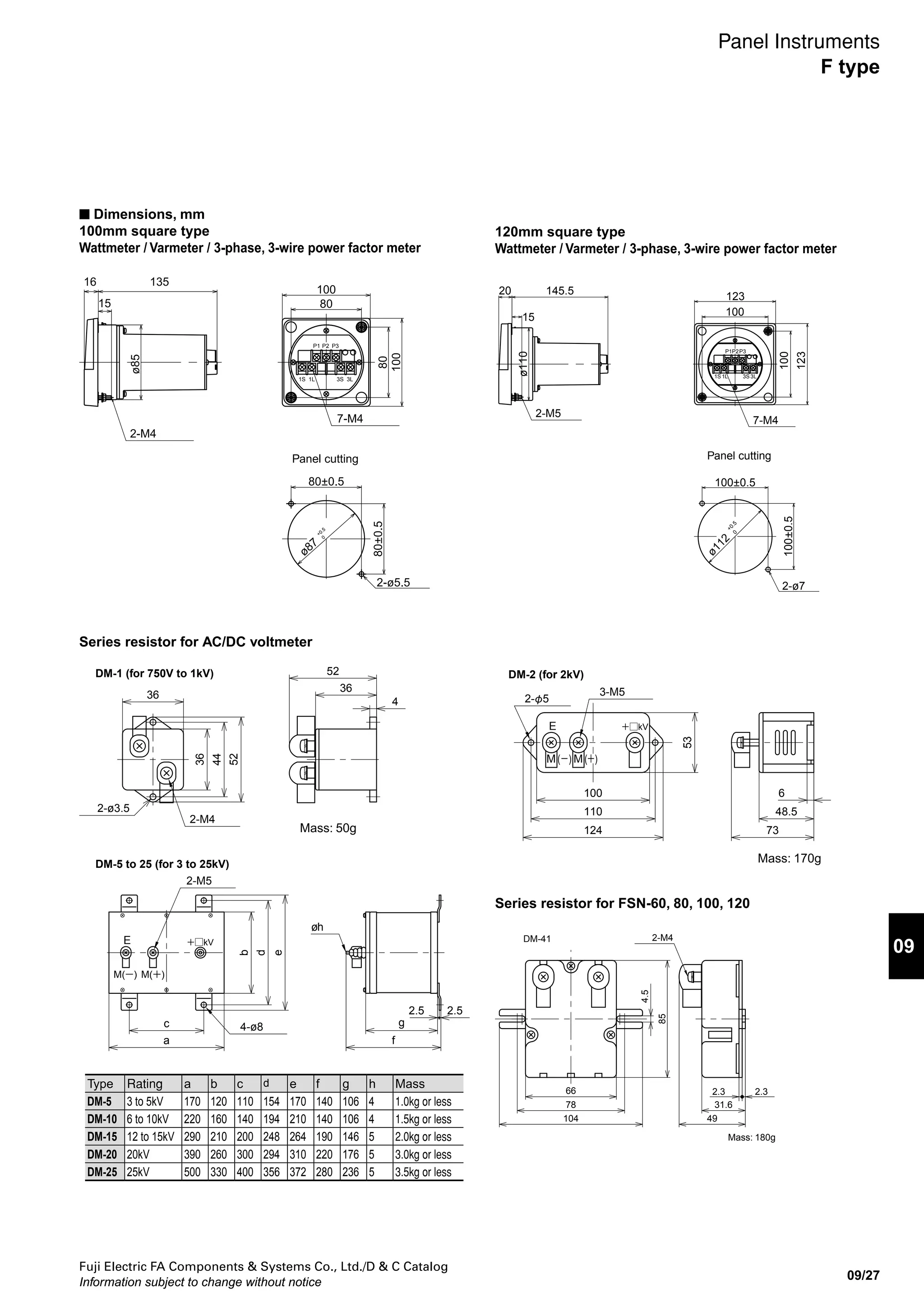
Dimensions
3 : 110 x 110mm
6 : 80 x 80mm](https://image.slidesharecdn.com/dec2009-measuringinstuments-141201203626-conversion-gate01/75/09-Measuring-Instuments-Fuji-Electric-8-2048.jpg)


![Fuji Electric FA Components Systems Co., Ltd./D C Catalog
Information subject to change without notice 09/51
09
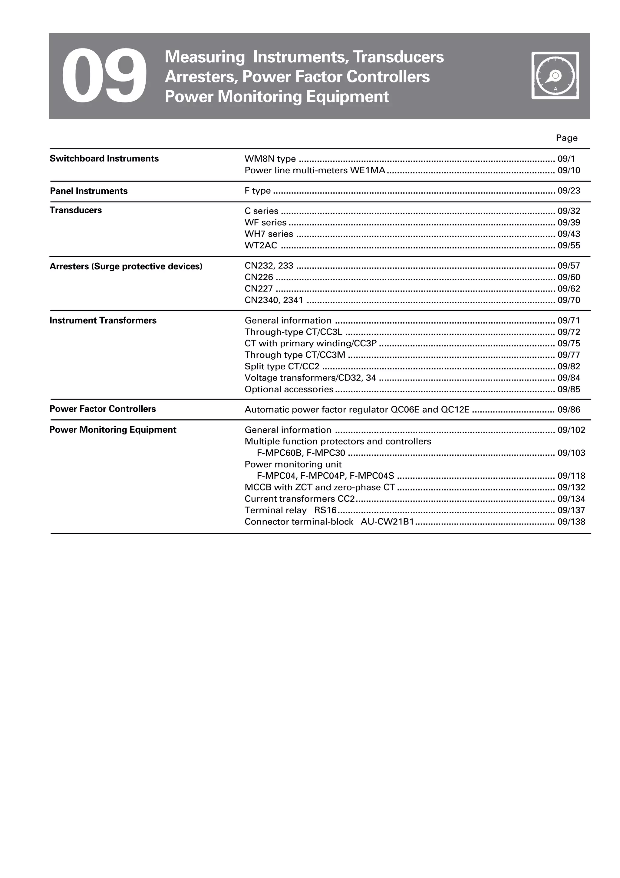
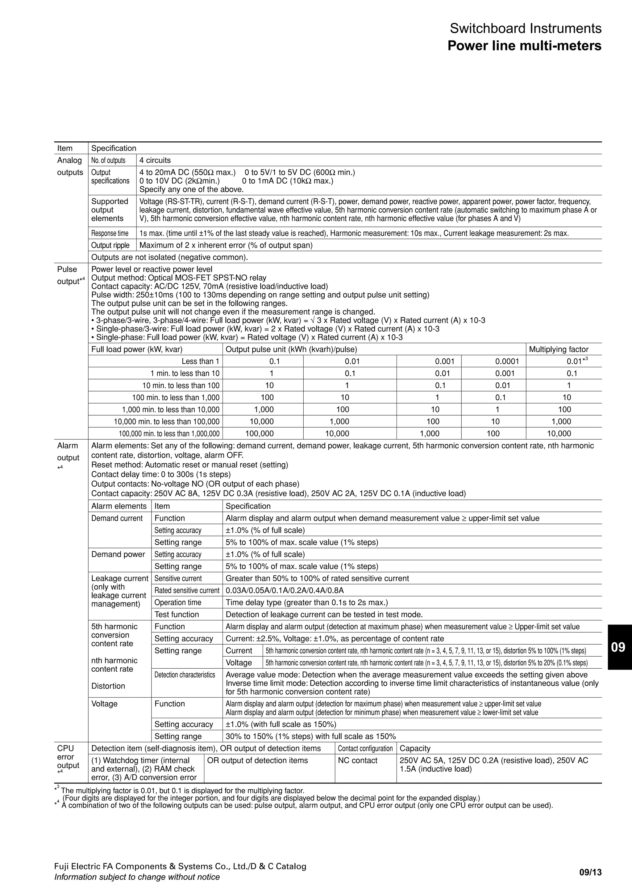
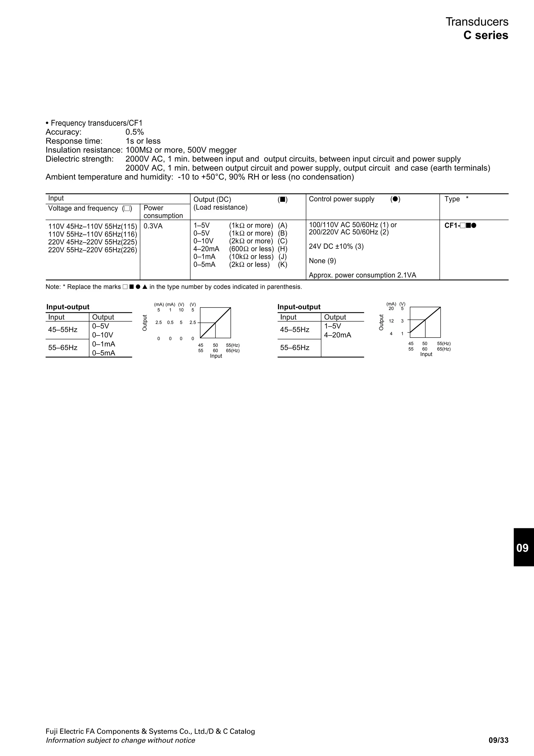
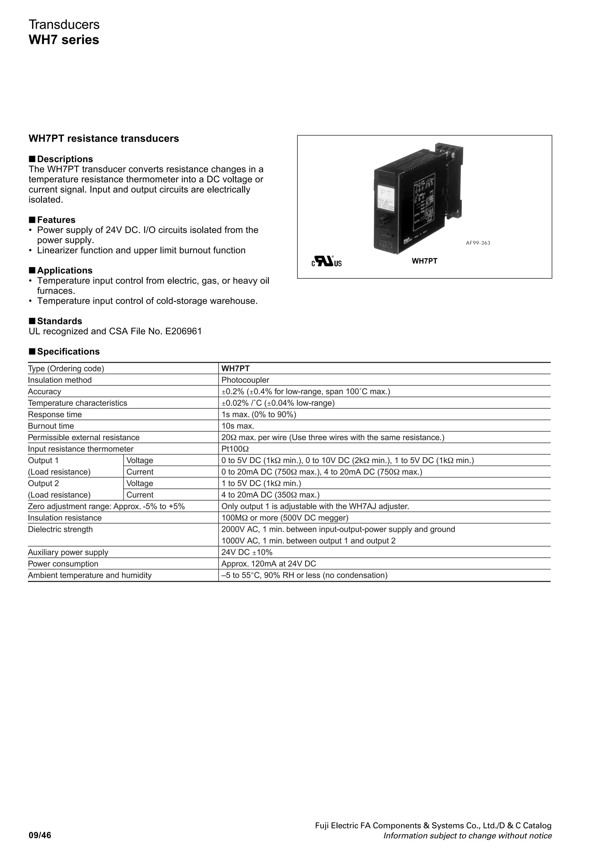
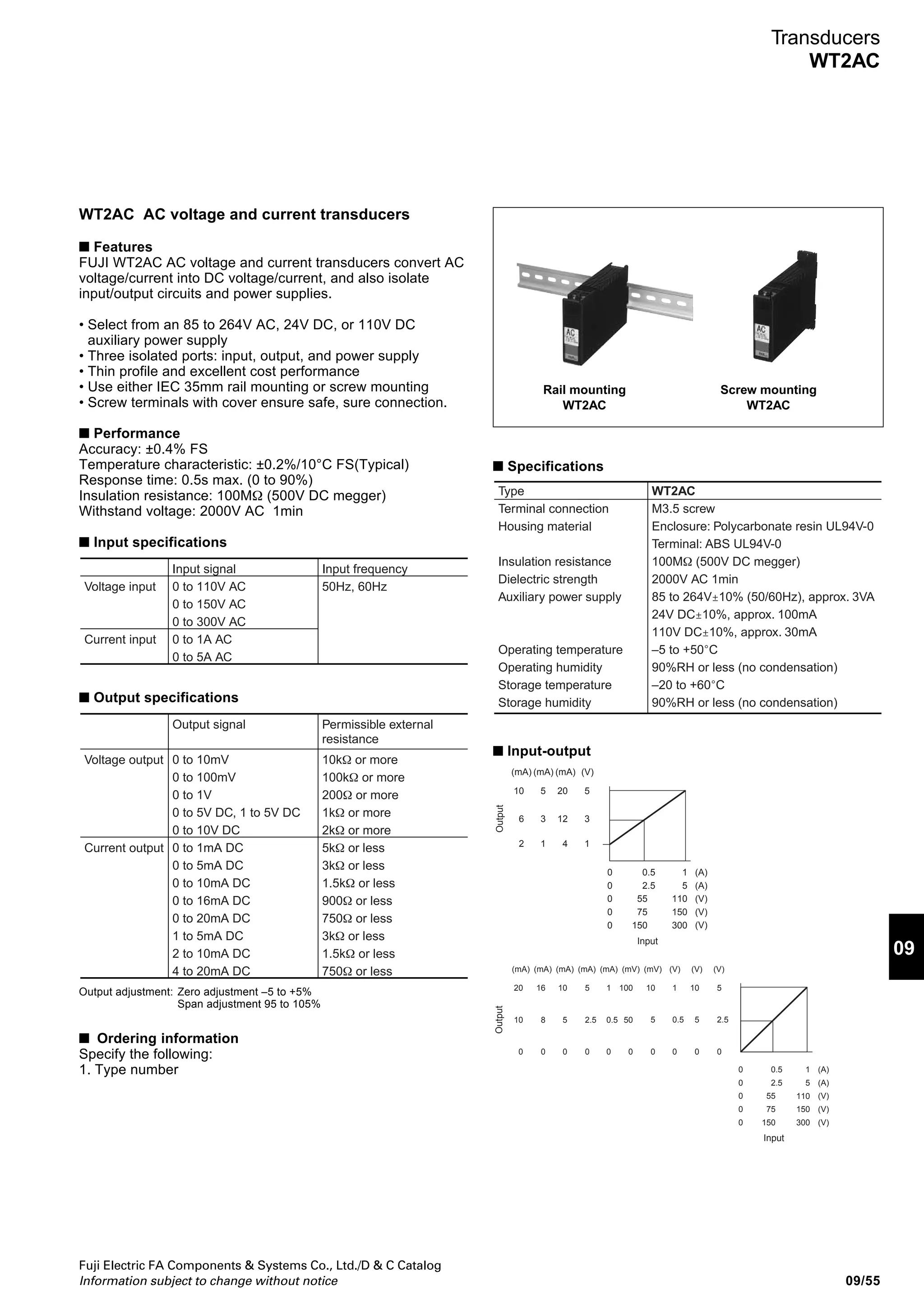
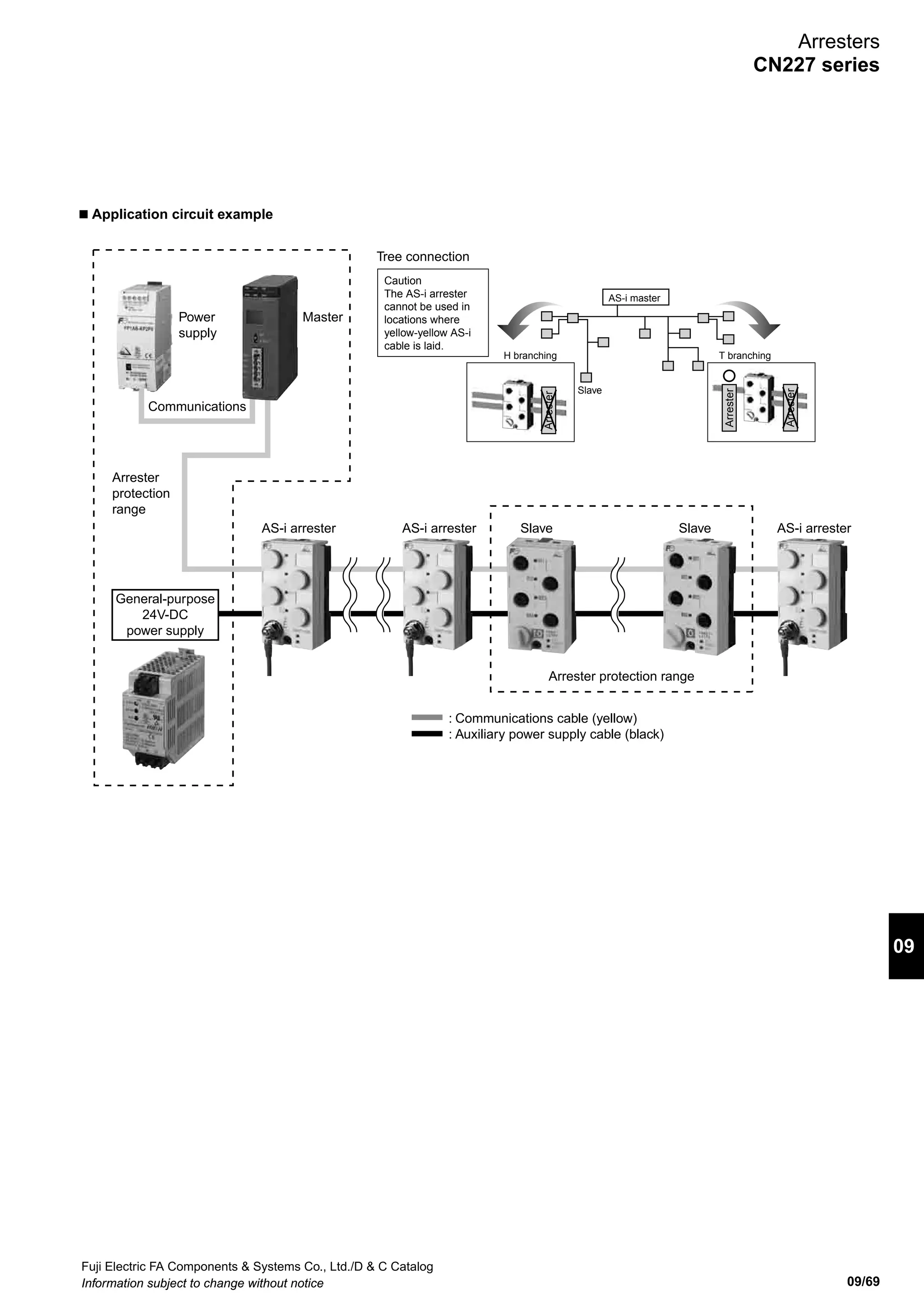
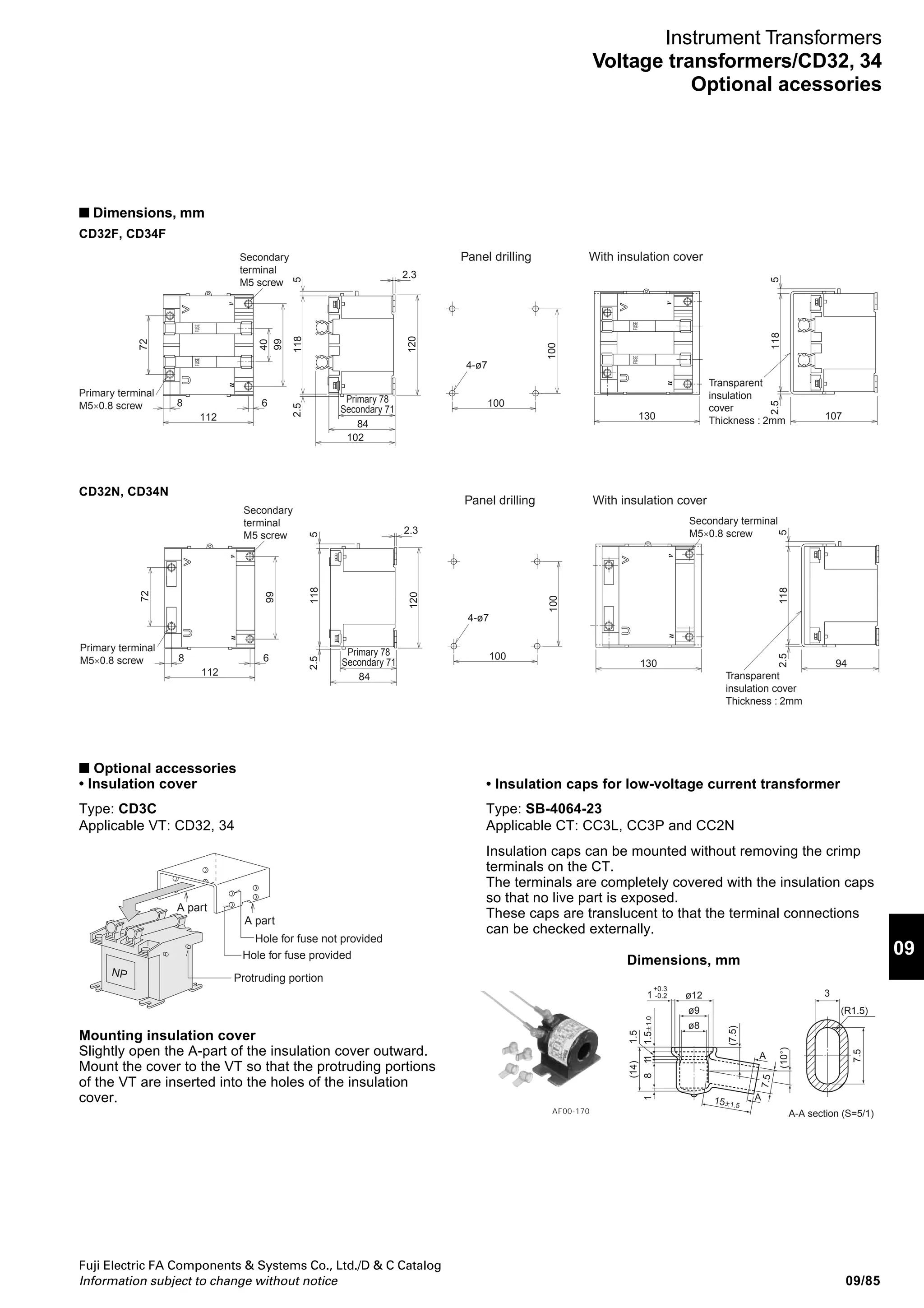
Transducers
WH7 series
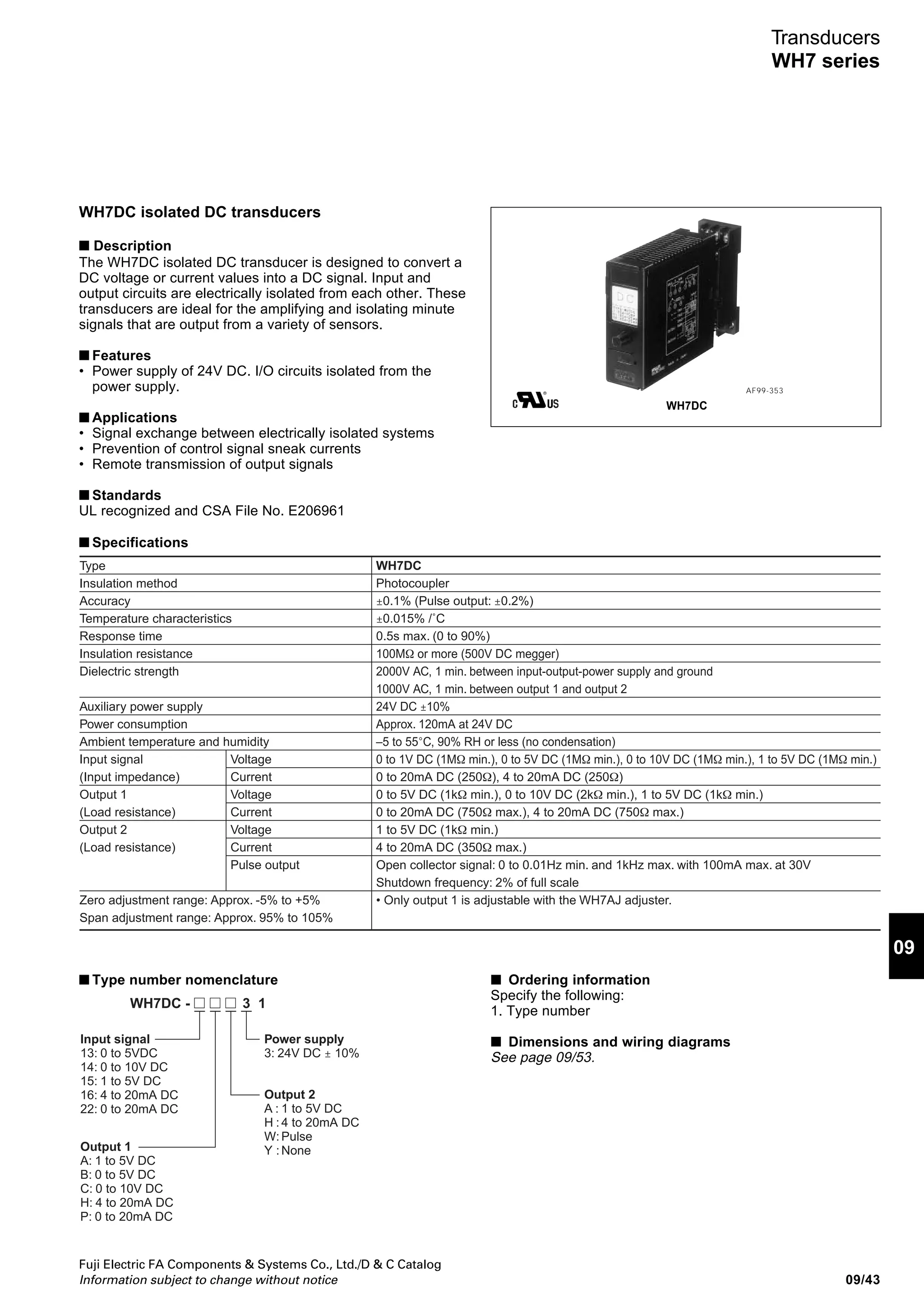
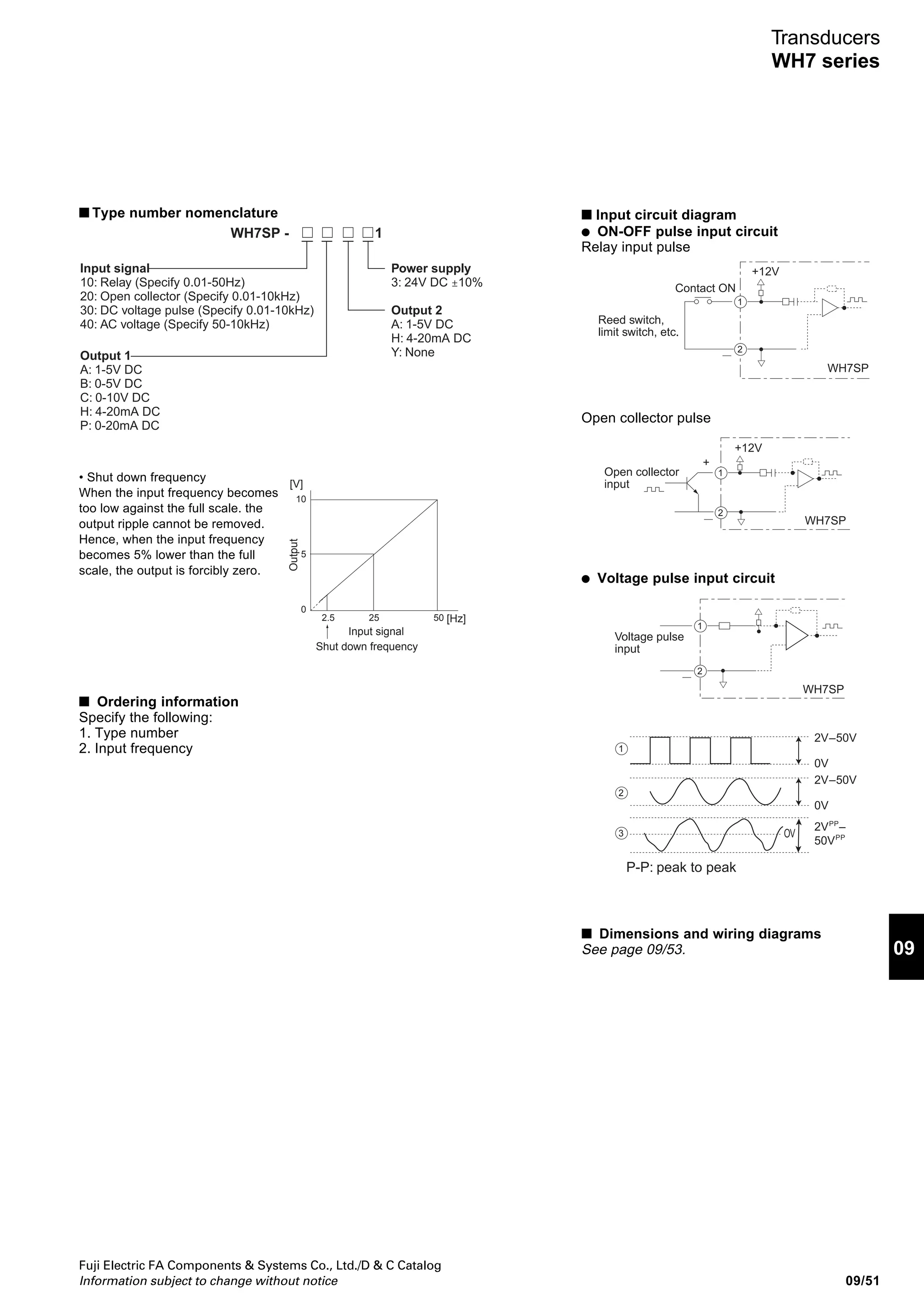
■ Type number nomenclature
• Shut down frequency
When the input frequency becomes
too low against the full scale. the
output ripple cannot be removed.
Hence, when the input frequency
becomes 5% lower than the full
scale, the output is forcibly zero.
10
5
0
2.5 25 50
[V]
[Hz]
Output
Input signal
Shut down frequency
Power supply
3: 24V DC ±10%
Output 2
A: 1-5V DC
H: 4-20mA DC
Y: None
Input signal
10: Relay (Specify 0.01-50Hz)
20: Open collector (Specify 0.01-10kHz)
30: DC voltage pulse (Specify 0.01-10kHz)
40: AC voltage (Specify 50-10kHz)
Output 1
A: 1-5V DC
B: 0-5V DC
C: 0-10V DC
H: 4-20mA DC
P: 0-20mA DC
WH7SP - 1
■ Ordering information
Specify the following:
1. Type number
2. Input frequency
■ Input circuit diagram
● ON-OFF pulse input circuit
Relay input pulse
Open collector pulse
● Voltage pulse input circuit
■ Dimensions and wiring diagrams
See page 09/53.
1
2
+12V
Contact ON
Reed switch,
limit switch, etc.
WH7SP
Open collector
input
+
+12V
1
2
WH7SP
1
1
2
3
2
Voltage pulse
input
P-P: peak to peak
WH7SP
2VPP
–
50VPP
2V–50V
0V
2V–50V
0V
OV](https://image.slidesharecdn.com/dec2009-measuringinstuments-141201203626-conversion-gate01/75/09-Measuring-Instuments-Fuji-Electric-55-2048.jpg)

![Fuji Electric FA Components Systems Co., Ltd./D C Catalog
Information subject to change without notice09/88
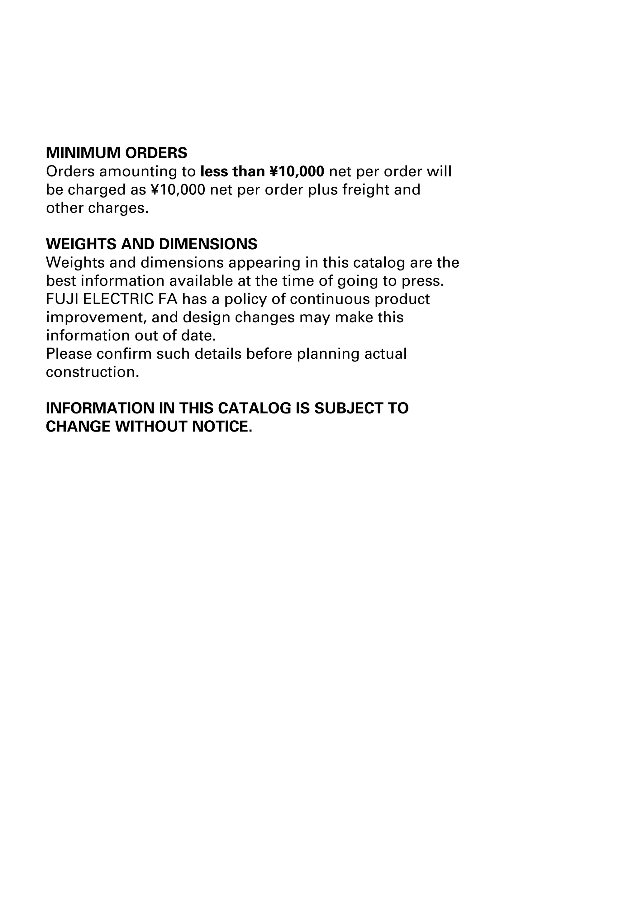
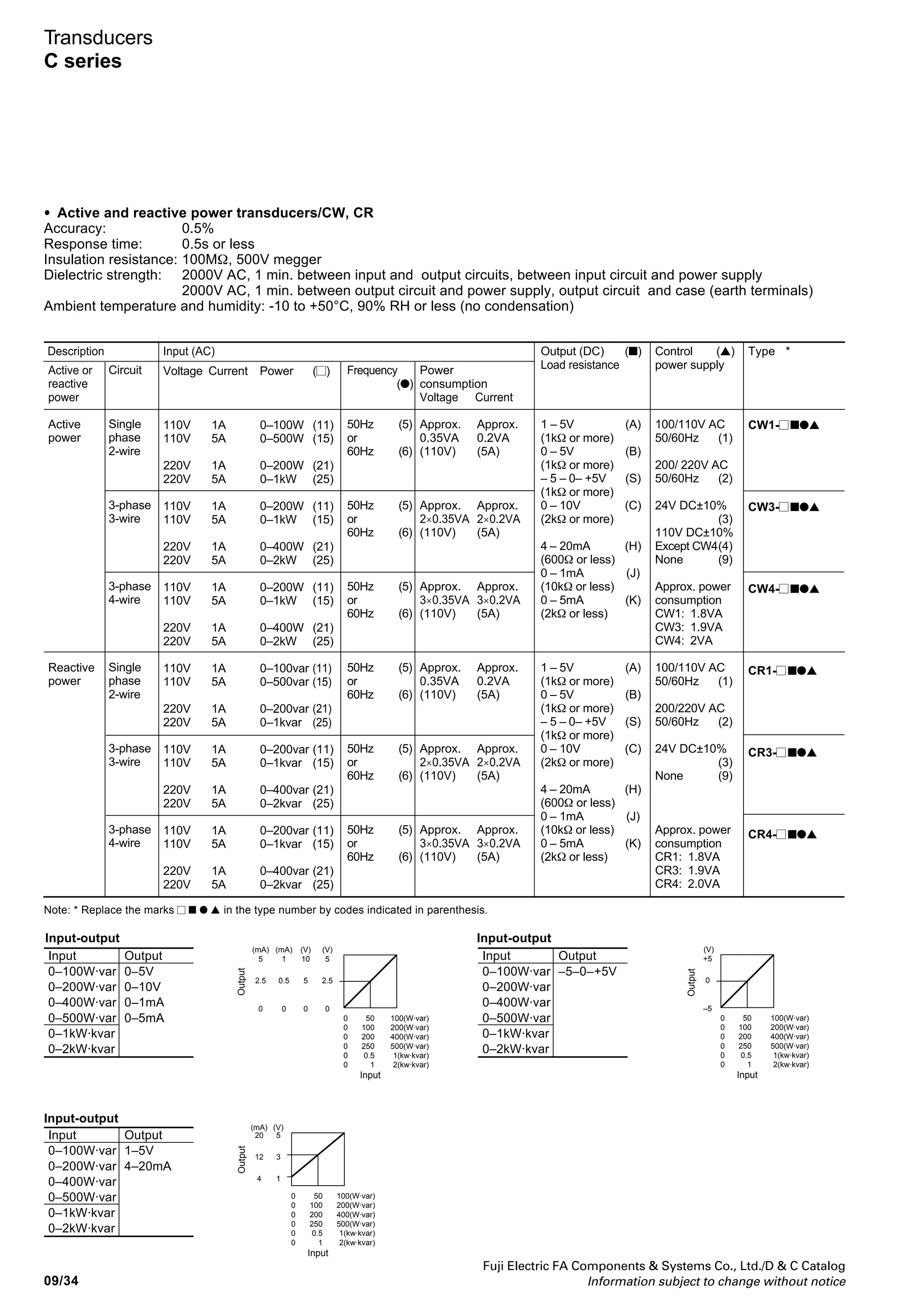
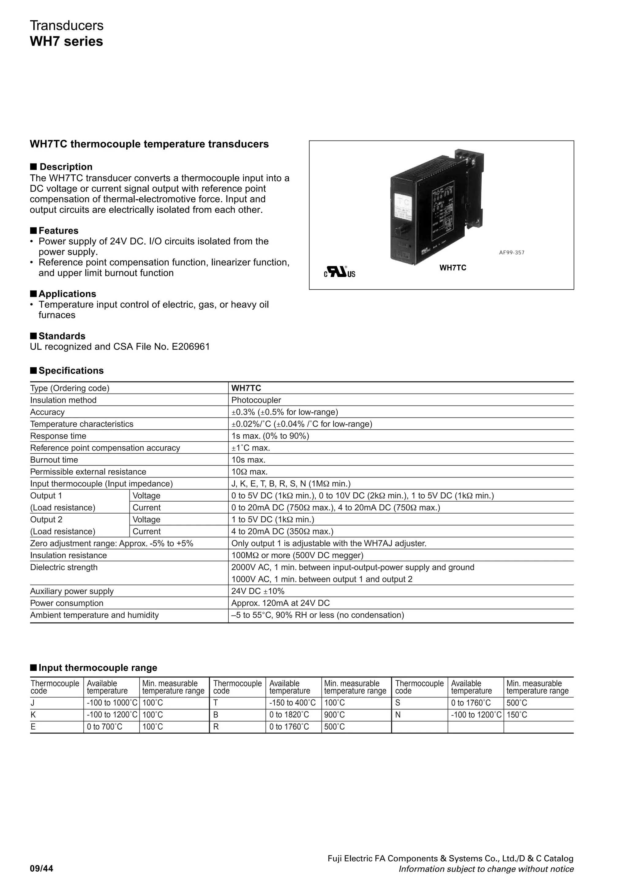
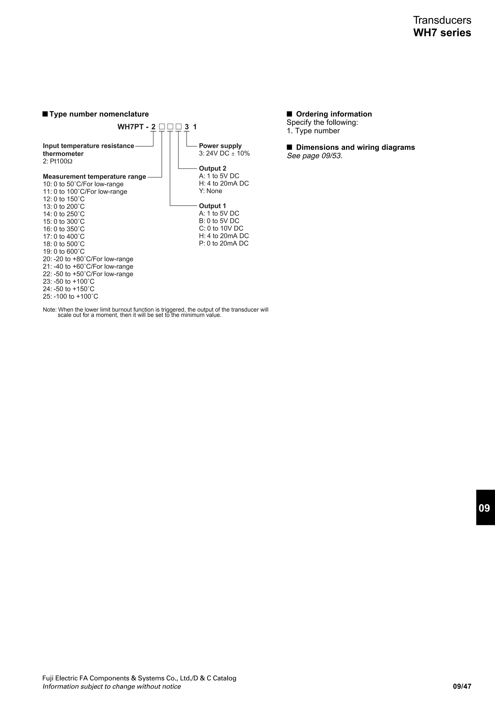
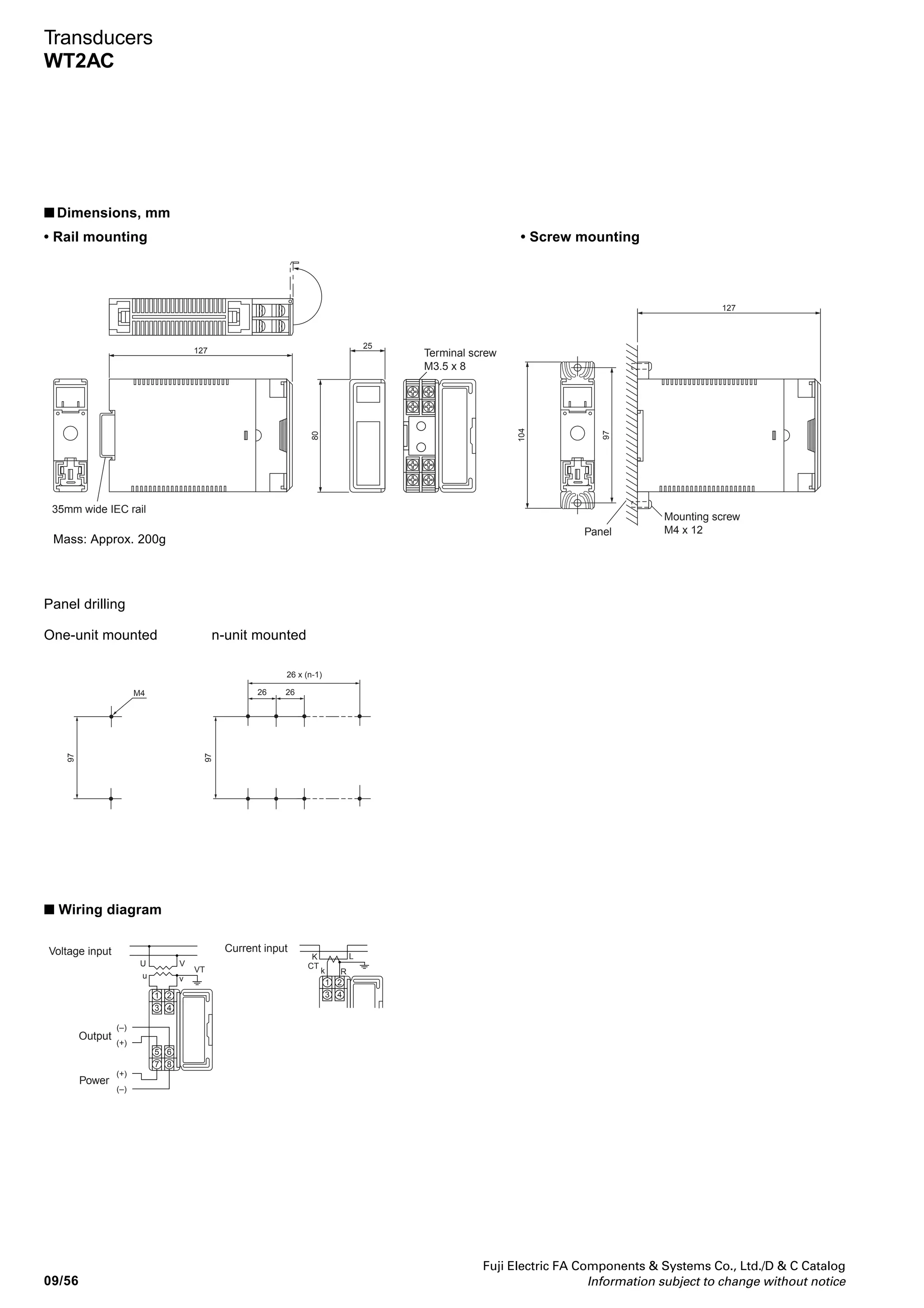
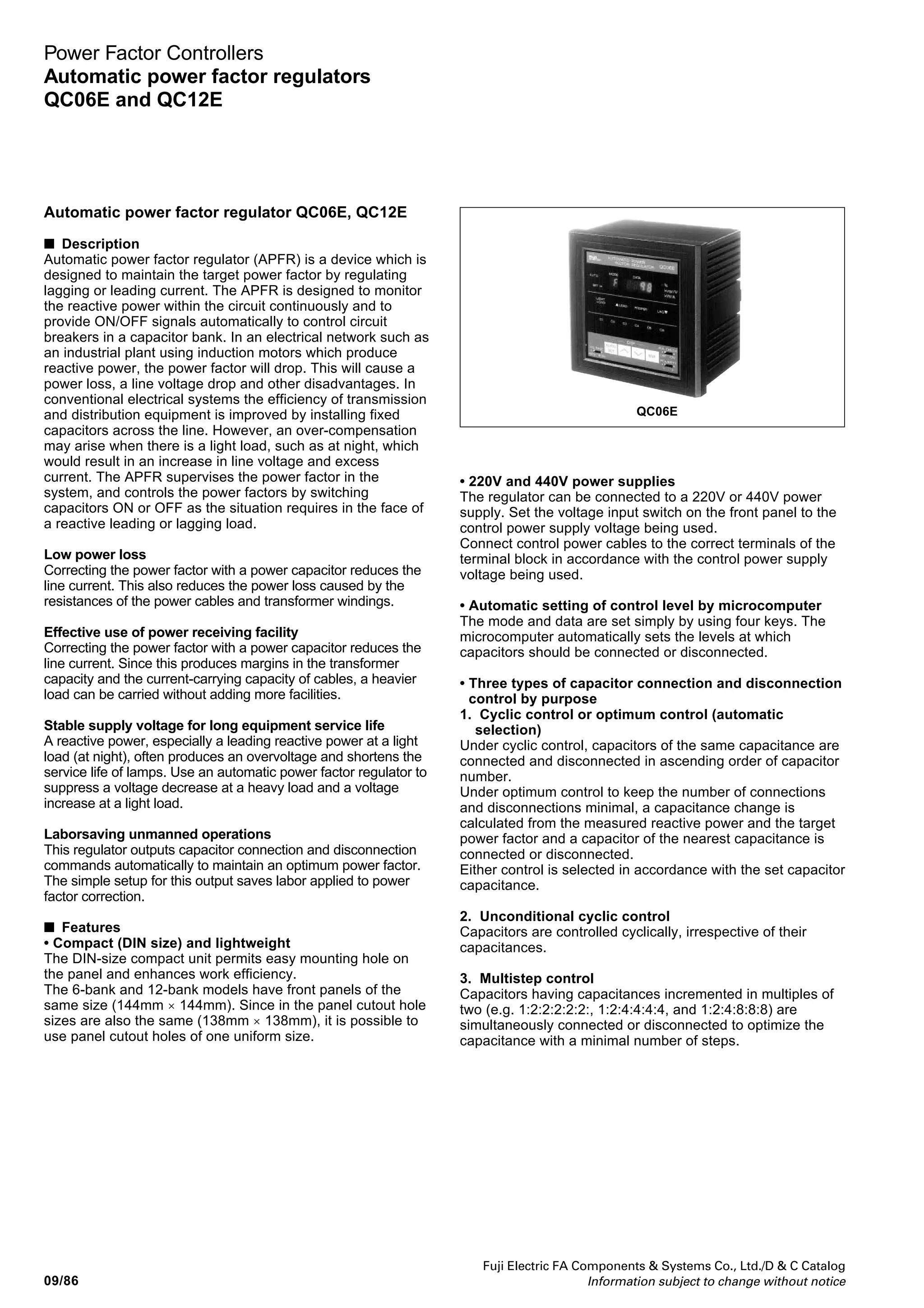
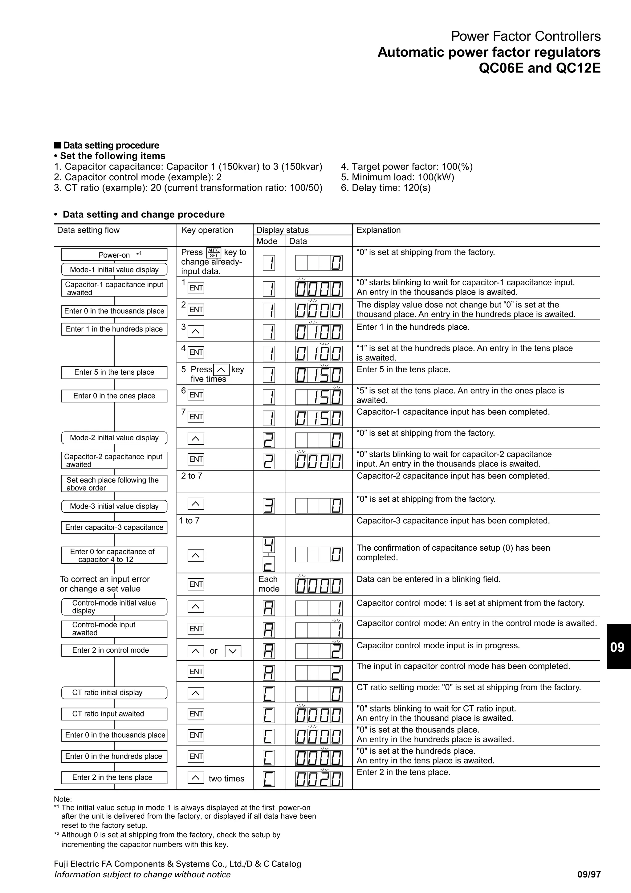
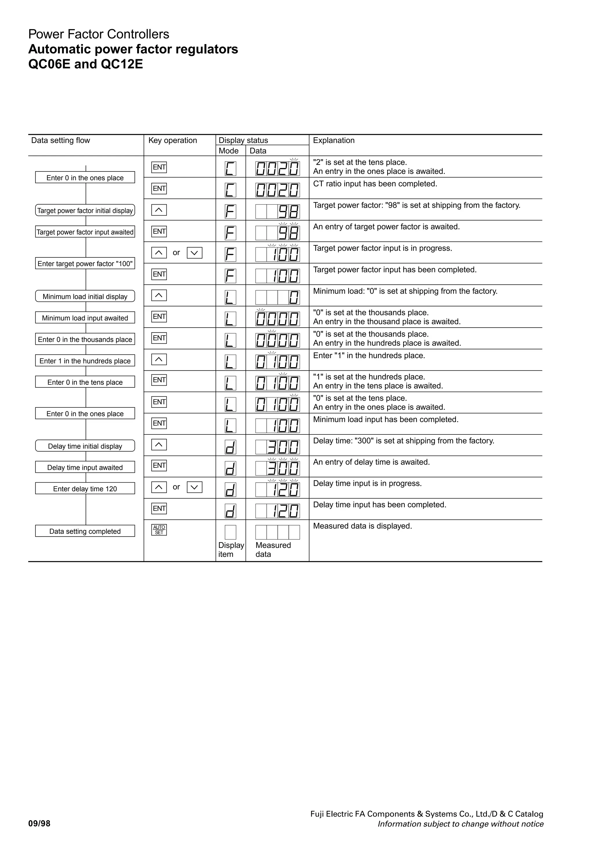
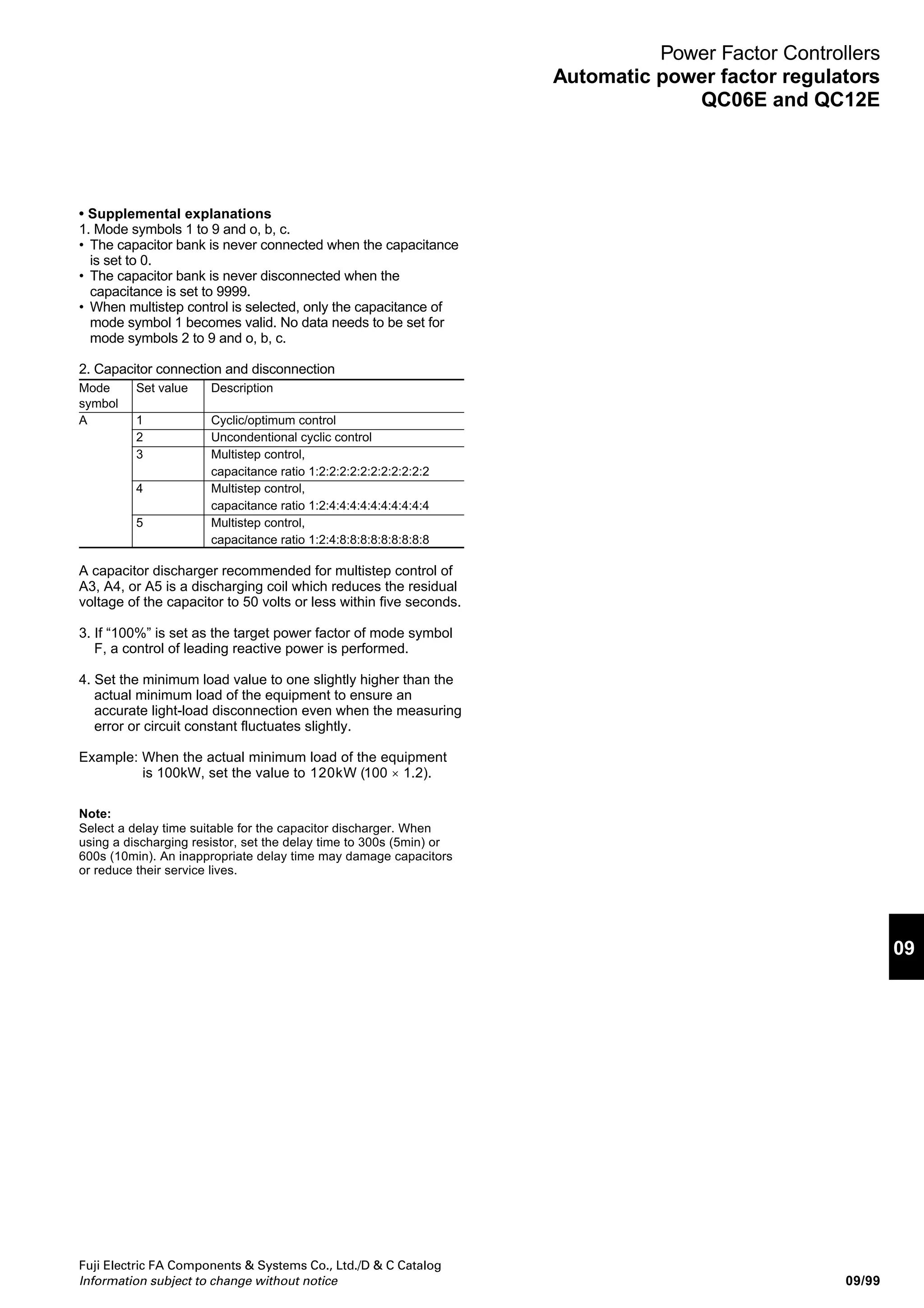
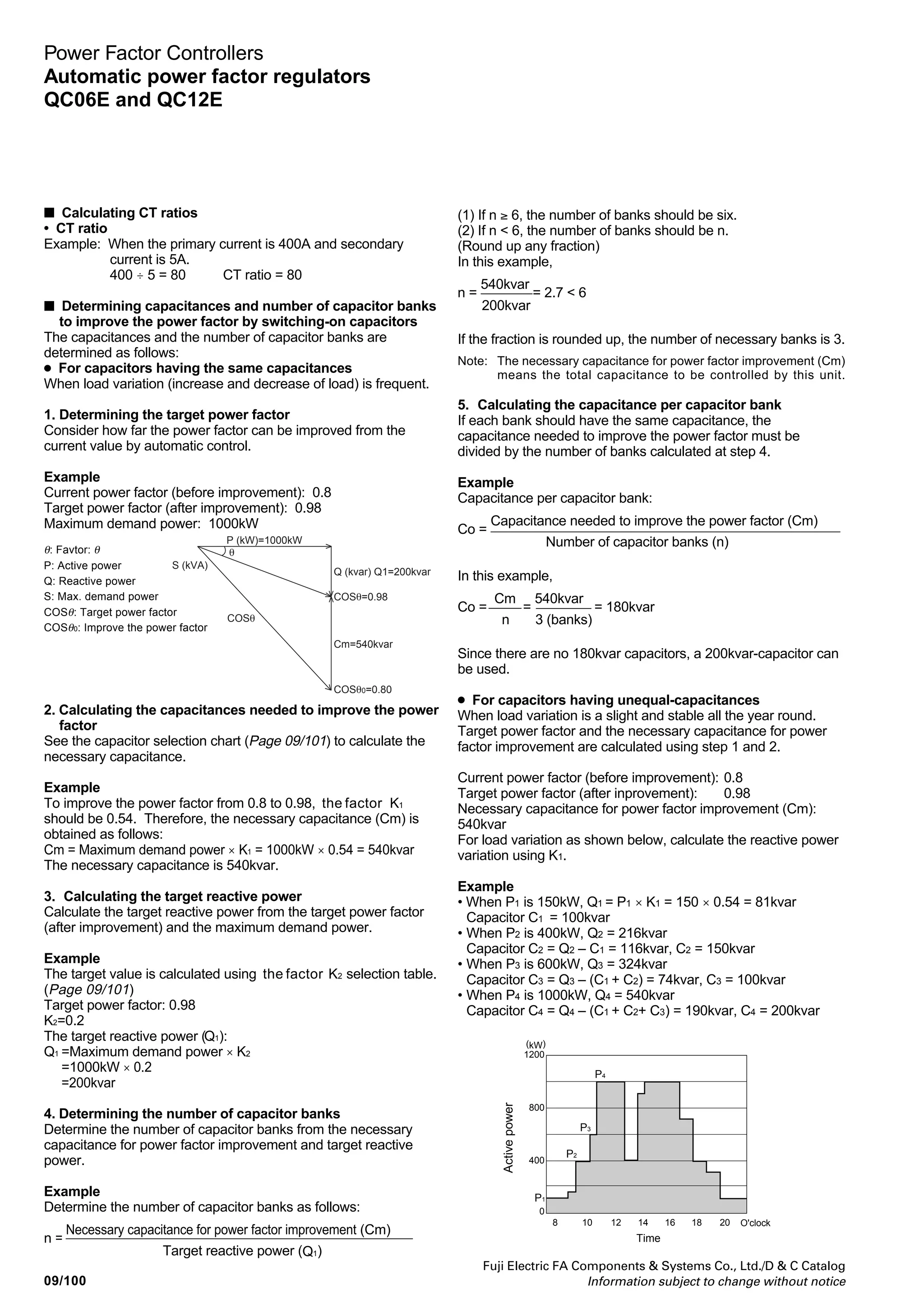
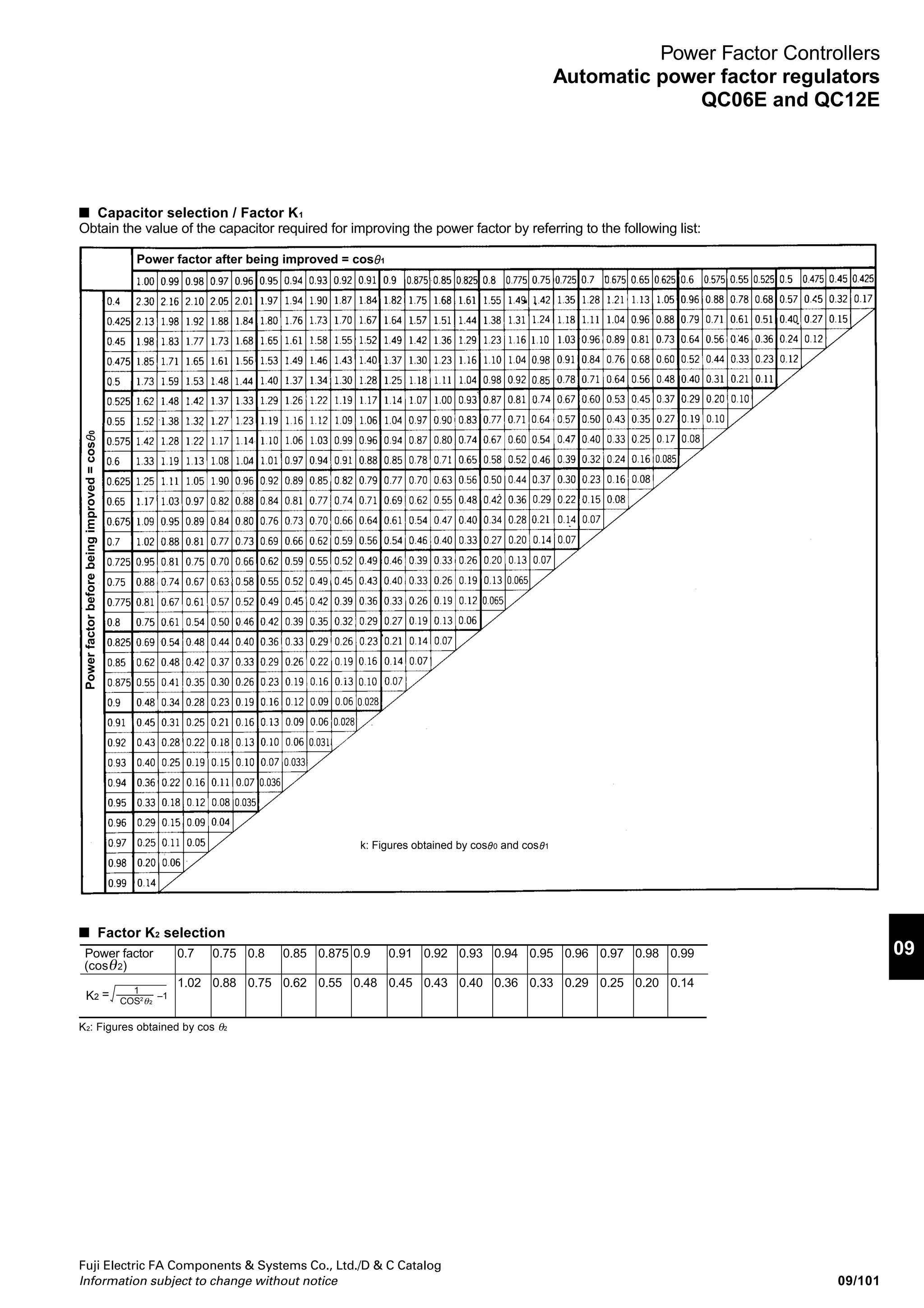
Power Factor Controllers
Automatic power factor regulators
QC06E and QC12E
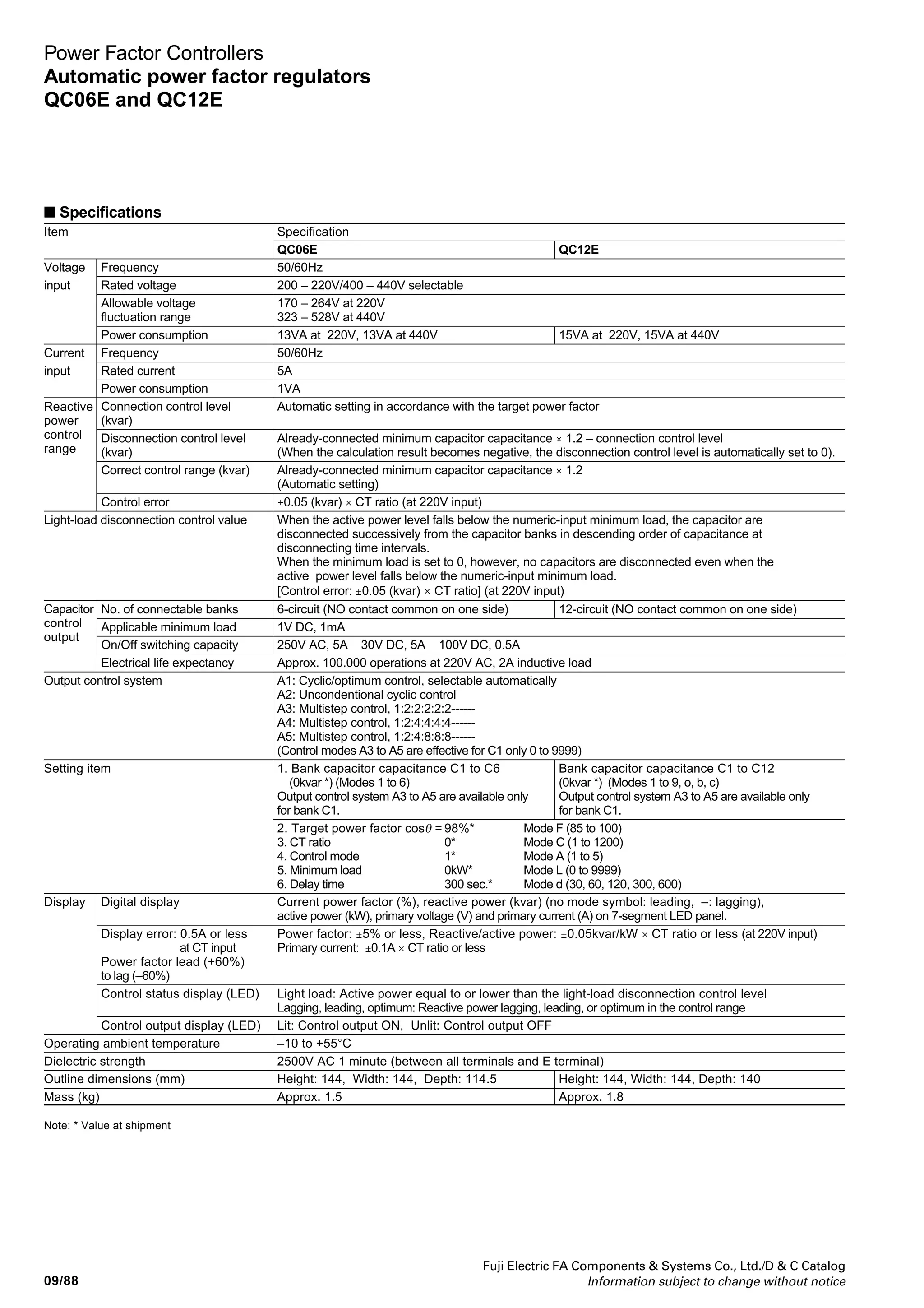
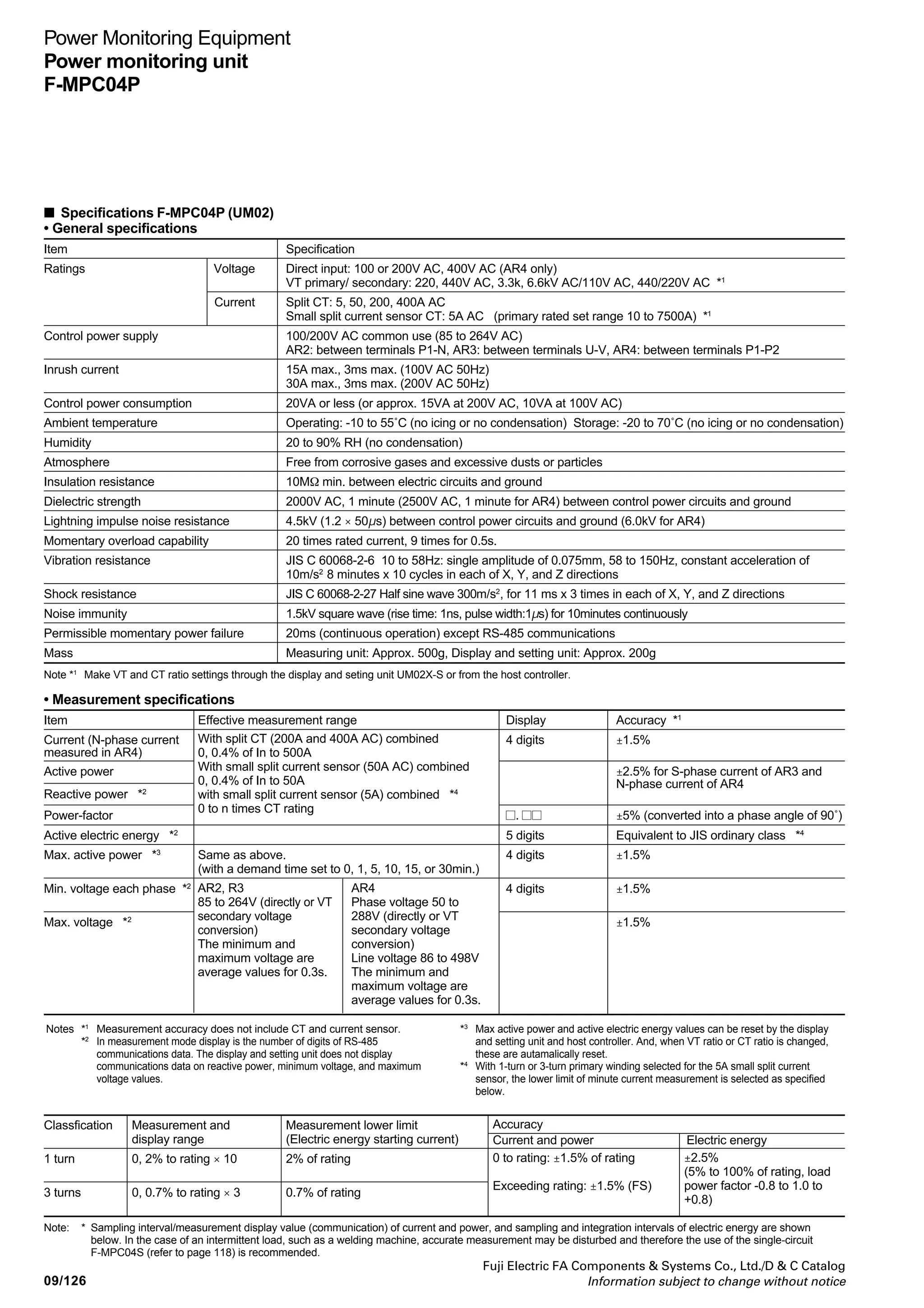
■ Specifications
Item Specification
QC06E QC12E
Voltage Frequency 50/60Hz
input Rated voltage 200 – 220V/400 – 440V selectable
Allowable voltage 170 – 264V at 220V
fluctuation range 323 – 528V at 440V
Power consumption 13VA at 220V, 13VA at 440V 15VA at 220V, 15VA at 440V
Current Frequency 50/60Hz
input Rated current 5A
Power consumption 1VA
Connection control level Automatic setting in accordance with the target power factor
(kvar)
Disconnection control level Already-connected minimum capacitor capacitance × 1.2 – connection control level
(kvar) (When the calculation result becomes negative, the disconnection control level is automatically set to 0).
Correct control range (kvar) Already-connected minimum capacitor capacitance × 1.2
(Automatic setting)
Control error ±0.05 (kvar) × CT ratio (at 220V input)
Light-load disconnection control value When the active power level falls below the numeric-input minimum load, the capacitor are
disconnected successively from the capacitor banks in descending order of capacitance at
disconnecting time intervals.
When the minimum load is set to 0, however, no capacitors are disconnected even when the
active power level falls below the numeric-input minimum load.
[Control error: ±0.05 (kvar) × CT ratio] (at 220V input)
No. of connectable banks 6-circuit (NO contact common on one side) 12-circuit (NO contact common on one side)
Applicable minimum load 1V DC, 1mA
On/Off switching capacity 250V AC, 5A 30V DC, 5A 100V DC, 0.5A
Electrical life expectancy Approx. 100.000 operations at 220V AC, 2A inductive load
Output control system A1: Cyclic/optimum control, selectable automatically
A2: Uncondentional cyclic control
A3: Multistep control, 1:2:2:2:2:2------
A4: Multistep control, 1:2:4:4:4:4------
A5: Multistep control, 1:2:4:8:8:8------
(Control modes A3 to A5 are effective for C1 only 0 to 9999)
Setting item 1. Bank capacitor capacitance C1 to C6 Bank capacitor capacitance C1 to C12
(0kvar *) (Modes 1 to 6) (0kvar *) (Modes 1 to 9, o, b, c)
Output control system A3 to A5 are available only Output control system A3 to A5 are available only
for bank C1. for bank C1.
2. Target power factor cosθ = 98%* Mode F (85 to 100)
3. CT ratio 0* Mode C (1 to 1200)
4. Control mode 1* Mode A (1 to 5)
5. Minimum load 0kW* Mode L (0 to 9999)
6. Delay time 300 sec.* Mode d (30, 60, 120, 300, 600)
Display Digital display Current power factor (%), reactive power (kvar) (no mode symbol: leading, –: lagging),
active power (kW), primary voltage (V) and primary current (A) on 7-segment LED panel.
Display error: 0.5A or less Power factor: ±5% or less, Reactive/active power: ±0.05kvar/kW × CT ratio or less (at 220V input)
at CT input Primary current: ±0.1A × CT ratio or less
Power factor lead (+60%)
to lag (–60%)
Control status display (LED) Light load: Active power equal to or lower than the light-load disconnection control level
Lagging, leading, optimum: Reactive power lagging, leading, or optimum in the control range
Control output display (LED) Lit: Control output ON, Unlit: Control output OFF
Operating ambient temperature –10 to +55°C
Dielectric strength 2500V AC 1 minute (between all terminals and E terminal)
Outline dimensions (mm) Height: 144, Width: 144, Depth: 114.5 Height: 144, Width: 144, Depth: 140
Mass (kg) Approx. 1.5 Approx. 1.8
Capacitor
control
output
Reactive
power
control
range
Note: * Value at shipment](https://image.slidesharecdn.com/dec2009-measuringinstuments-141201203626-conversion-gate01/75/09-Measuring-Instuments-Fuji-Electric-92-2048.jpg)
![Fuji Electric FA Components Systems Co., Ltd./D C Catalog
Information subject to change without notice
09
09/91
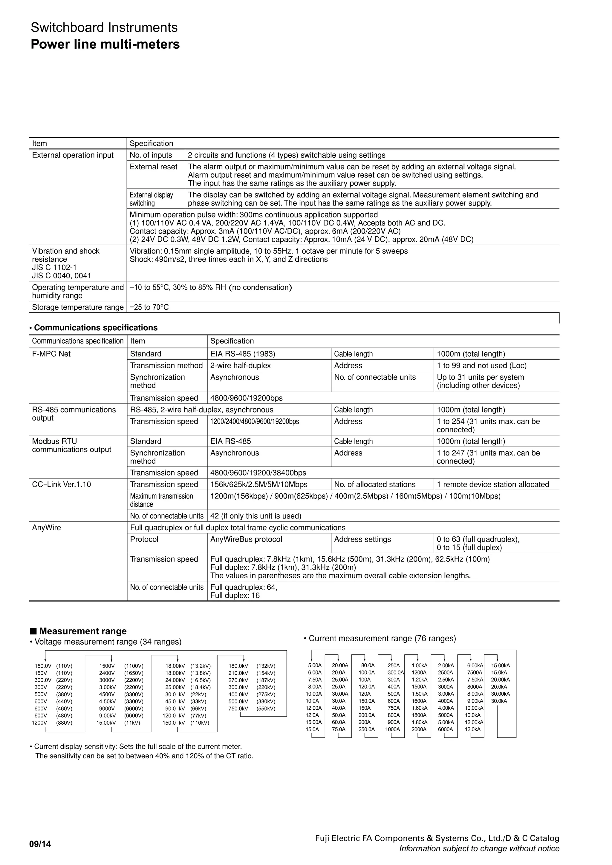
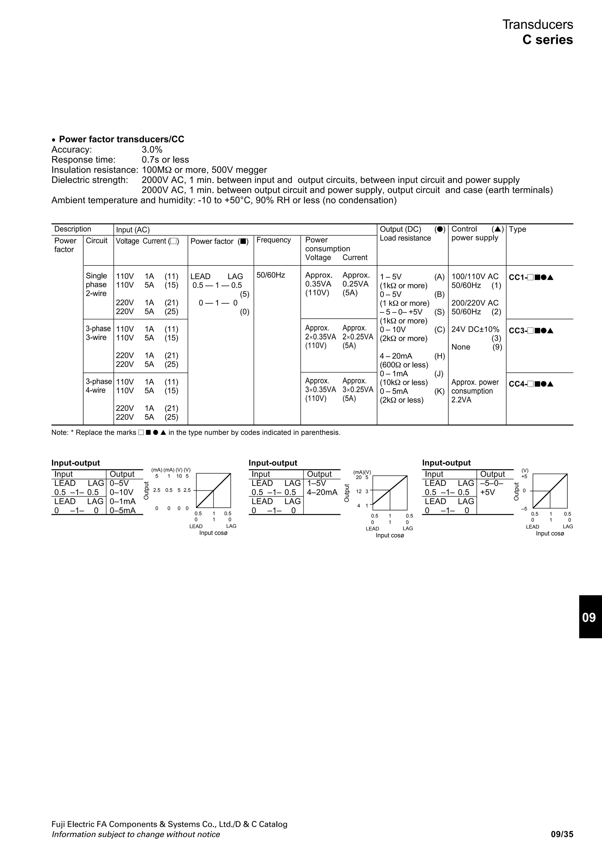
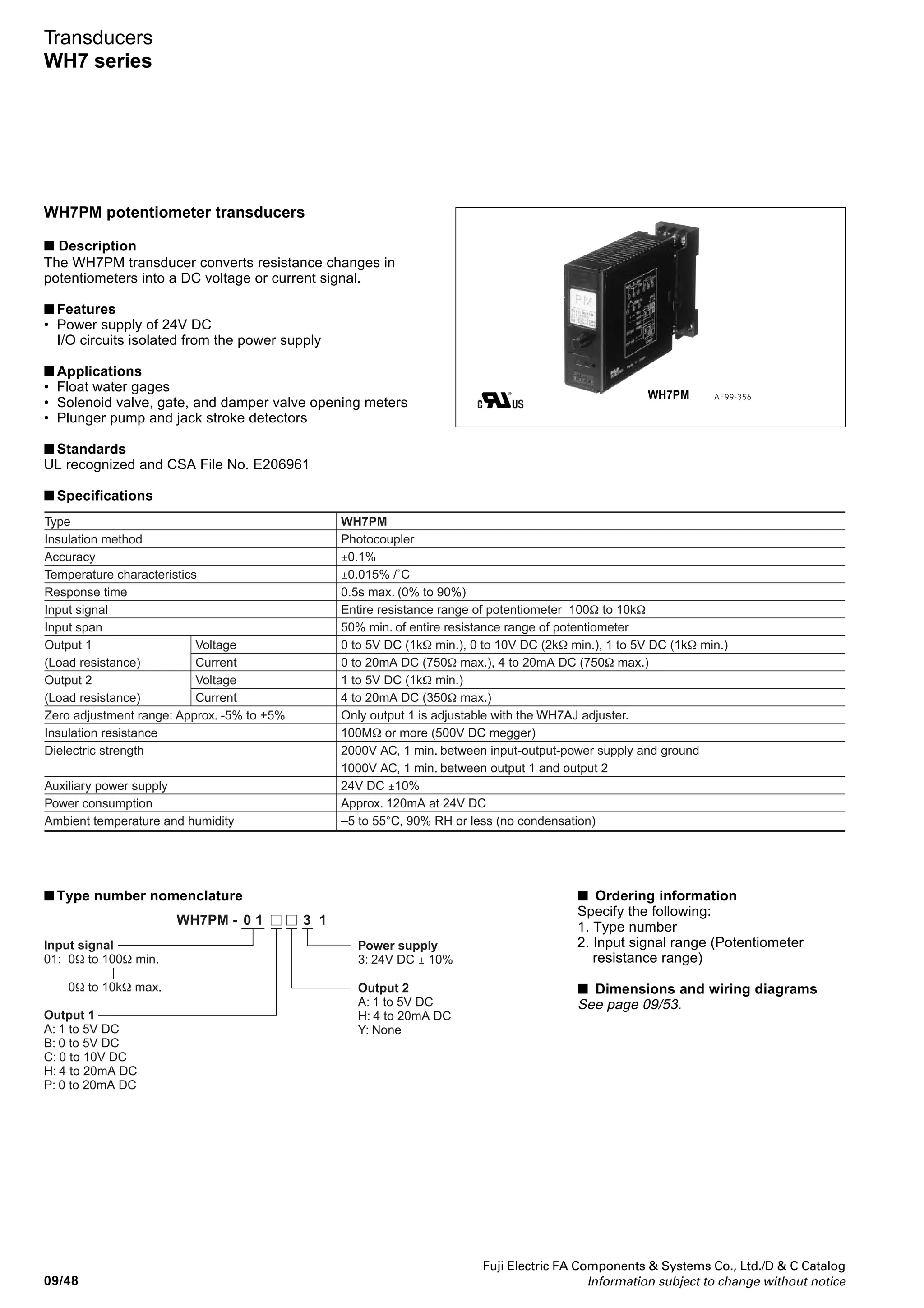
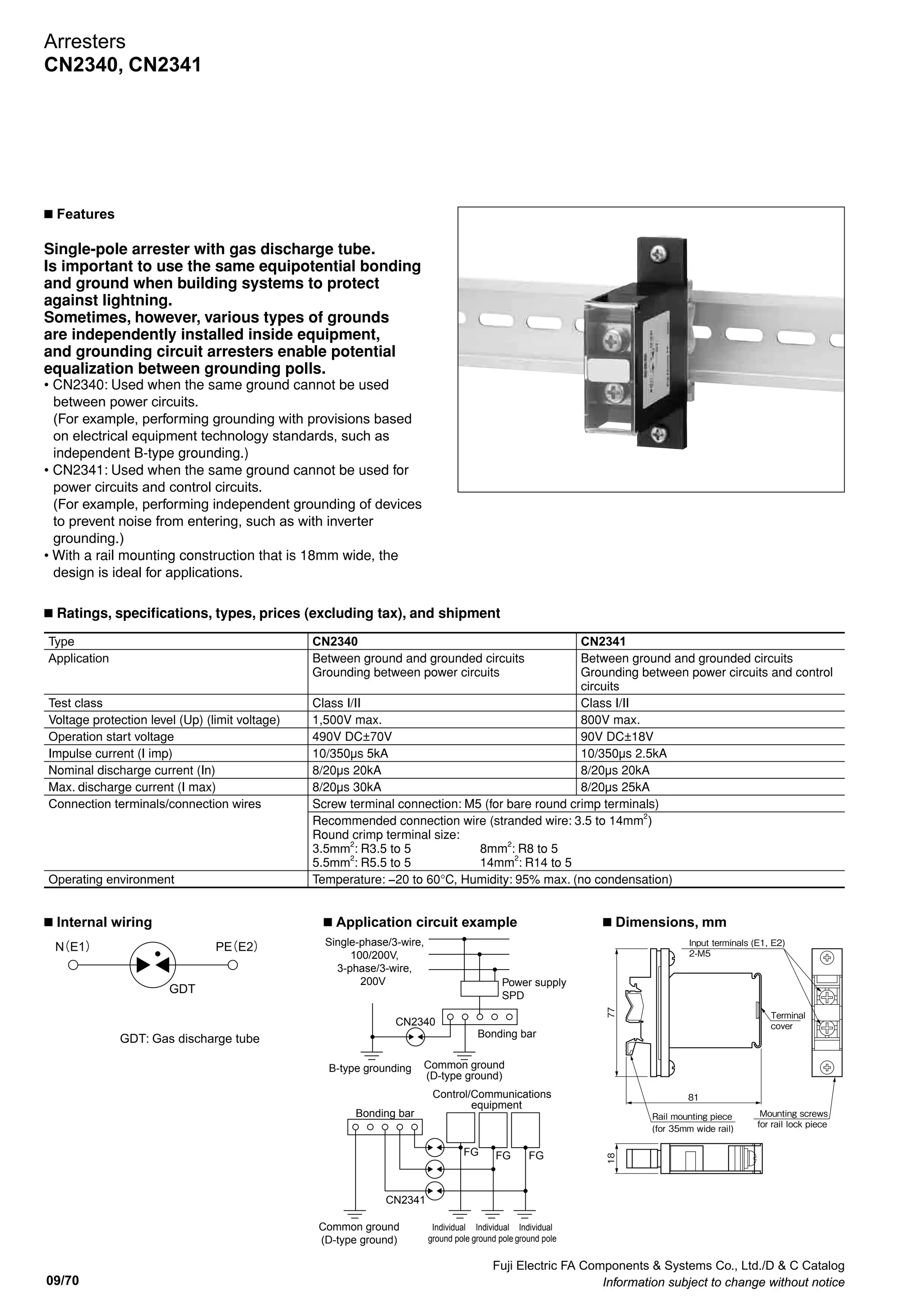
Power Factor Controllers
Automatic power factor regulators
QC06E and QC12E
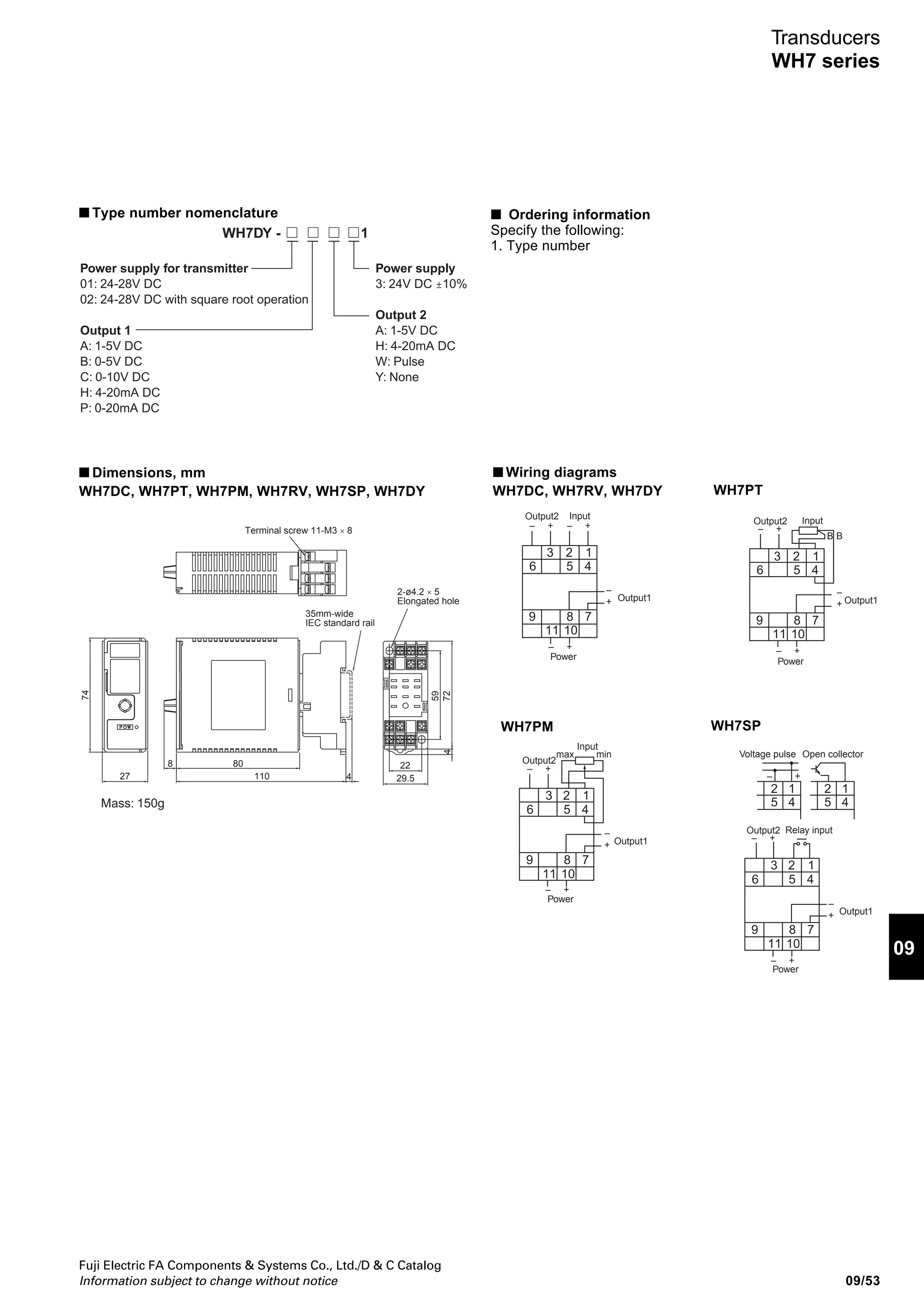
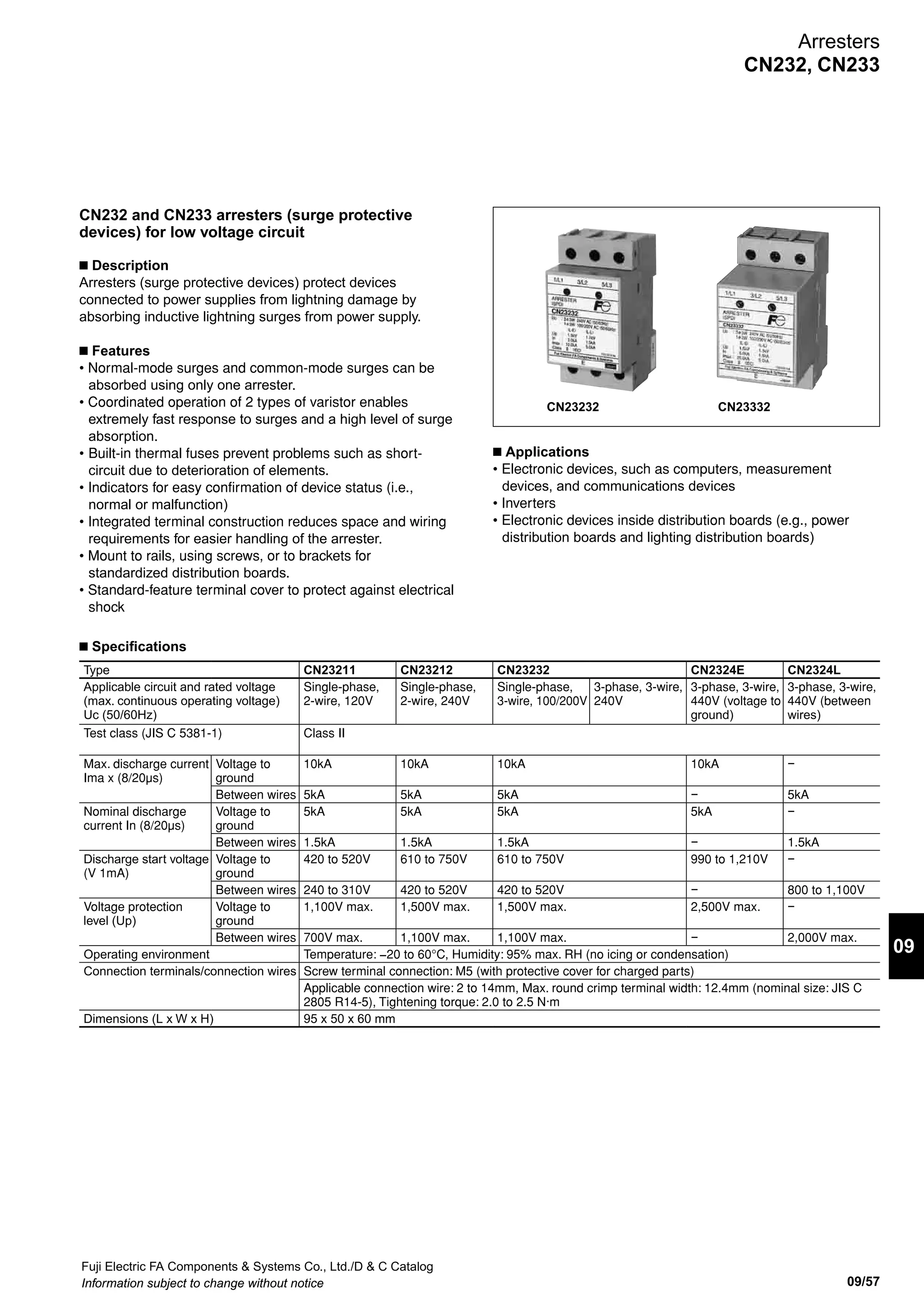
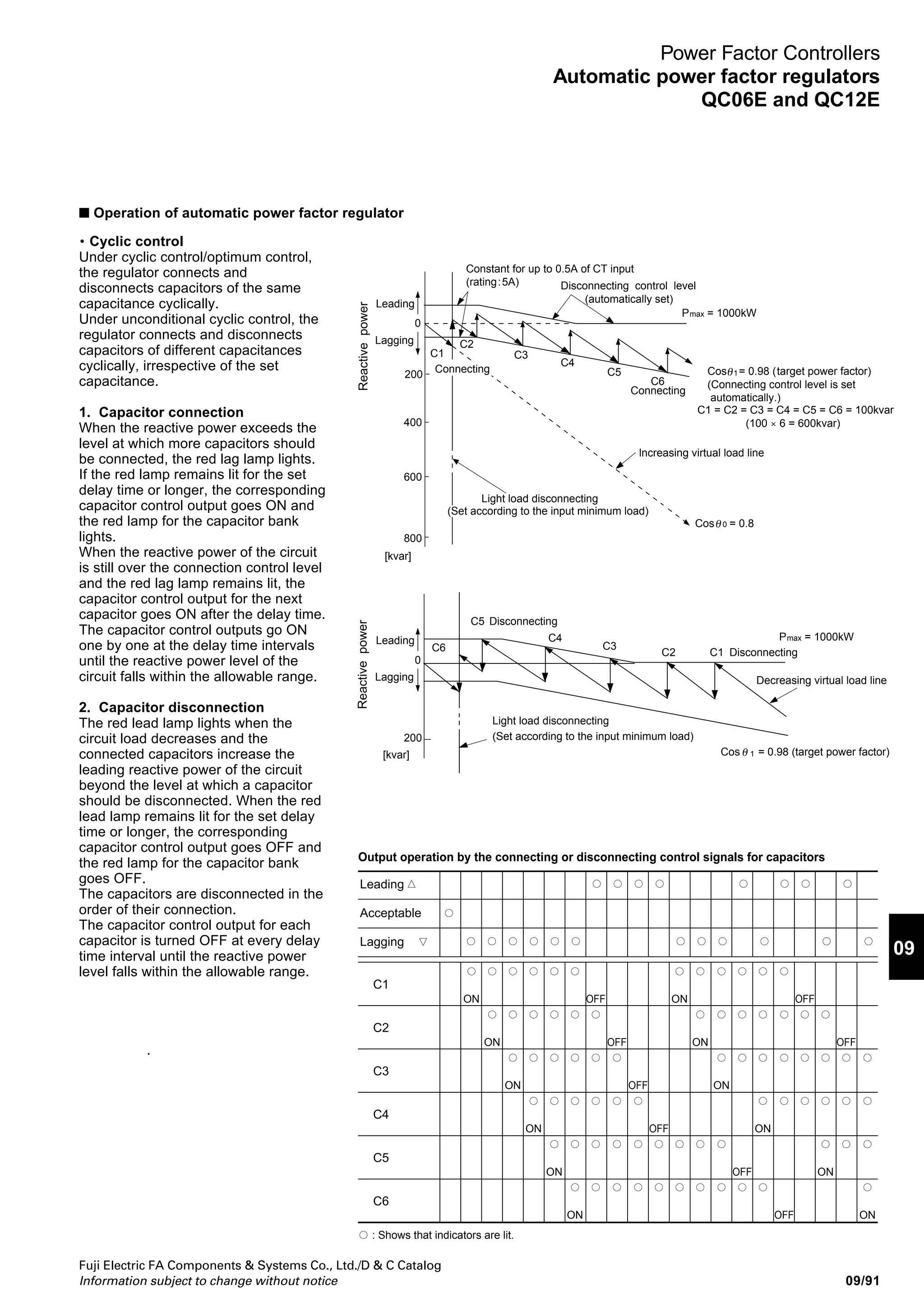
• Cyclic control
Under cyclic control/optimum control,
the regulator connects and
disconnects capacitors of the same
capacitance cyclically.
Under unconditional cyclic control, the
regulator connects and disconnects
capacitors of different capacitances
cyclically, irrespective of the set
capacitance.
1. Capacitor connection
When the reactive power exceeds the
level at which more capacitors should
be connected, the red lag lamp lights.
If the red lamp remains lit for the set
delay time or longer, the corresponding
capacitor control output goes ON and
the red lamp for the capacitor bank
lights.
When the reactive power of the circuit
is still over the connection control level
and the red lag lamp remains lit, the
capacitor control output for the next
capacitor goes ON after the delay time.
The capacitor control outputs go ON
one by one at the delay time intervals
until the reactive power level of the
circuit falls within the allowable range.
2. Capacitor disconnection
The red lead lamp lights when the
circuit load decreases and the
connected capacitors increase the
leading reactive power of the circuit
beyond the level at which a capacitor
should be disconnected. When the red
lead lamp remains lit for the set delay
time or longer, the corresponding
capacitor control output goes OFF and
the red lamp for the capacitor bank
goes OFF.
The capacitors are disconnected in the
order of their connection.
The capacitor control output for each
capacitor is turned OFF at every delay
time interval until the reactive power
level falls within the allowable range.
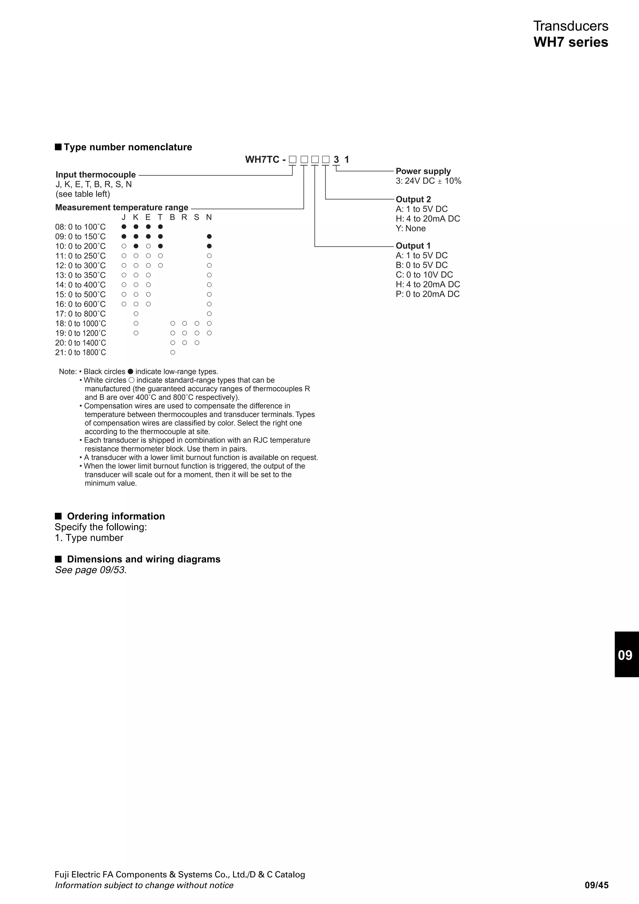
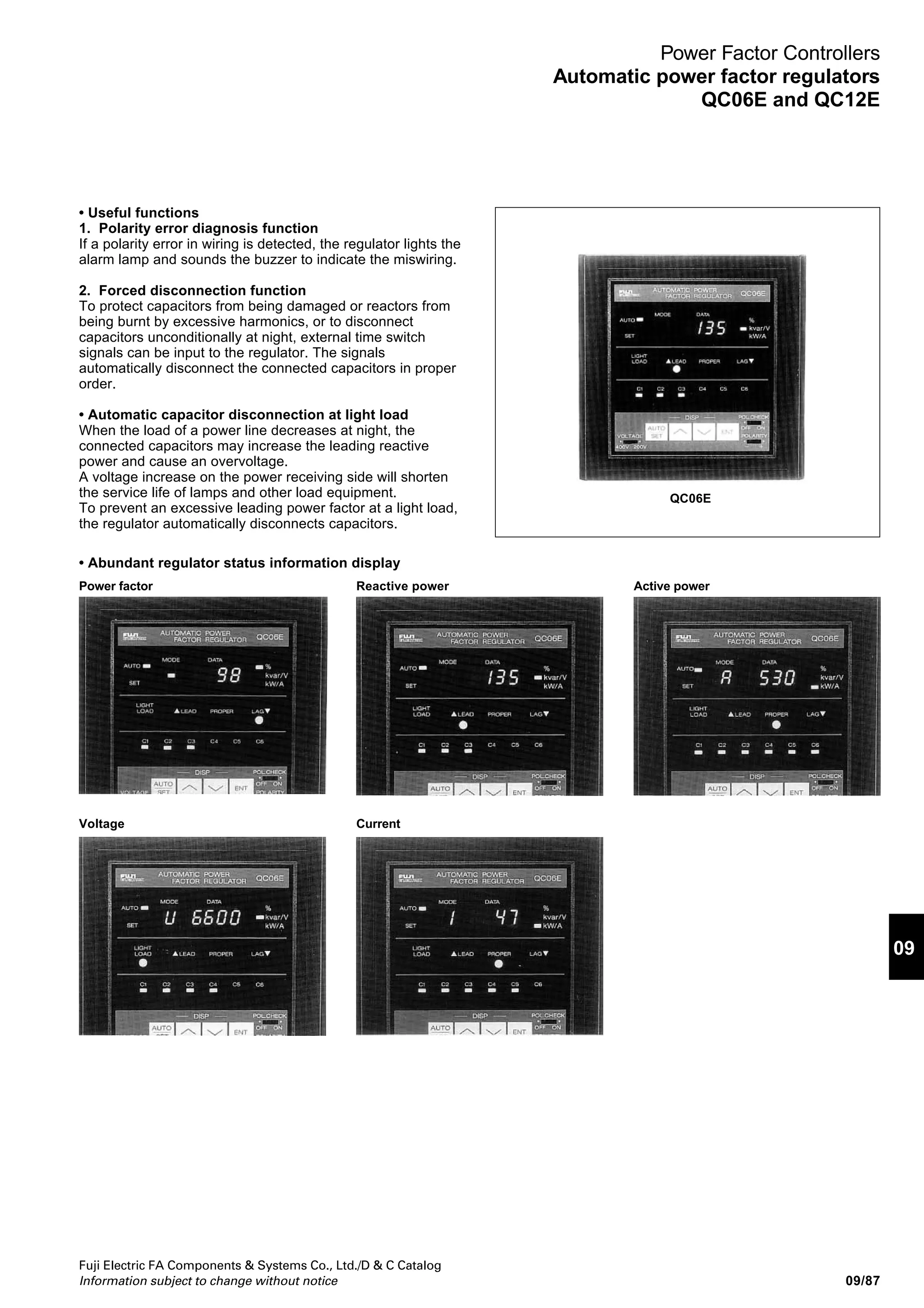
■ Operation of automatic power factor regulator
Constant for up to 0.5A of CT input
(rating:5A) Disconnecting control level
(automatically set)
P = 1000kW
P = 1000kW
Cos = 0.98 (target power factor)
(Connecting control level is set
automatically.)
C1 = C2 = C3 = C4 = C5 = C6 = 100kvar
(100 × 6 = 600kvar)
C1
C1
C2
C2
C3
C3
C4
C4
C5
C5
C6
C6
Connecting
Connecting
lncreasing virtual load line
Cos = 0.8
Cos = 0.98 (target power factor)
Light load disconnecting
Light load disconnecting
(Set according to the input minimum load)
(Set according to the input minimum load)
0
0
200
200
400
600
800
Lagging
Leading
ReactivepowerReactivepower
Disconnecting
Disconnecting
Decreasing virtual load line
max
max
1
0
[kvar]
[kvar]
1
θ
θ
θ
Lagging
Leading
Output operation by the connecting or disconnecting control signals for capacitors
C1
C2
C3
C4
C5
C6
ON
OFF
ON
OFF
ON
OFF
OFF
ON
ON
ON
ON
OFF
OFF
OFF
OFF
ON
ON
ON
ON
ON
Leading
Acceptable
Lagging
: Shows that indicators are lit.](https://image.slidesharecdn.com/dec2009-measuringinstuments-141201203626-conversion-gate01/75/09-Measuring-Instuments-Fuji-Electric-95-2048.jpg)
![Fuji Electric FA Components Systems Co., Ltd./D C Catalog
Information subject to change without notice09/92
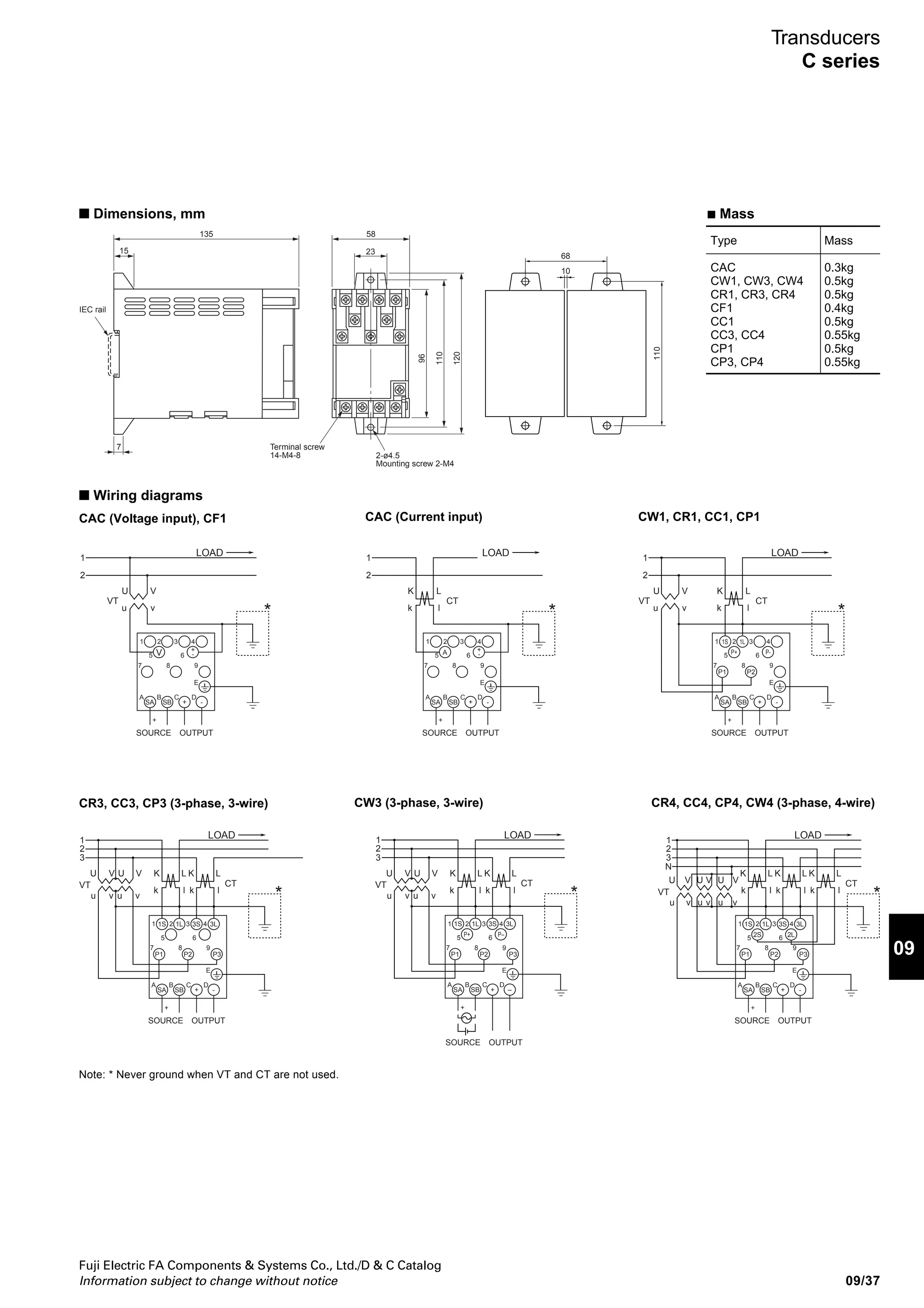
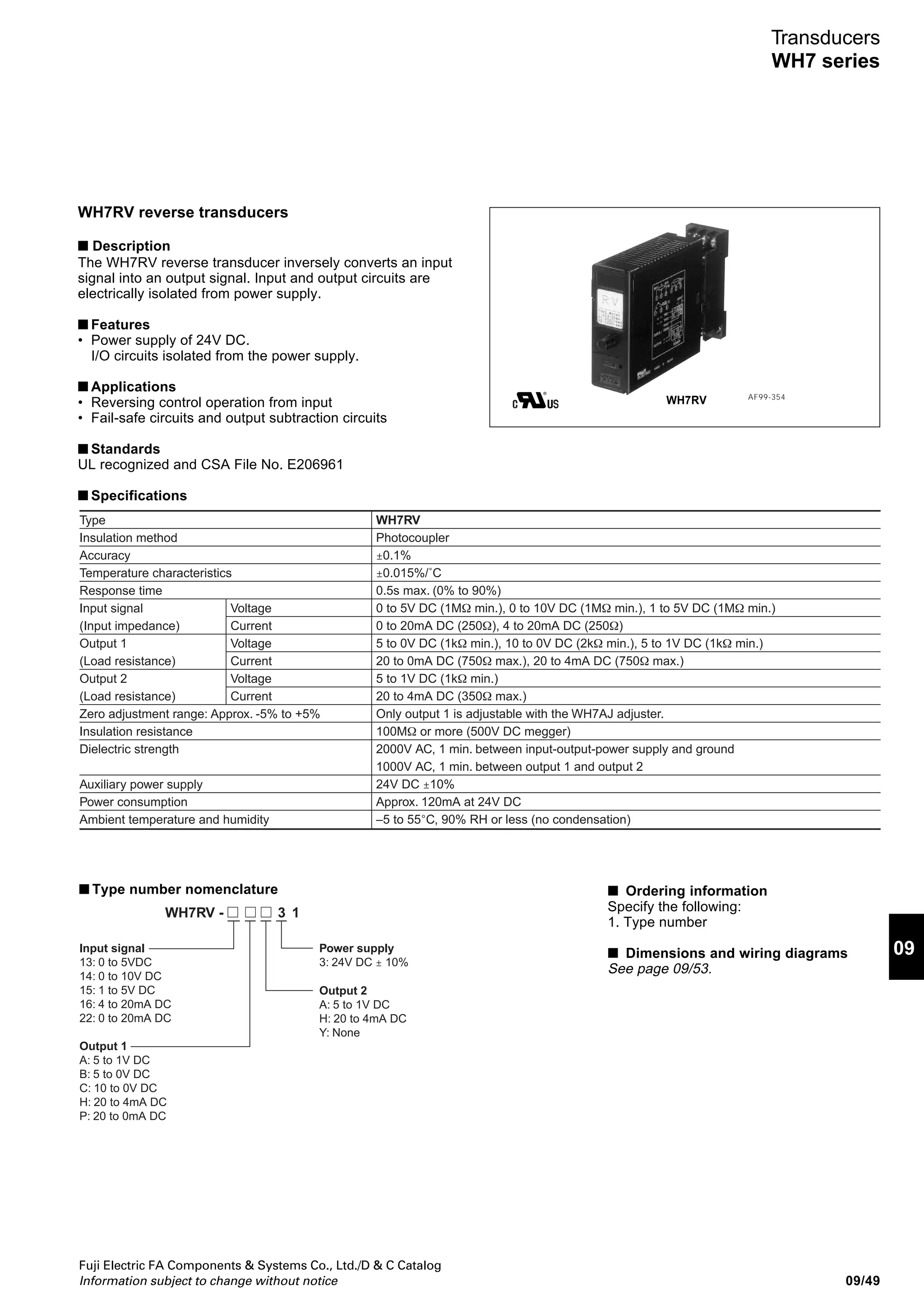
Power Factor Controllers
Automatic power factor regulators
QC06E and QC12E
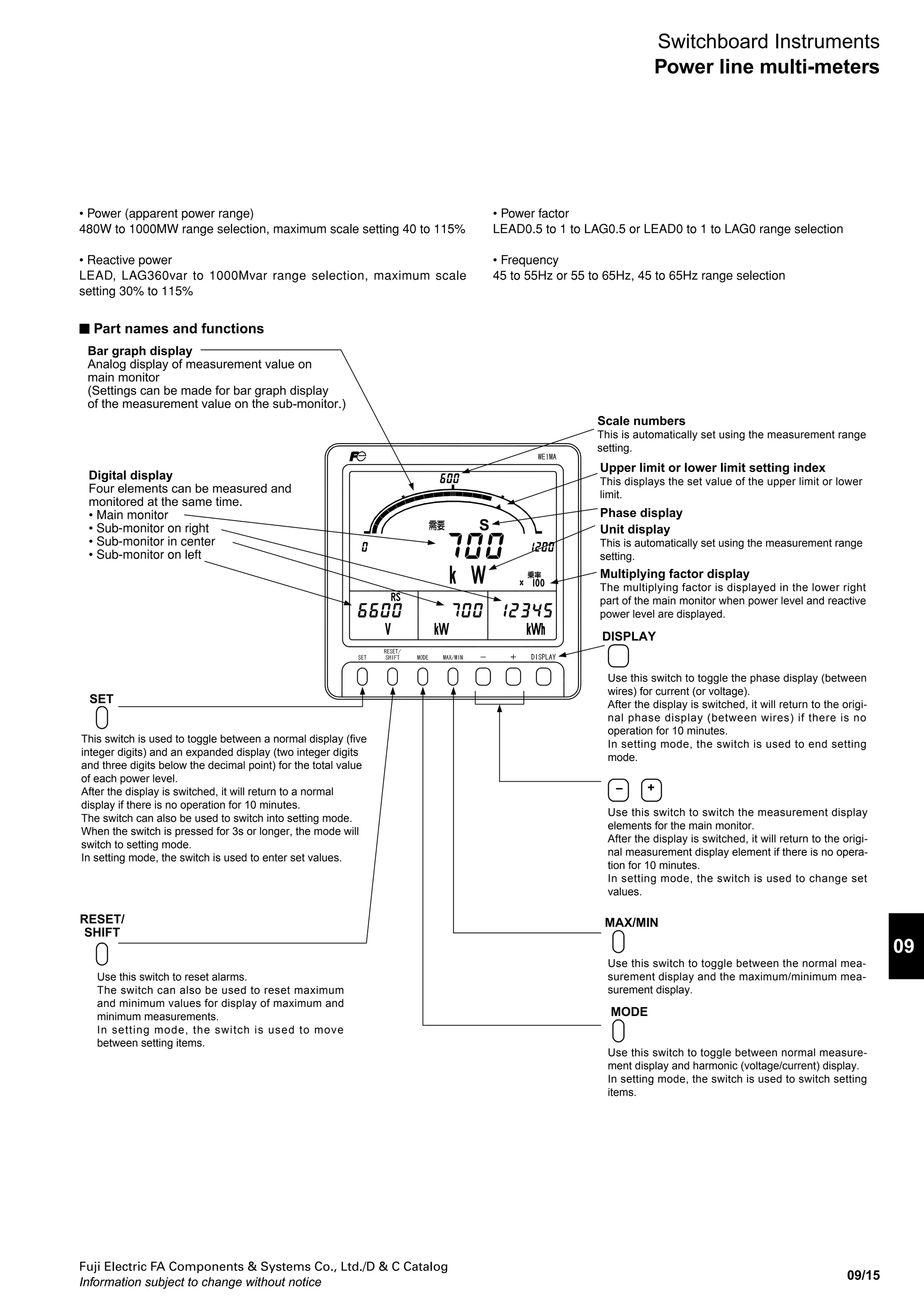
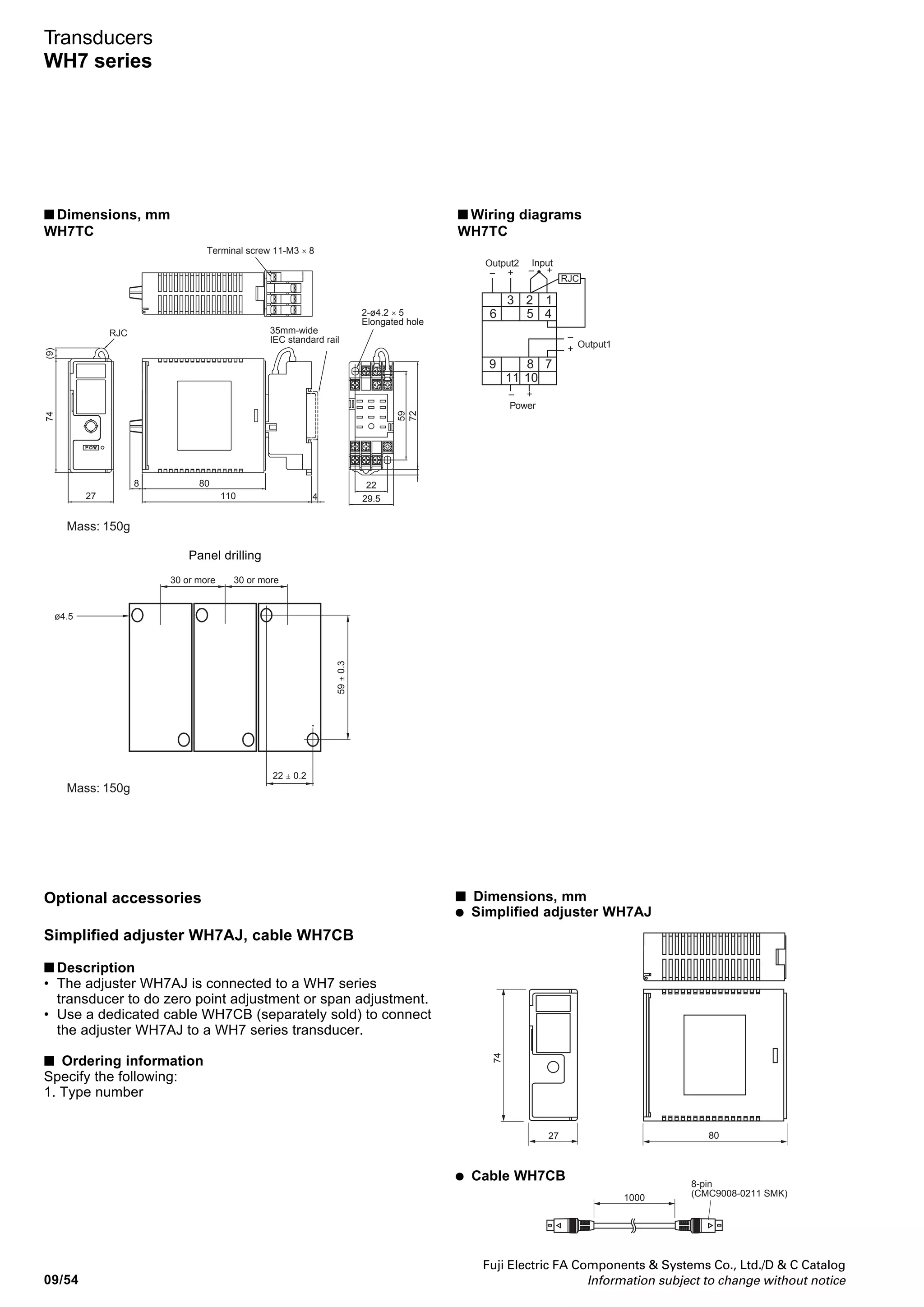
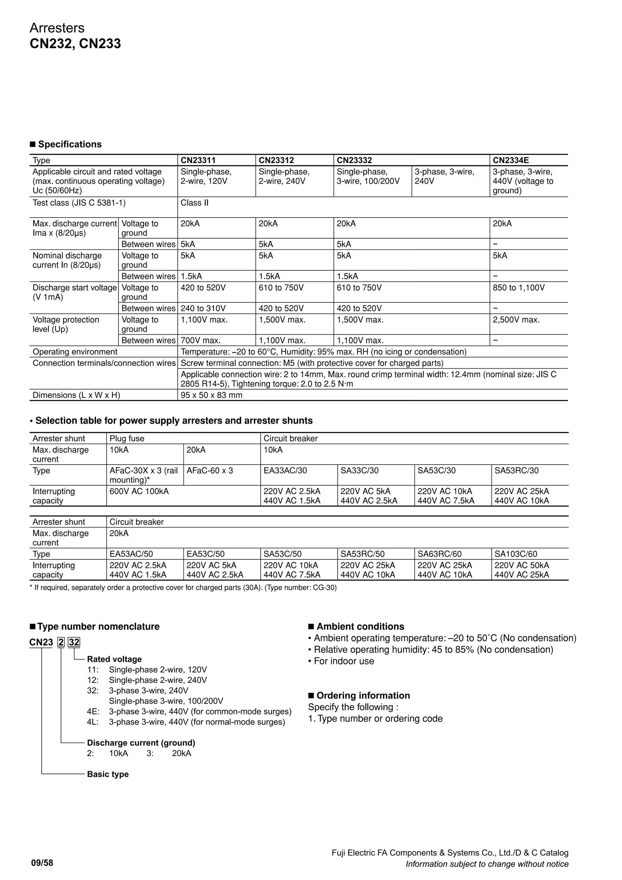
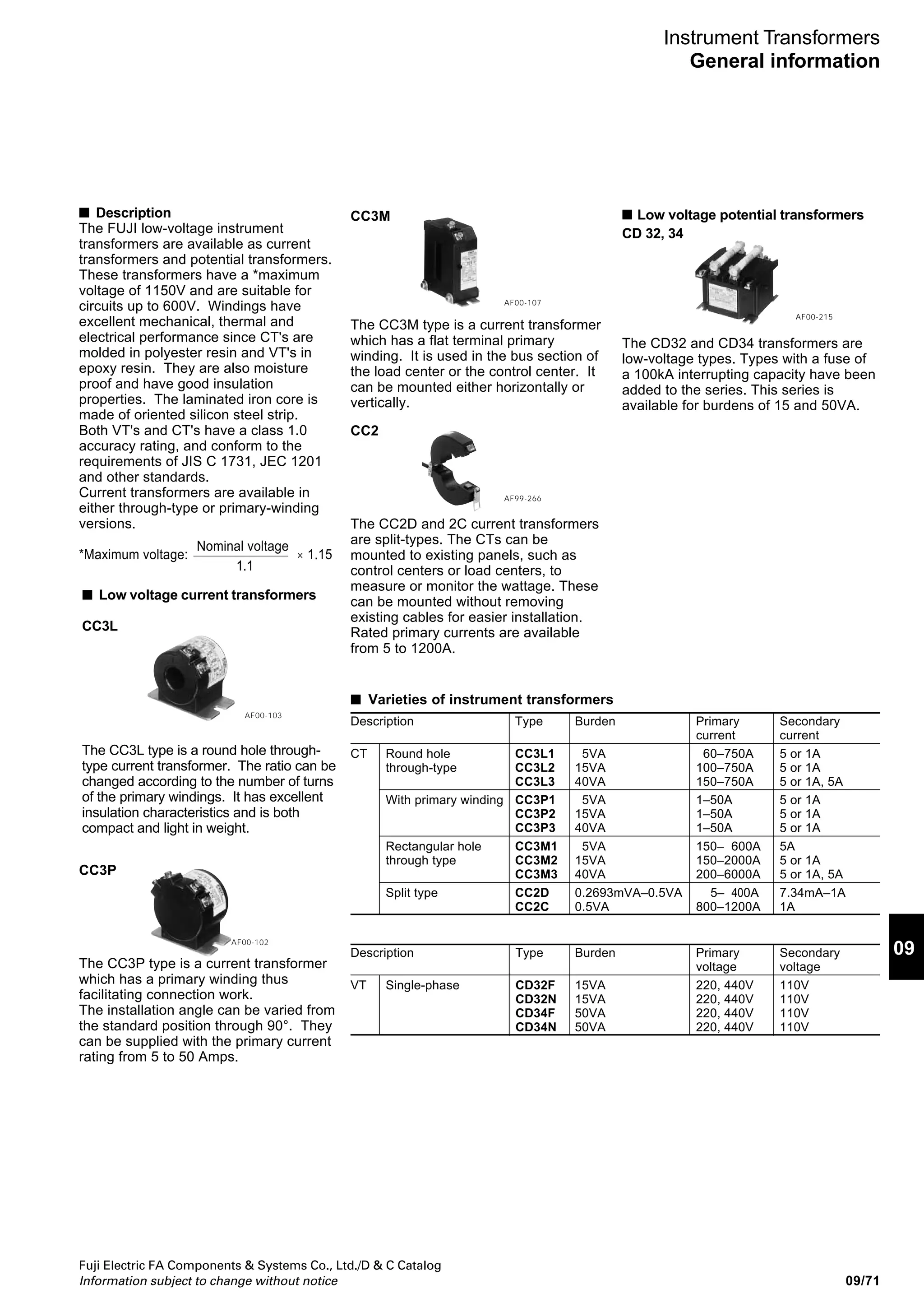
• Optimum control
Under optimum control, the regulator
connects or disconnects the capacitor
with the capacitance closest to the
change of reactive power among
capacitors of different capacitances. If
there are two or more capacitors of the
same capacitance, the regulator
connects or disconnects the capacitors
cyclically for optimum control (the
number of switchings) match.
1. Capacitor connection
The red lag lamp lights when the
reactive power level exceeds the level
at which more capacitors should be
connected. The regulator calculates
the difference between the current
reactive power and the level at which
more capacitors should be connected,
and integrates the calculated value for
the set delay time. The average value
per unit time is calculated from the
integrated total and a capacitor having
the capacitance closest to the average
value is selected. The capacitor control
output for the capacitor is turned ON
and the red lamp of the capacitor bank
lights.
The regulator continues integrating
and averaging the differences between
the current reactive power level and
the level at which more capacitors
should be connected, and selecting
optimum capacitors. The capacitor
control output is turned ON repeatedly
until the reactive power of the circuit
falls within the allowable range.
Figure 1 shows an example of a
capacitor connection control with a
load variation pattern.
2. Capacitor disconnection
When the circuit load decreases, the
already-connected capacitors increase
the leading reactive power level. If the
reactive power level exceeds the level
at which capacitors should be
disconnected, the red lead lamp lights.
The regulator calculates the difference
between the current reactive power
level and the level at which capacitors
should be disconnected, and
integrates the calculated value for the
set delay time. The average value per
unit time is calculated from the
integrated total and a capacitor having
the capacitance closest to the average
value is selected. The capacitor control
output for the capacitor is turned OFF
and the red lamp of the capacitor bank
goes OFF.
The regulator continues integrating
and averaging the differences between
the current reactive power level and
the level at which capacitors should be
disconnected, and selecting optimum
capacitors. The capacitor control
1000
800
600
400
200
0
8 10 12 14 16 18 20 22 O'clock
8 10 12 14 16 18 20 22 O'clock
Vector diagram
Vector diagram
Loadcapacity
1000
800
600
400
200
0
Loadcapacity
0
200
400
600
800
Leading
0
200
400
Constant for up to 0.5A of CT input
rating :5A Disconnecting control level
Disconnecting Disconnecting control level
Decreasing virtual load line
(automatically set)
(automatically set)
P =1000kW
Cos =0.98(target power factor)
Cos = 0.98(target power factor)
(Connecting control level is set
automatically)
C1
Connecting
Connecting
C3 C2
C3
C1
C2
C4
C4
lncreasing virtual load line
Light load disconnecting
level
(Set according to the
input minimum load)
Light load disconnecting level
(Set according to the input minimum load)
Cos = 0.8
C1 = 100kvar
C2 = 100kvar
C3 = 150kvar
C4 = 200kvar
Total 550kvar
C1 = 100kvar
C2 = 100kvar
C3 = 150kvar
C4 = 200kvar
Total 550kvar
max
P =1000kW
1
0
[kW]
[kvar]
θ
1
Minimum
load
ReactivepowerReactivepower
Fig. 2
Fig. 1
Connecting
Lagging
max
θ
θ
[kW]
[kvar]
Leading
Lagging
Disconnecting
output is turned OFF repeatedly until
the reactive power level of the circuit
falls within the allowable range.
Figure 2 shows an example of
capacitor disconnection control with a
load variation pattern.](https://image.slidesharecdn.com/dec2009-measuringinstuments-141201203626-conversion-gate01/75/09-Measuring-Instuments-Fuji-Electric-96-2048.jpg)
![Fuji Electric FA Components Systems Co., Ltd./D C Catalog
Information subject to change without notice
09
09/93
Power Factor Controllers
Automatic power factor regulators
QC06E and QC12E
• Multistep control (step-by-step control)
Under multistep control, the regulator connects or
disconnects in units of the minimum capacitance set at C1 in
accordance with the changes of the reactive power to
approximate the power factor to the target value.
The power factor at a light load can be controlled in the same
way.
1. Capacitor connection
When the reactive power level exceeds the level at which
more capacitors should be connected, the red lag lamp
lights. If the red lamp remains lit for the set delay time or
longer, the capacitor control outputs for the next step go ON
or OFF and the red lamps of the capacitors light or go OFF.
If the reactive power level of the circuit is still over the level
at which more capacitors should be connected and the red
lag lamp remains lit, the capacitor control outputs for the next
capacitor go ON or OFF after the set delay time.
The capacitor control output is turned ON or OFF
sequentially at the delay time intervals until the reactive
power level of the circuit falls within the allowable range.
2. Capacitor disconnection
The red lead lamp lights when the load decreases and the
connected capacitors increase the leading reactive power
level of the circuit beyond the level at which capacitors
should be disconnected. When the red lamp remains lit for
the set delay time or longer, the capacitor control outputs for
the next step go OFF or ON and the red lamps of the
capacitor banks go OFF or light.
The capacitor control output is turned OFF or ON
sequentially at the delay time intervals until the reactive
power level of the circuit falls within the allowable range.
Capacitor connection and disconnection signal output operation
Signal output in multistep control mode/QC06E
Example 1
Lag/Lead Step C1=10kvar C2=20kvar C3=20kvar
C4=20kvar C5=20kvar C6=20kvar
Control system [3]
Capacitance ratio C1:C2:C3:C4:C5:C6=1:2:2:2:2:2
C1 C2 C3 C4 C5 C6 Total capacitance
Lag 1 10kvar
2 20
3 30
4 40
5 50
6 60
7 70
8 80
9 90
10 100
11 110
Lag/Lead C1=10kvar C2=20kvar C3=20kvar
C4=20kvar C5=20kvar C6=20kvar
Control system [3]
Capacitance ratio C1:C2:C3:C4:C5:C6=1:2:2:2:2:2
C1 C2 C3 C4 C5 C6 Total capacitance
Lead 110kvar
100
90
80
70
60
50
40
30
20
10
Lag/Lead Step C1=10kvar C2=20kvar C3=40kvar
C4=40kvar C5=40kvar C6=40kvar
Control system [4]
Capacitance ratio C1:C2:C3:C4:C5:C6=1:2:4:4:4:4
C1 C2 C3 C4 C5 C6 Total capacitance
Lag 1 10kvar
2 20
3 30
4 40
5 50
6 60
7 70
8 80
9 90
10 100
11 110
12 120
13 130
14 140
15 150
16 160
17 170
18 180
19 190
Example 2
Lag/Lead C1=10kvar C2=20kvar C3=40kvar
C4=40kvar C5=40kvar C6=40kvar
Control system [4]
Capacitance ratio C1:C2:C3:C4:C5:C6=1:2:4:4:4:4
C1 C2 C3 C4 C5 C6 Total capacitance
Lead 190kvar
180
170
160
150
140
130
120
110
100
90
80
70
60
50
40
30
20
10](https://image.slidesharecdn.com/dec2009-measuringinstuments-141201203626-conversion-gate01/75/09-Measuring-Instuments-Fuji-Electric-97-2048.jpg)
![Fuji Electric FA Components Systems Co., Ltd./D C Catalog
Information subject to change without notice09/94
Power Factor Controllers
Automatic power factor regulators
QC06E and QC12E
Lag/Lead Step C1=10kvar C2=20kvar C3=40kvar
C4=80kvar C5=80kvar C6=80kvar
Control system [5]
Capacitance ratio C1:C2:C3:C4:C5:C6=1:2:4:8:8:8
C1 C2 C3 C4 C5 C6 Total capacitance
Lag 1 10kvar
2 20
3 30
4 40
5 50
6 60
7 70
8 80
9 90
10 100
11 110
12 120
13 130
14 140
15 150
16 160
17 170
18 180
19 190
20 200
21 210
22 220
23 230
24 240
25 250
26 260
27 270
28 280
29 290
30 300
31 310
Lag/Lead C1=10kvar C2=20kvar C3=40kvar
C4=80kvar C5=80kvar C6=80kvar
Control system [5]
Capacitance ratio C1:C2:C3:C4:C5:C6=1:2:4:8:8:8
C1 C2 C3 C4 C5 C6 Total capacitance
Lead 310kvar
300
290
280
270
260
250
240
230
220
210
200
190
180
170
160
150
140
130
120
110
100
90
80
70
60
50
40
30
20
10
Example 3](https://image.slidesharecdn.com/dec2009-measuringinstuments-141201203626-conversion-gate01/75/09-Measuring-Instuments-Fuji-Electric-98-2048.jpg)
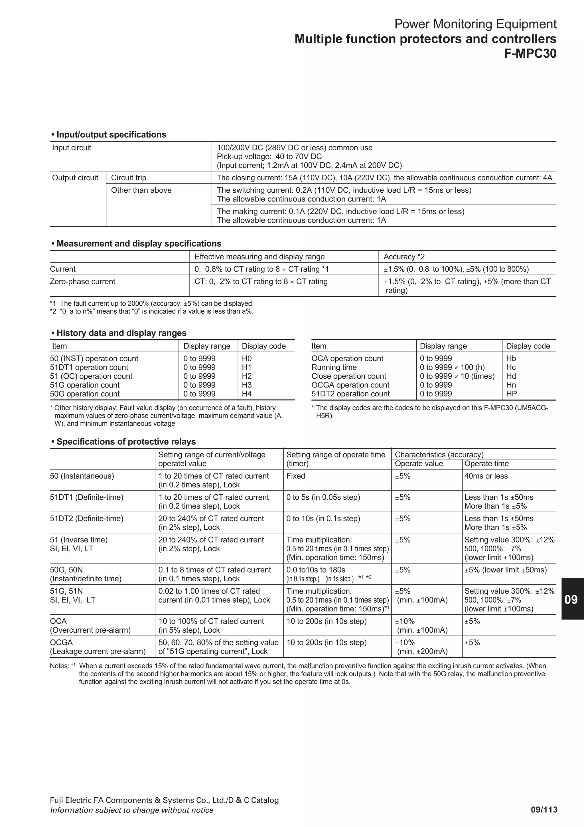
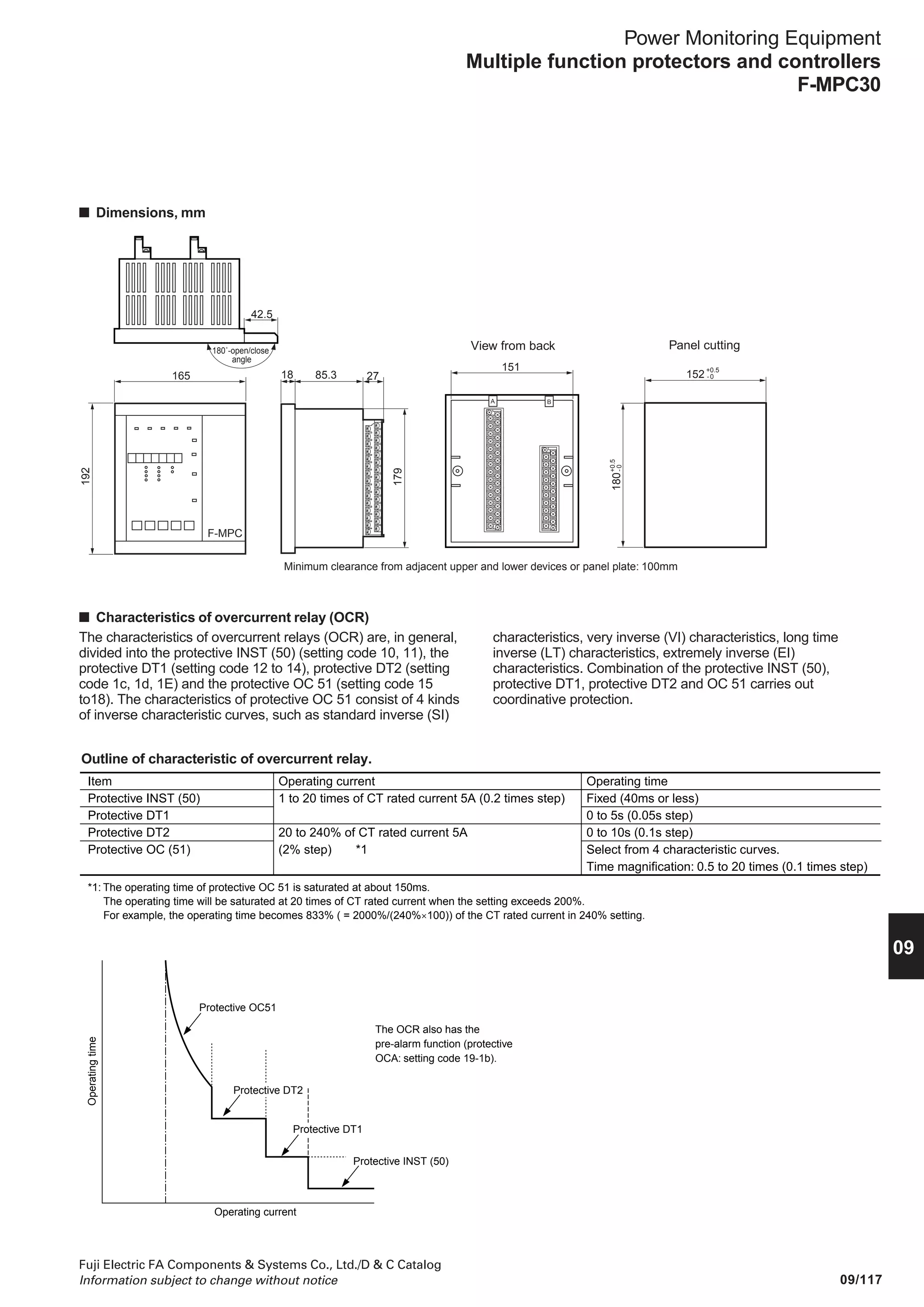
![09/118
Fuji Electric FA Components Systems Co., Ltd./D C Catalog
Information subject to change without notice
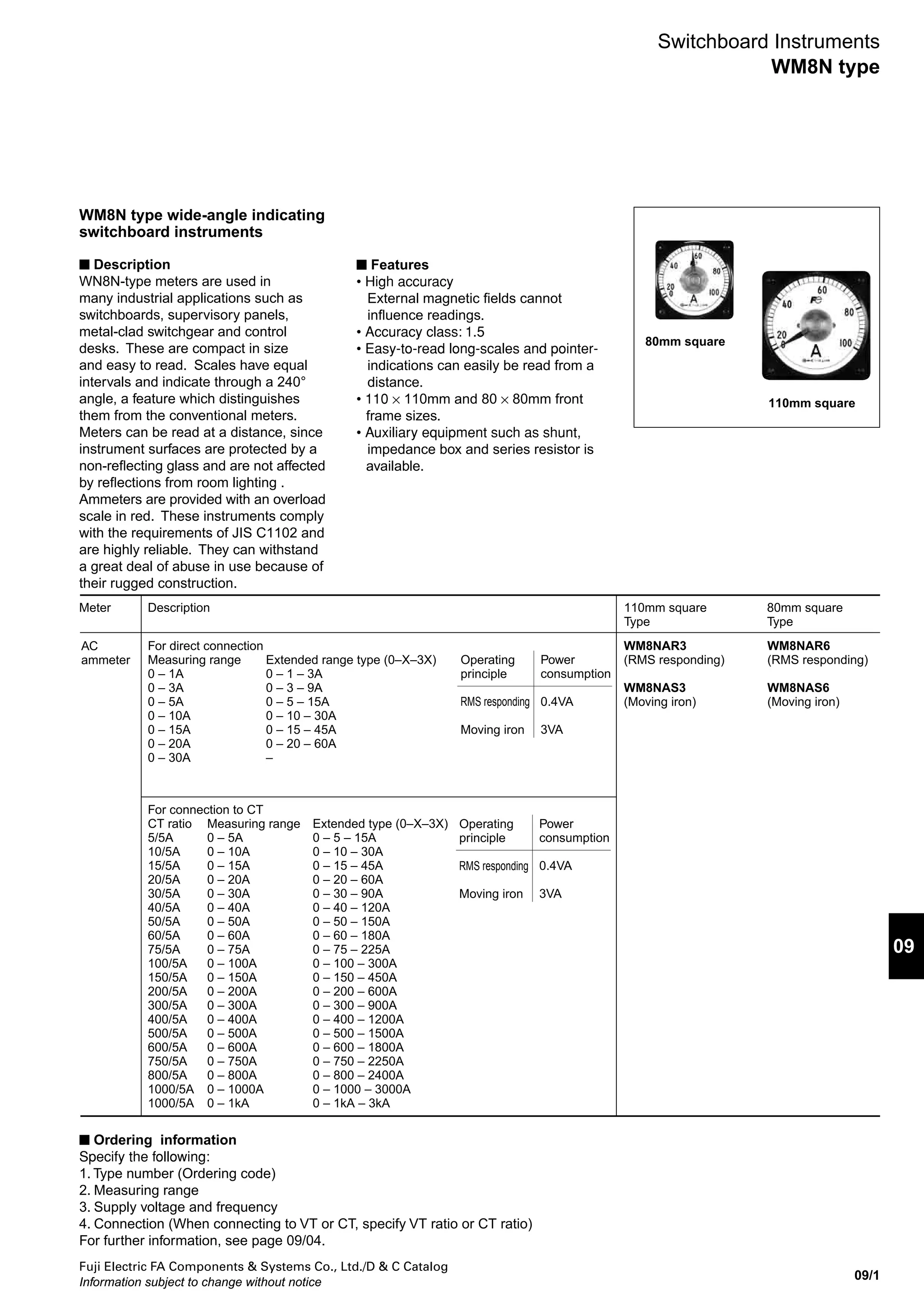
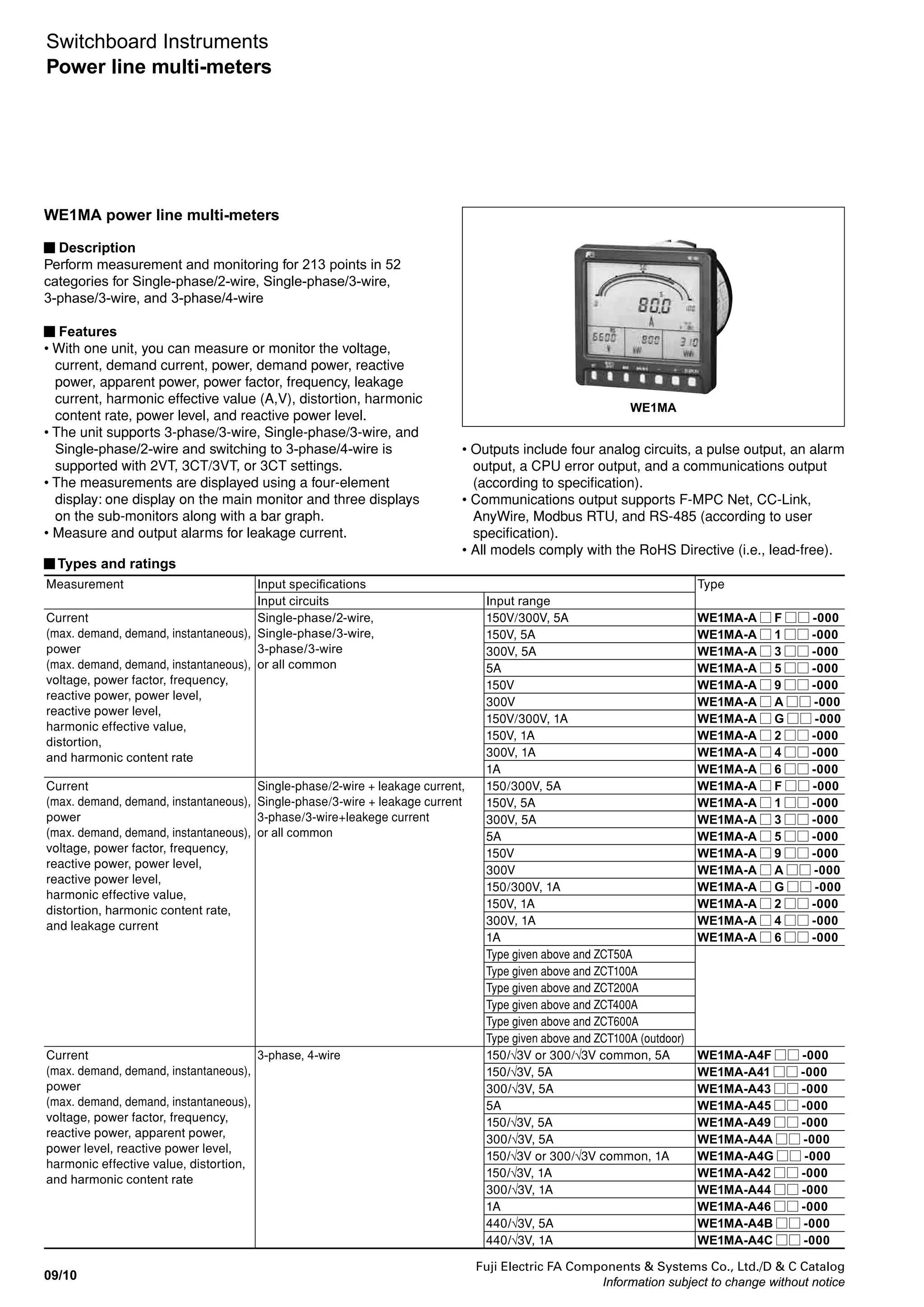
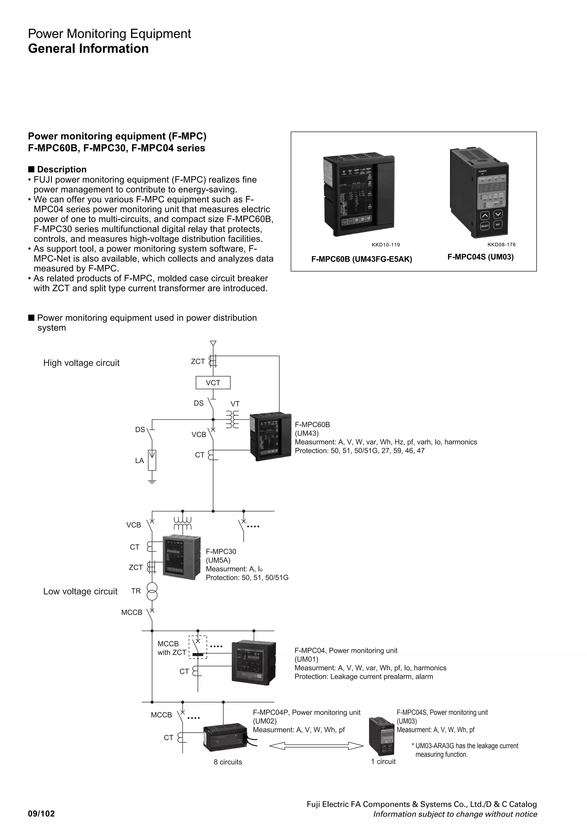
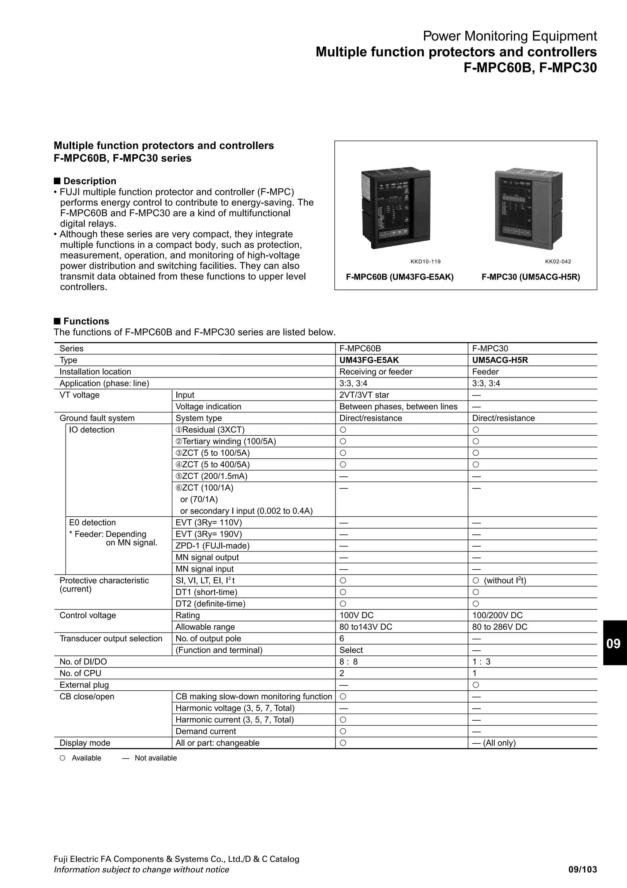
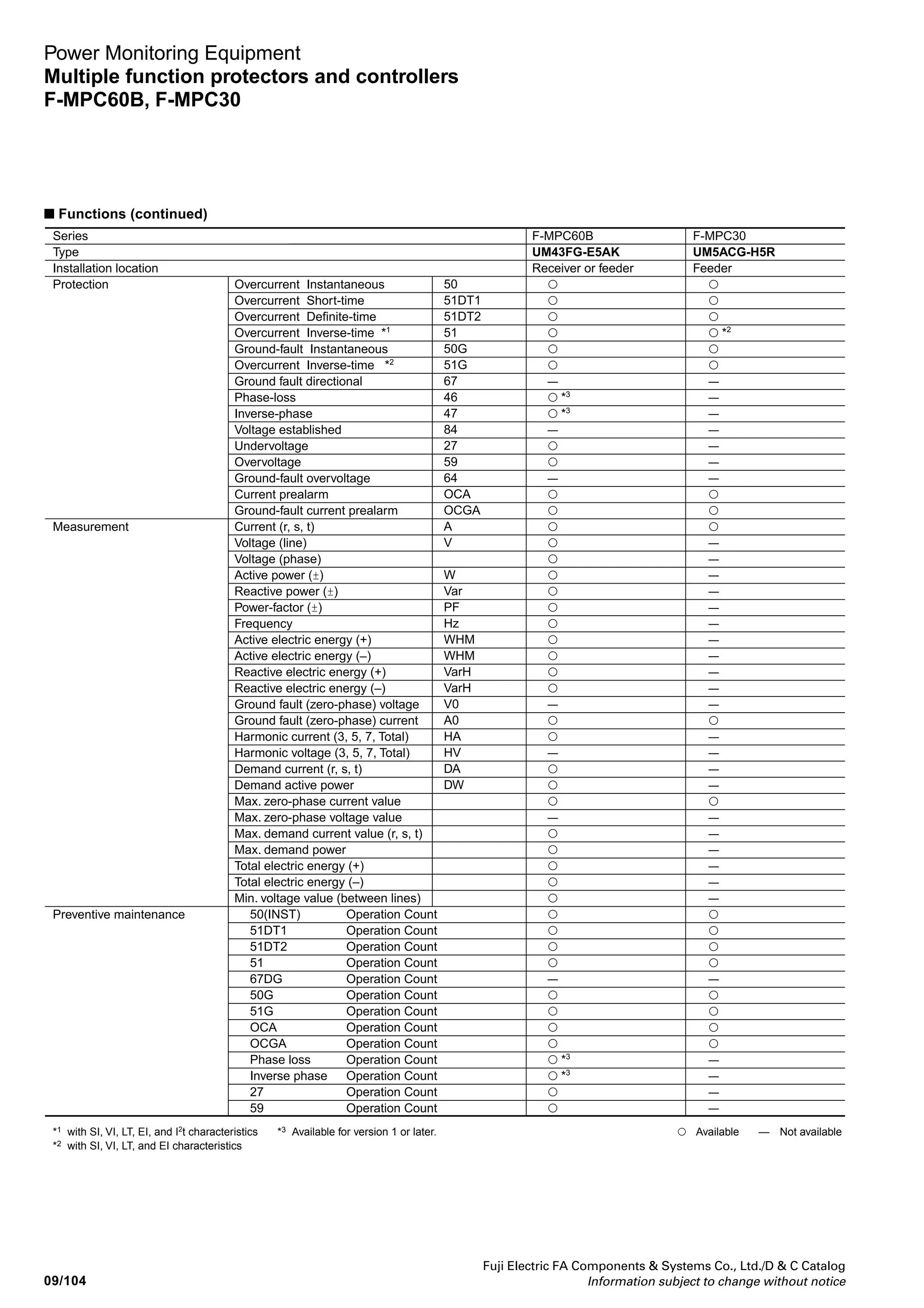
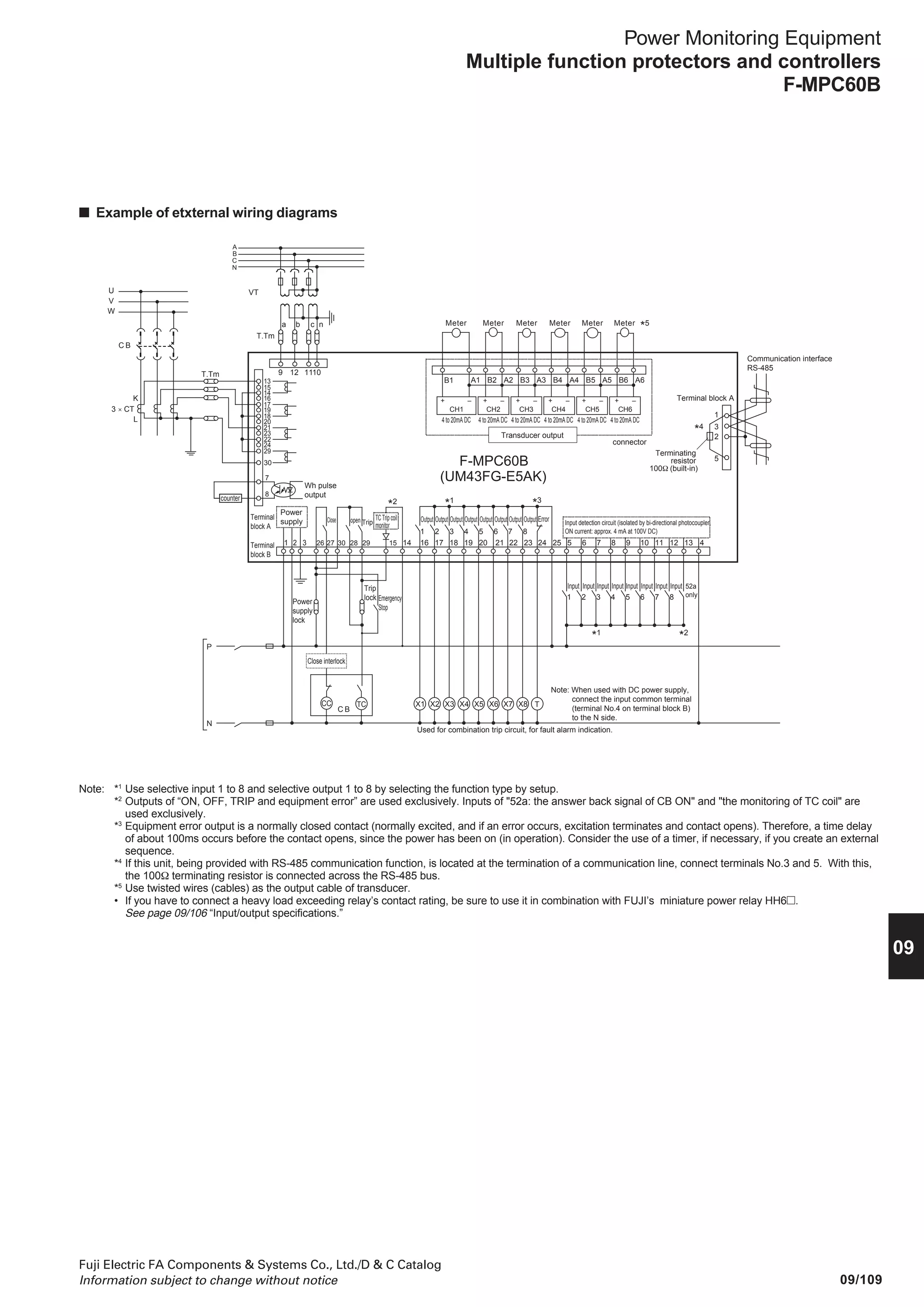
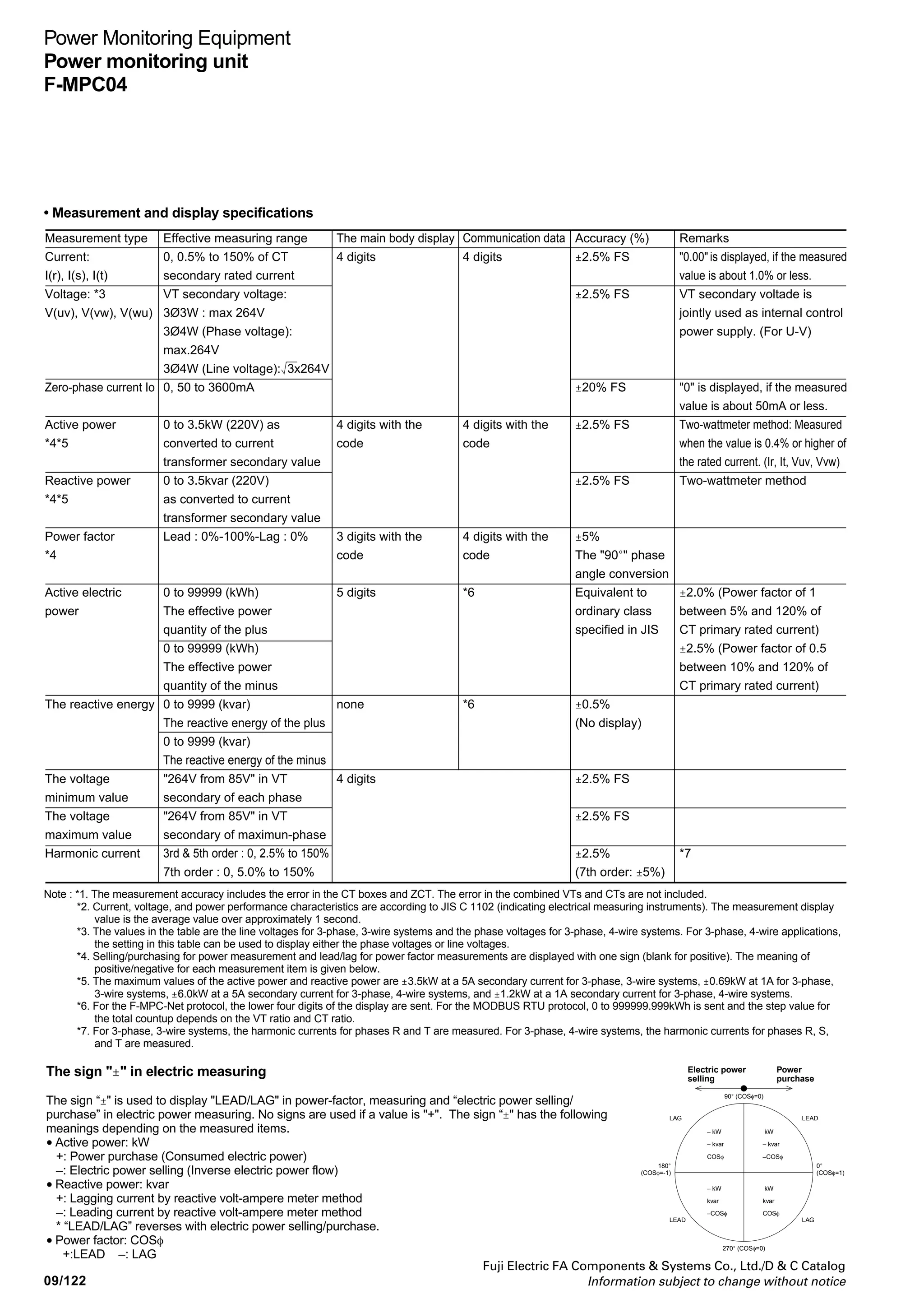
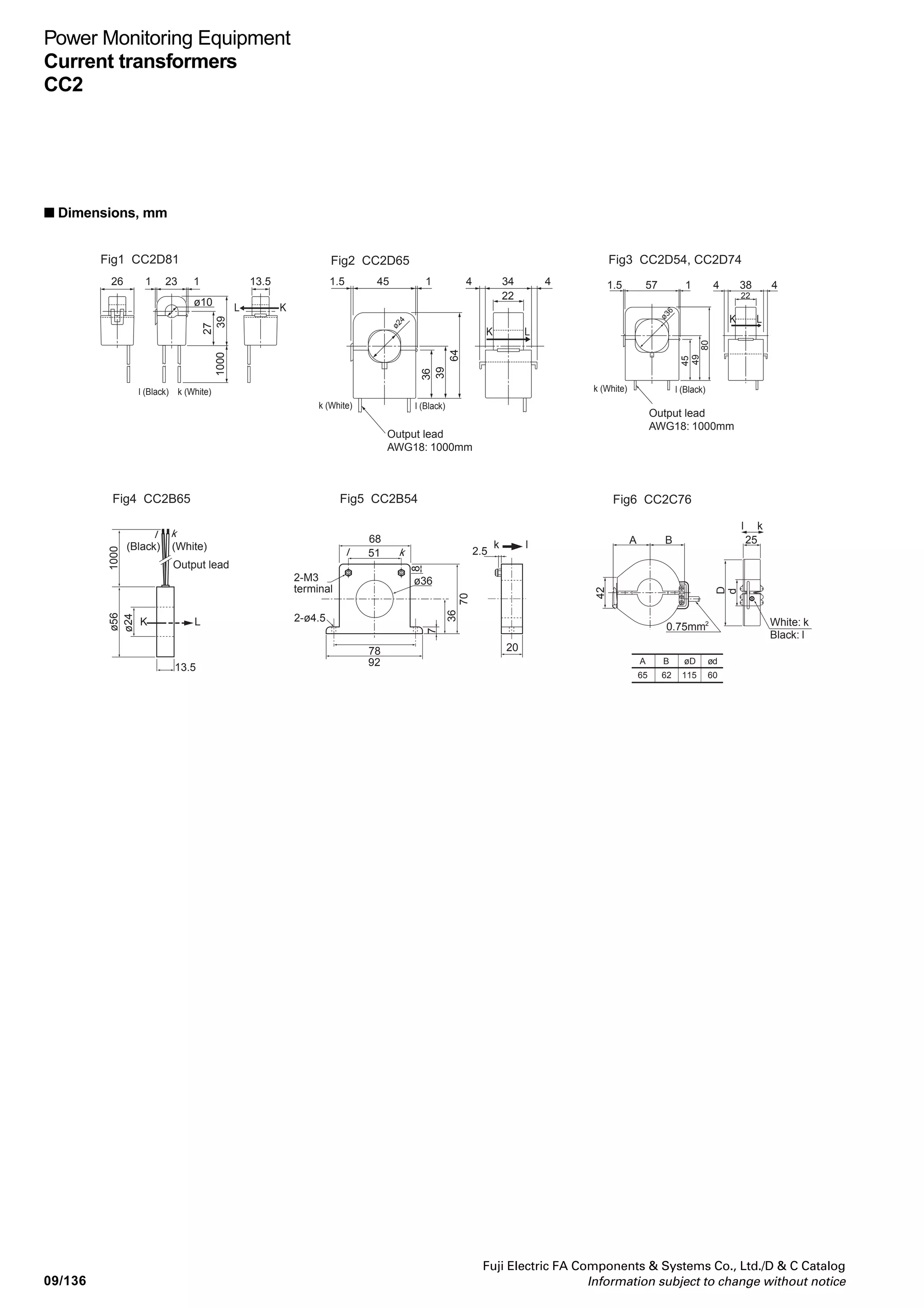
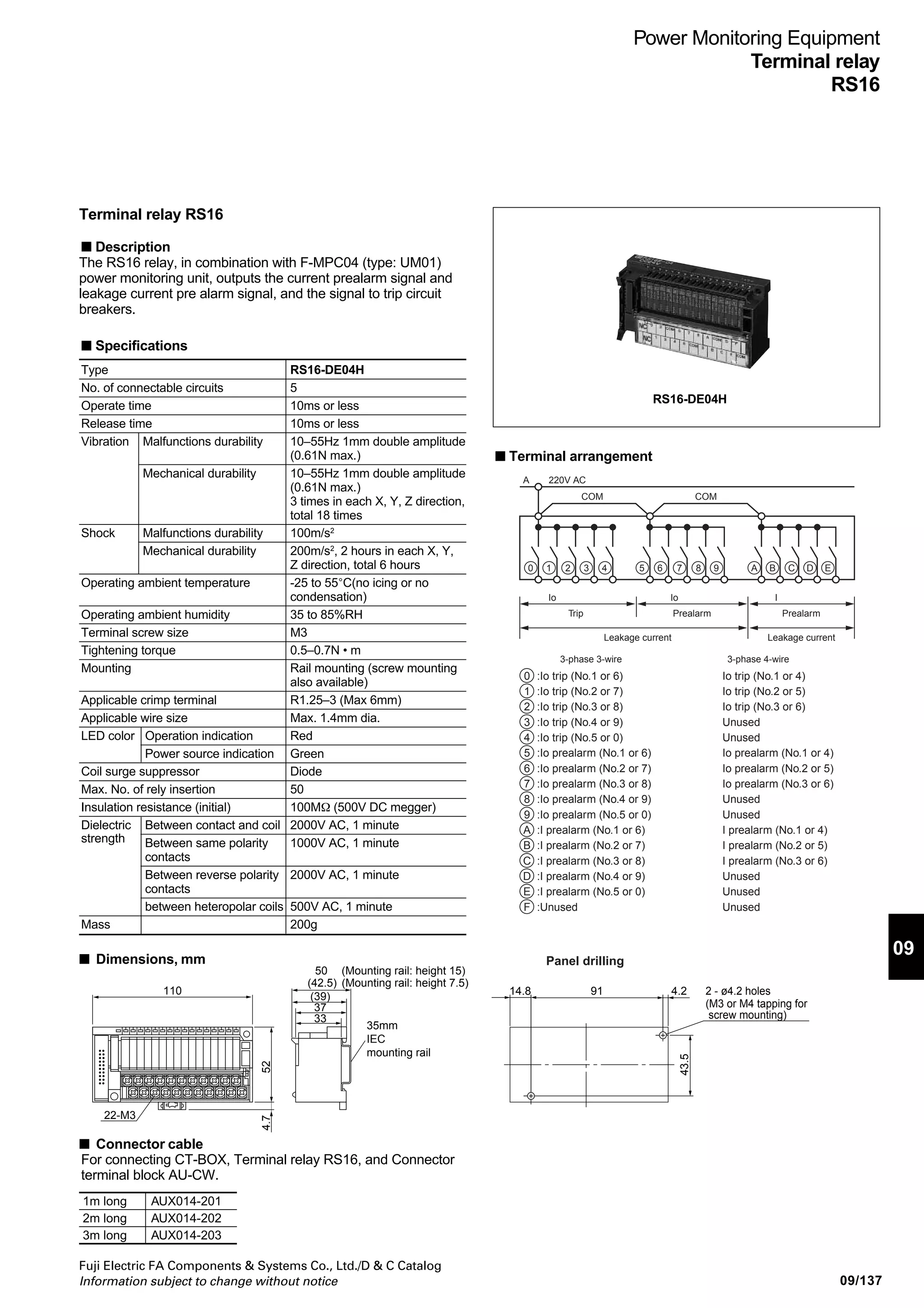
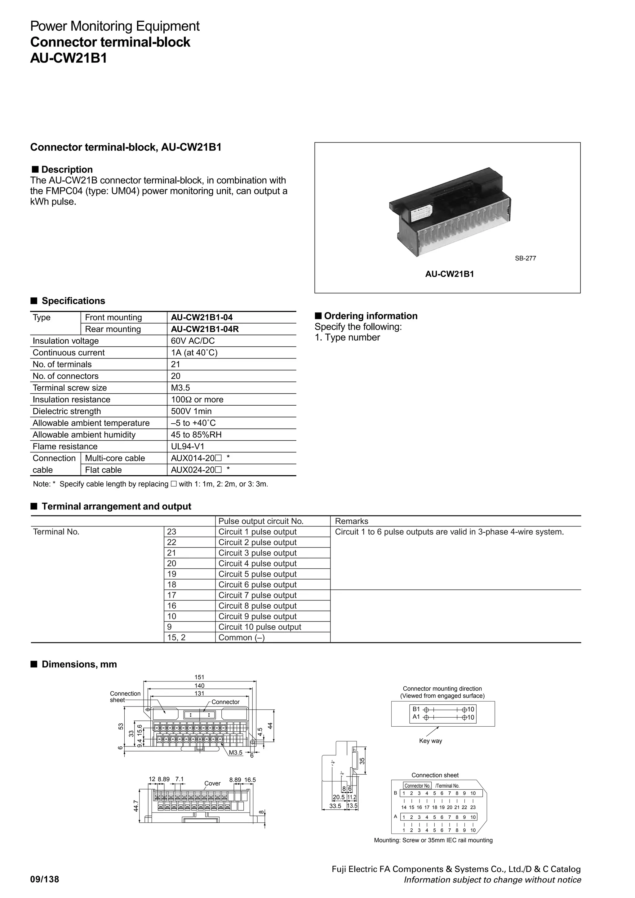
Power Monitoring Equipment
Power monitoring unit
F-MPC04, F-MPC04P, F-MPC04S
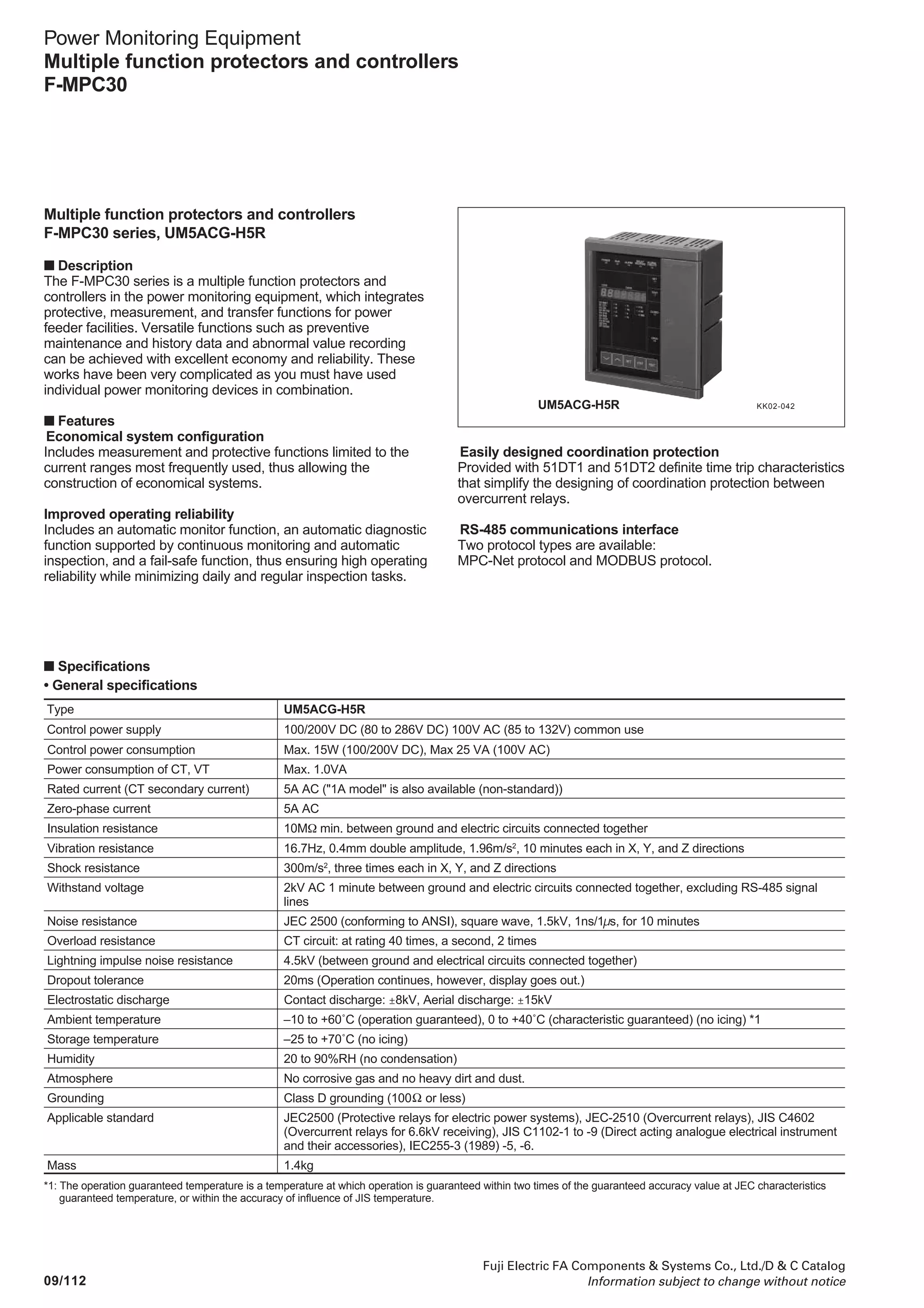
Power monitoring unit F-MPC04 series
■ Description
• F-MPC04 series power monitoring equipment, designed for
used in low voltage circuits, can perform electric power
management and monitoring from high to low voltage circuit
efficiently and economically, used together with F-MPC60B
and F-MPC30 series.
• F-MPC04 series consists of 3 types: type UM04 integrated
power monitoring unit that can monitors up to 10 feeders, type
UM02 multi-circuit power monitoring unit that is space-saving
and can monitor up to 8 feeders in three-phase three-wire
system, and type UM03 single circuit power monitoring unit,
being compact, that has optimum output functions for
preventive maintenance, and is best suited for installation in a
unit of facility, section, and floor.
• RS-485 communications interface is standard. With our
application software of F-MPC-Net power monitoring system,
you can automatically display, print, and save the data
measured by F-MPC 04 on your PC.
F-MPC04P (UM02)F-MPC04 (UM04) F-MPC04S (UM03)
Measuring
function
Protection
Communications interface
Display and setting
Devices to
be
connected
Type
No. of
phase and
wire
No. of voltage circuit
Measuring
item
Maintenance
item
Harmonic current
Current prealarm (OCA)
Leakage current prealarm (OCGA)
Leakage current trip (OCG)
Current sensor (Current Transformer:CT)
1-phase 2-wire
1-phase 3-wire
3-phase 3-wire
3-phase 4-wire
Voltage
Current
Power
Active power
Reactive power
Reactive energy
Power-factor
Leakage current
Basic component of
leakage current
Demand
Max. voltage value
Min. voltage value
[V]
[A]
[W]
[Wh]
[var]
[varh]
[Io]
[Iob]
Current
Power
Max. current
Max. power
10 circuits
10 circuits
6 circuits
2
ć
ć
ć
ć
ć
ć
ć
ć
ć
ć
ć
ć
ć
ć
ć
ć
ć
ć
ć
RS-485, Modbus
ć
ć *1
12 circuits
—
—
1
RS-485
Display and setting unit UM02X-S
CT: 5, 50, 200, 400A
—
8 circuits
—
ć
ć
ć
ć
ć
–
ć
–
–
–
–
–
ć
ć
ć
–
–
–
–
—
—
4 circuits
1 circuit
—
1
ć
ć
ć
ć
ć
ć
ć
ć
ć
ć
ć
ć
ć
–
–
ć (Demand only)
ć
ć
ć
RS-485
ć
1 circuit
—
1
ć
ć
ć
ć
ć
ć
ć
–
–
ć
ć
ć
ć
–
–
ć
–
–
RS-485
ć
ZCT (separately installed)
MCCB with ZCT
ć
ć
–
–
ć
ć
–
–
Note *1
: FMPC 04 (UM04) is connected to CT via CT-BOX. For combination of
F-MPC04 (UM04), CT-BOX and CT, See page 09/120 and 09/135 ;
Applicable CT.
F-MPC04
UM04-ARAE
Integrated
power
monitoring
unit
F-MPC04P
UM02-AR2
Multi-circuit power monitoring unit
UM02-AR3 UM02-AR4
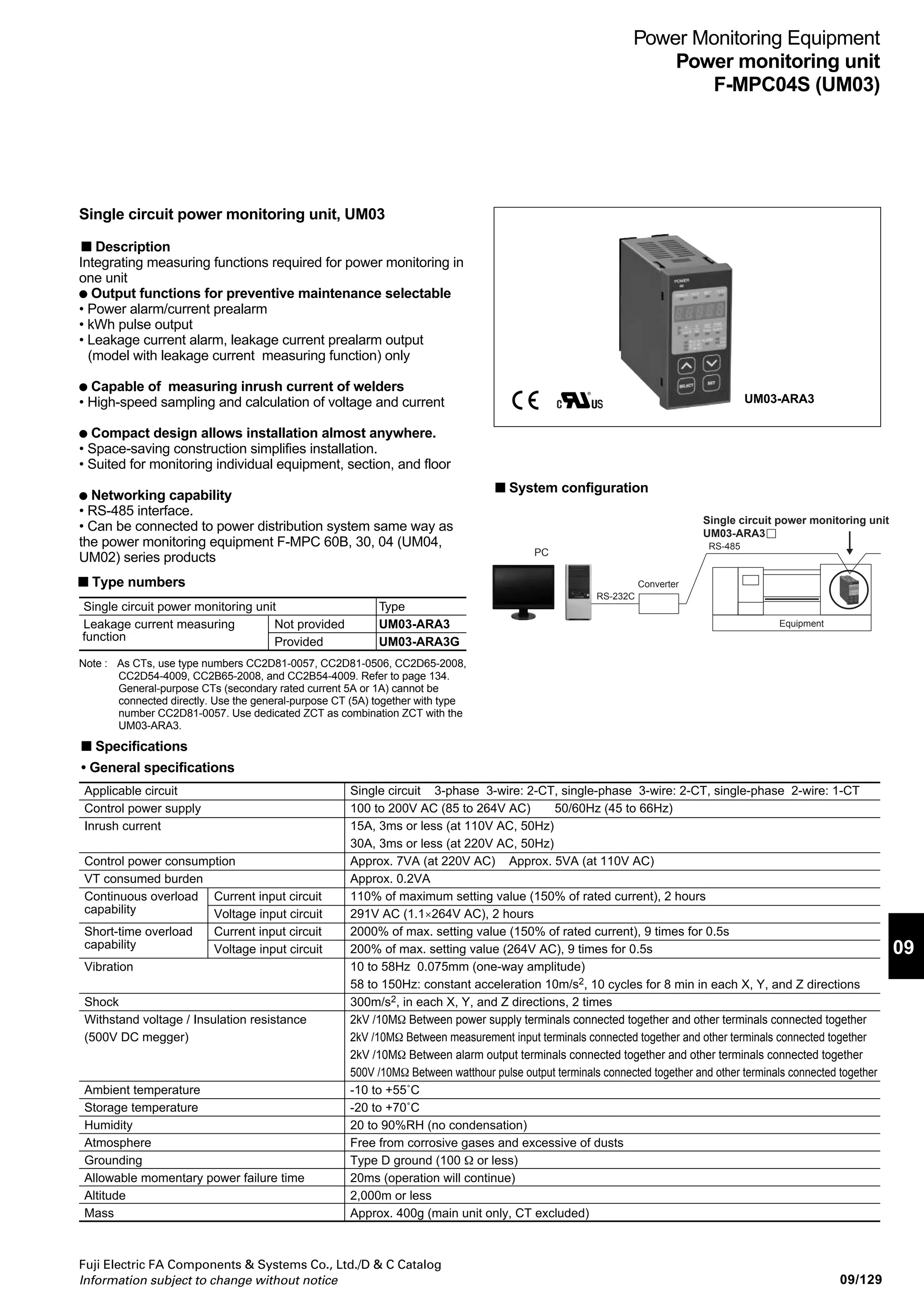
F-MPC04S
UM03-ARA3G
Single-circuit power
monitoring unit
UM03-ARA3](https://image.slidesharecdn.com/dec2009-measuringinstuments-141201203626-conversion-gate01/75/09-Measuring-Instuments-Fuji-Electric-122-2048.jpg)
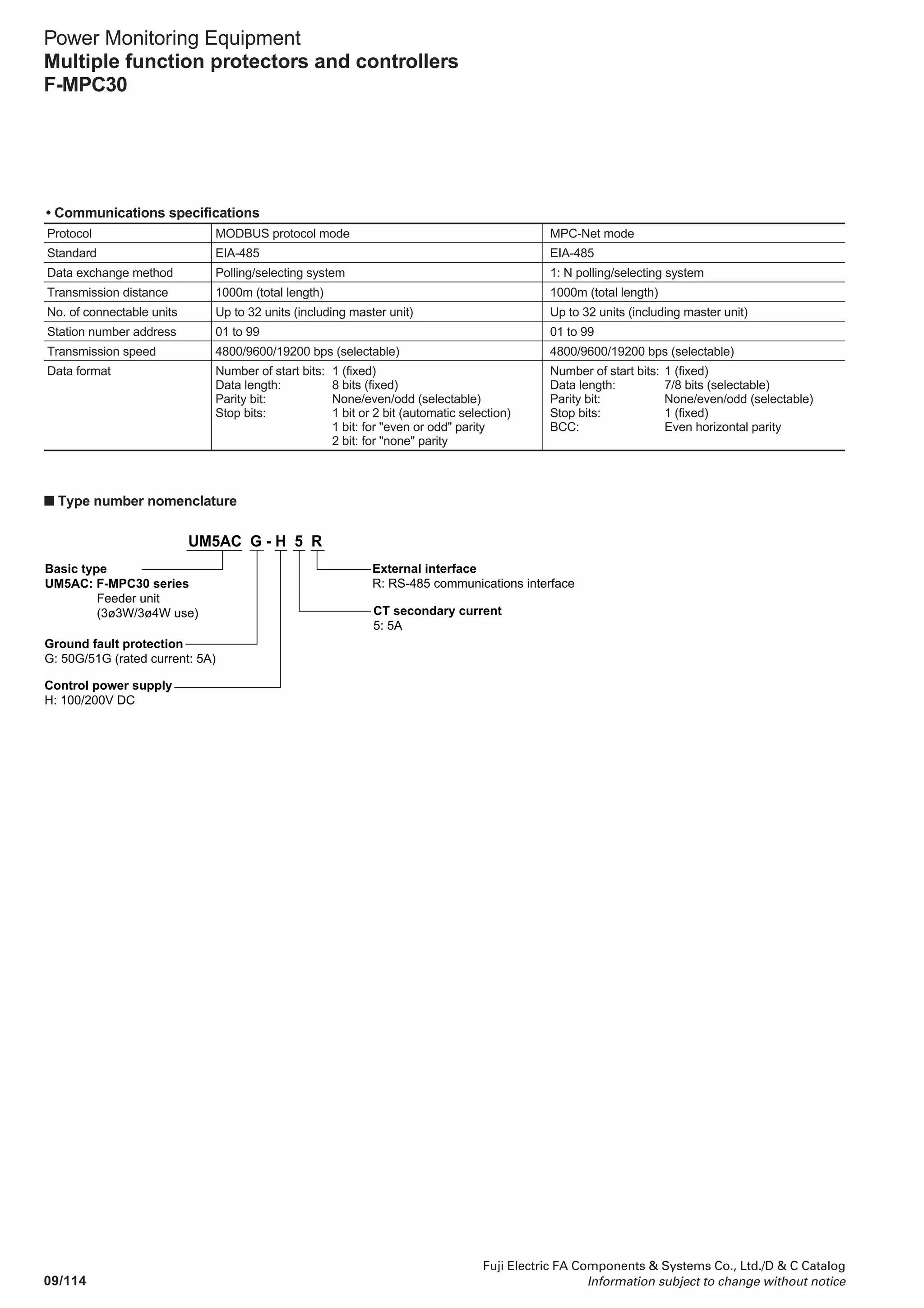
![09/130
Fuji Electric FA Components Systems Co., Ltd./D C Catalog
Information subject to change without notice
Power Monitoring Equipment
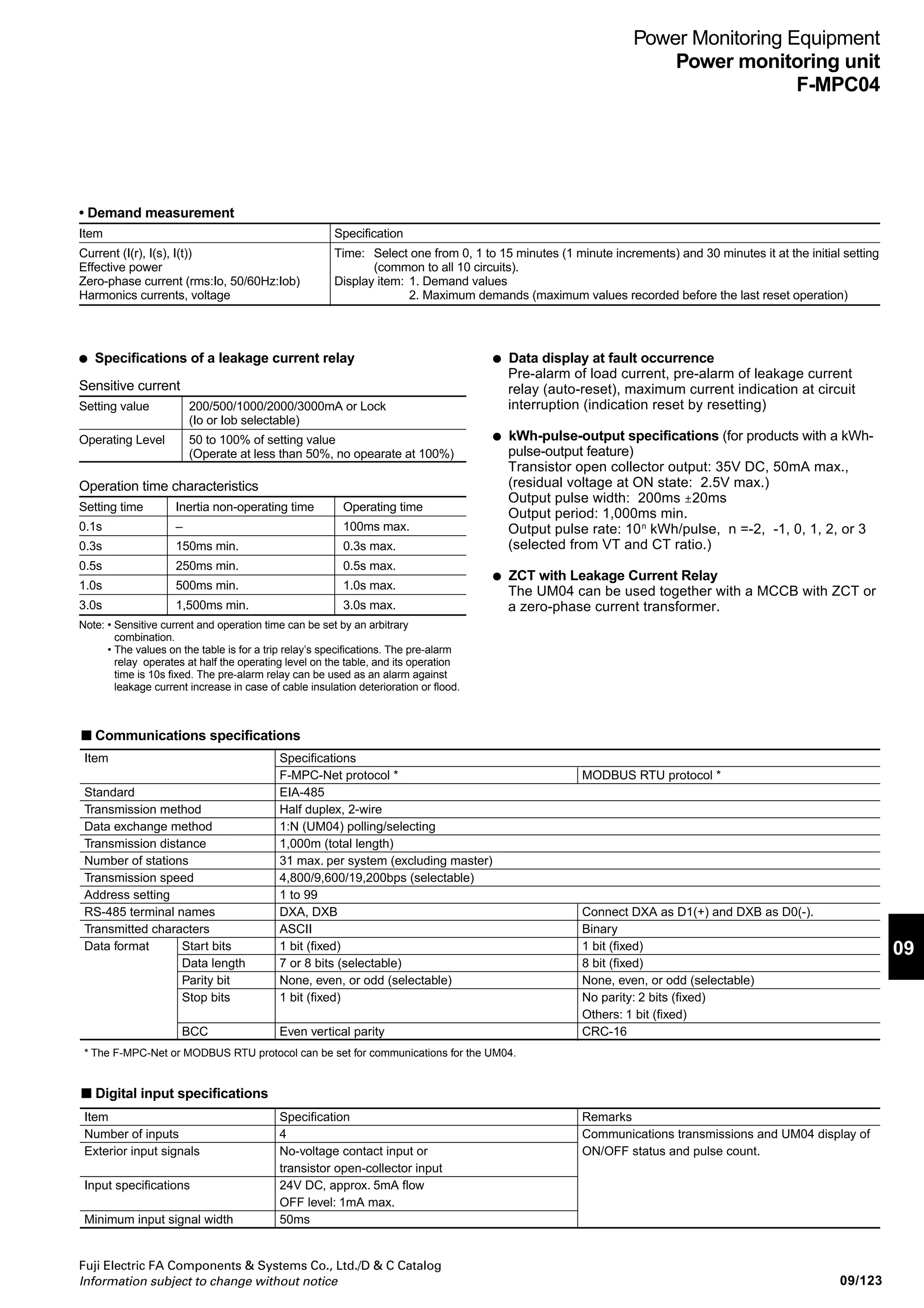
Power monitoring unit
F-MPC04S (UM03)
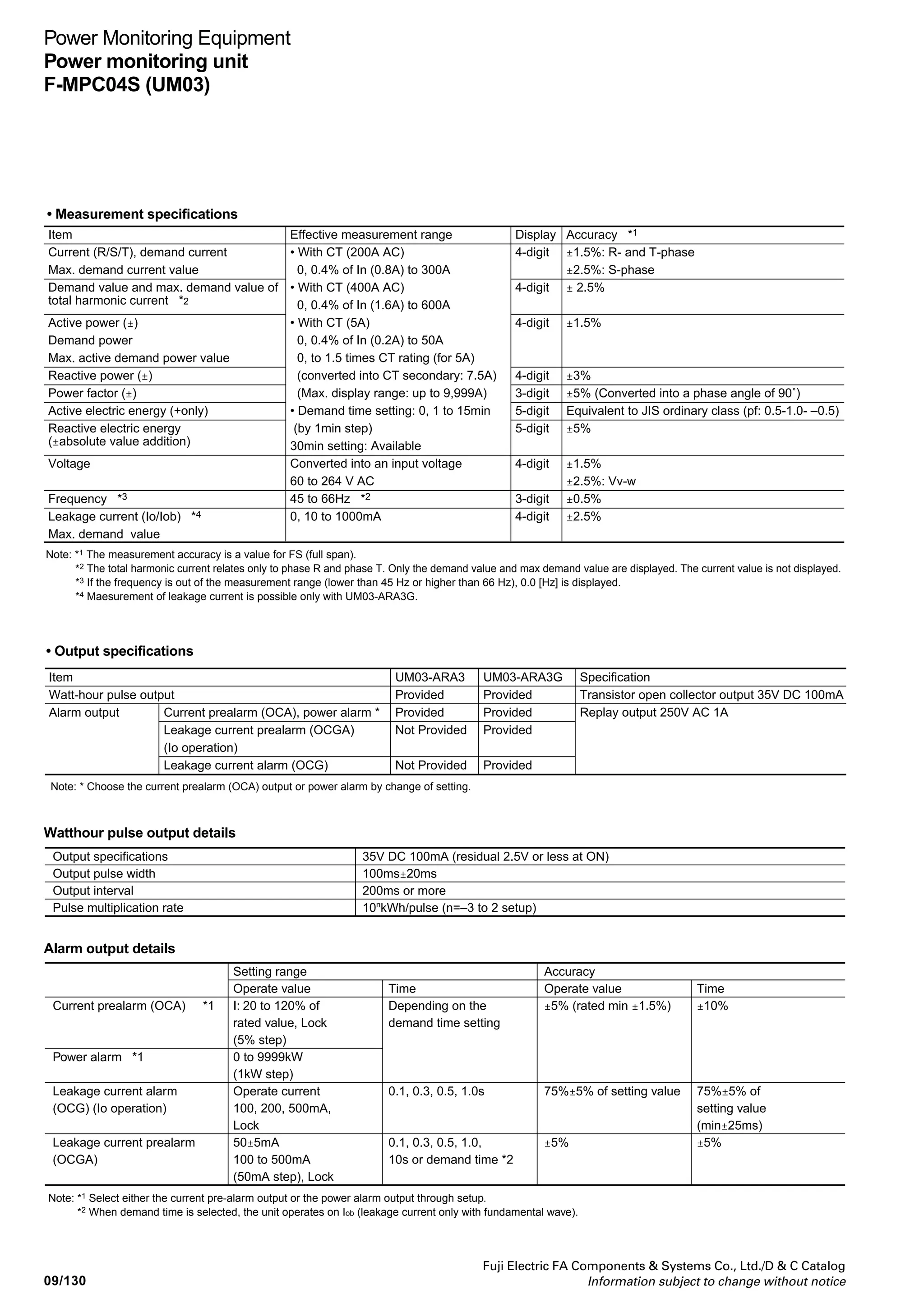
Current prealarm (OCA) *1
Power alarm *1
Leakage current alarm
(OCG) (Io operation)
Leakage current prealarm
(OCGA)
Setting range
Operate value
I: 20 to 120% of
rated value, Lock
(5% step)
0 to 9999kW
(1kW step)
Operate current
100, 200, 500mA,
Lock
50±5mA
100 to 500mA
(50mA step), Lock
Note: *1 Select either the current pre-alarm output or the power alarm output through setup.
*2 When demand time is selected, the unit operates on Iob (leakage current only with fundamental wave).
Time
Depending on the
demand time setting
0.1, 0.3, 0.5, 1.0s
0.1, 0.3, 0.5, 1.0,
10s or demand time *2
Accuracy
Operate value
±5% (rated min ±1.5%)
75%±5% of setting value
±5%
Time
±10%
75%±5% of
setting value
(min±25ms)
±5%
Watthour pulse output details
Alarm output details
Output specifications
Output pulse width
Output interval
Pulse multiplication rate
35V DC 100mA (residual 2.5V or less at ON)
100ms±20ms
200ms or more
10n
kWh/pulse (n=–3 to 2 setup)
Item
Current (R/S/T), demand current
Max. demand current value
Demand value and max. demand value of
total harmonic current *2
Active power (±)
Demand power
Max. active demand power value
Reactive power (±)
Power factor (±)
Active electric energy (+only)
Reactive electric energy
(±absolute value addition)
Voltage
Frequency *3
Leakage current (Io/Iob) *4
Max. demand value
Effective measurement range
• With CT (200A AC)
0, 0.4% of In (0.8A) to 300A
• With CT (400A AC)
0, 0.4% of In (1.6A) to 600A
• With CT (5A)
0, 0.4% of In (0.2A) to 50A
0, to 1.5 times CT rating (for 5A)
(converted into CT secondary: 7.5A)
(Max. display range: up to 9,999A)
• Demand time setting: 0, 1 to 15min
(by 1min step)
30min setting: Available
Converted into an input voltage
60 to 264 V AC
45 to 66Hz *2
0, 10 to 1000mA
Accuracy *1
±1.5%: R- and T-phase
±2.5%: S-phase
± 2.5%
±1.5%
±3%
±5% (Converted into a phase angle of 90˚)
Equivalent to JIS ordinary class (pf: 0.5-1.0- –0.5)
±5%
±1.5%
±2.5%: Vv-w
±0.5%
±2.5%
Display
4-digit
4-digit
4-digit
4-digit
3-digit
5-digit
5-digit
4-digit
3-digit
4-digit
Note: *1 The measurement accuracy is a value for FS (full span).
*2 The total harmonic current relates only to phase R and phase T. Only the demand value and max demand value are displayed. The current value is not displayed.
*3 If the frequency is out of the measurement range (lower than 45 Hz or higher than 66 Hz), 0.0 [Hz] is displayed.
*4 Maesurement of leakage current is possible only with UM03-ARA3G.
• Measurement specifications
• Output specifications
Item
Watt-hour pulse output
Alarm output
Note: * Choose the current prealarm (OCA) output or power alarm by change of setting.
Current prealarm (OCA), power alarm *
Leakage current prealarm (OCGA)
(Io operation)
Leakage current alarm (OCG)
UM03-ARA3
Provided
Provided
Not Provided
Not Provided
UM03-ARA3G
Provided
Provided
Provided
Provided
Specification
Transistor open collector output 35V DC 100mA
Replay output 250V AC 1A](https://image.slidesharecdn.com/dec2009-measuringinstuments-141201203626-conversion-gate01/75/09-Measuring-Instuments-Fuji-Electric-134-2048.jpg)
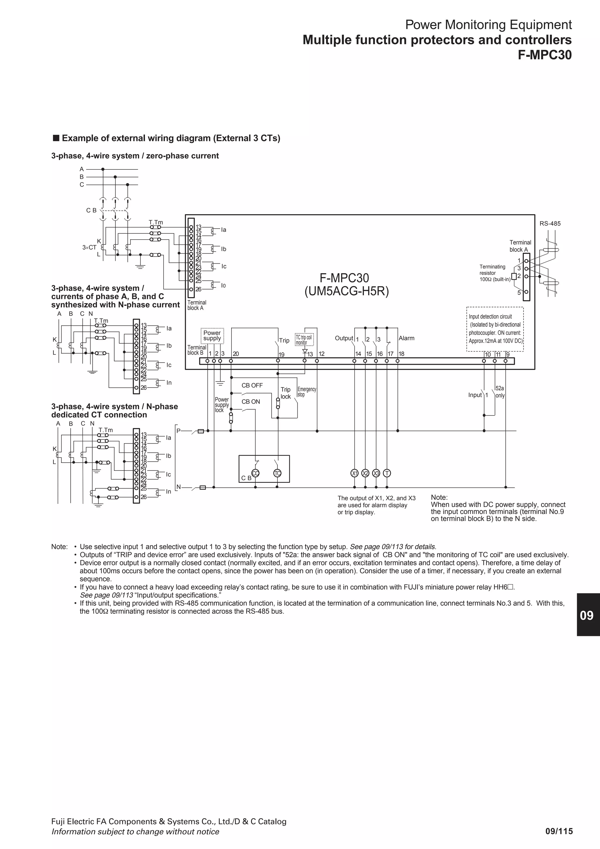
![09/132
Fuji Electric FA Components Systems Co., Ltd./D C Catalog
Information subject to change without notice
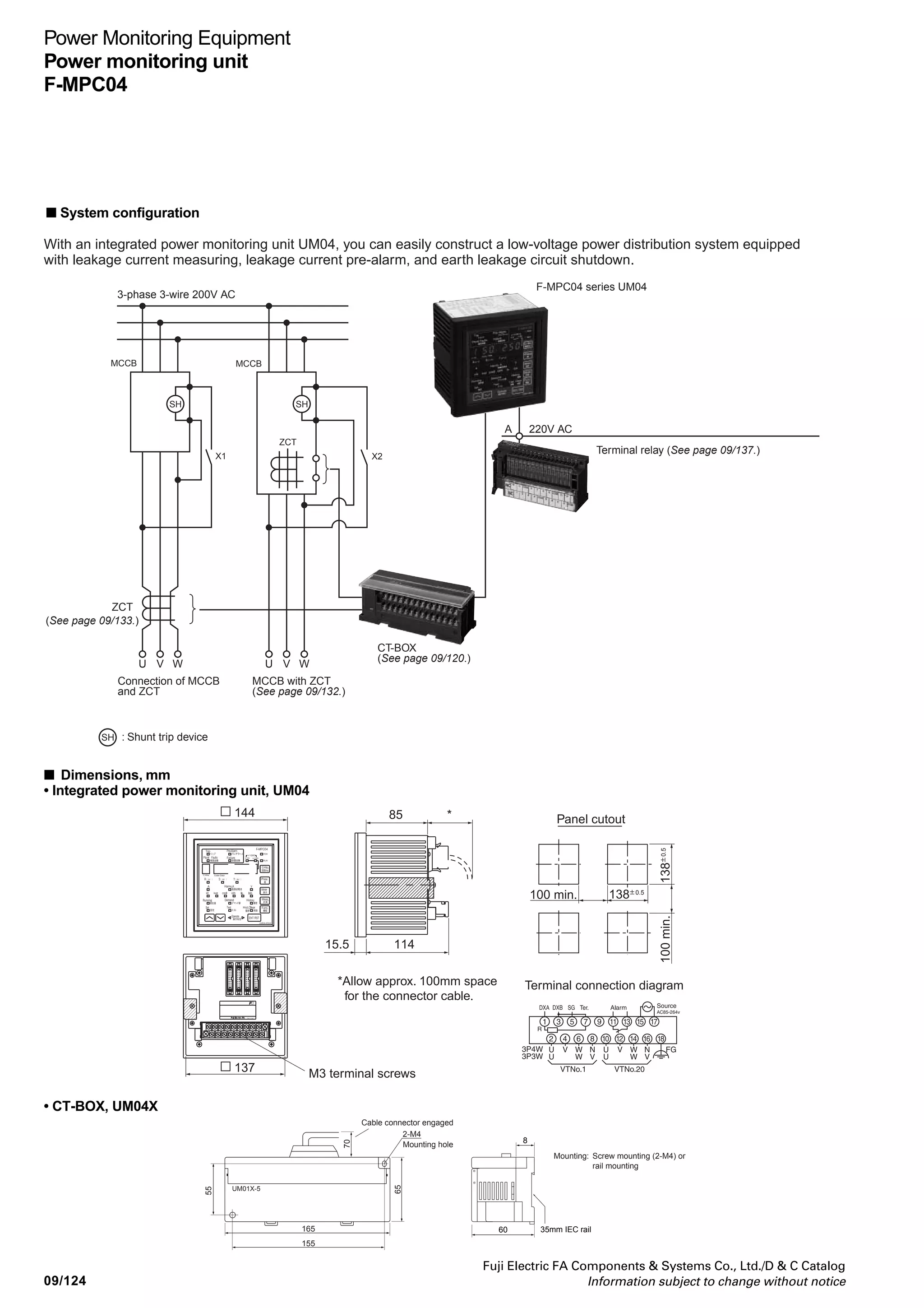
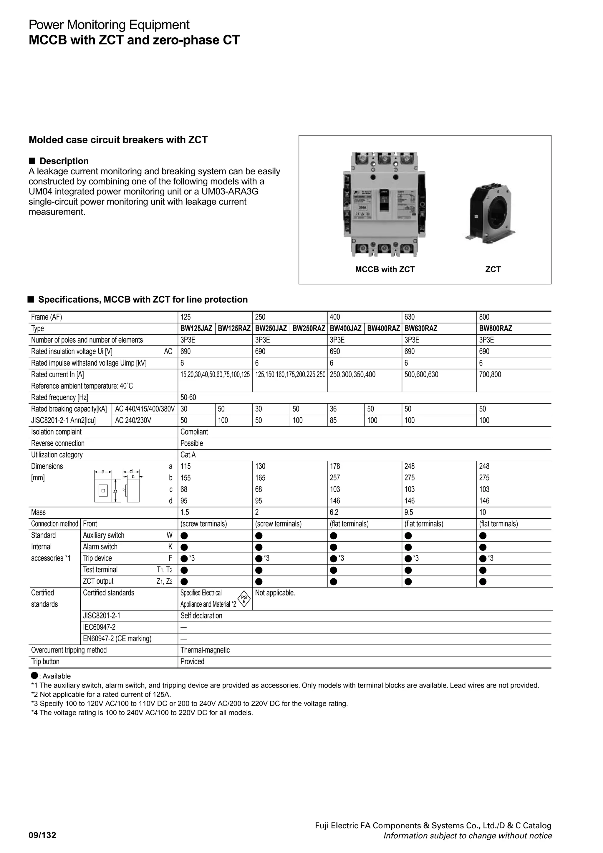
Power Monitoring Equipment
MCCB with ZCT and zero-phase CT
MCCB with ZCT ZCT
Molded case circuit breakers with ZCT
■ Description
A leakage current monitoring and breaking system can be easily
constructed by combining one of the following models with a
UM04 integrated power monitoring unit or a UM03-ARA3G
single-circuit power monitoring unit with leakage current
measurement.
■ Specifications, MCCB with ZCT for line protection
Frame (AF)
Type
Number of poles and number of elements
Rated insulation voltage Ui [V]
Rated impulse withstand voltage Uimp [kV]
Rated current In [A]
Reference ambient temperature: 40˚C
Rated frequency [Hz]
Rated breaking capacity[kA]
JISC8201-2-1 Ann2[lcu]
Isolation complaint
Reverse connection
Utilization category
Dimensions
[mm]
Mass
Connection method
Standard
Internal
accessories *1
Certified
standards
Overcurrent tripping method
Trip button
: Available
*1 The auxiliary switch, alarm switch, and tripping device are provided as accessories. Only models with terminal blocks are available. Lead wires are not provided.
*2 Not applicable for a rated current of 125A.
*3 Specify 100 to 120V AC/100 to 110V DC or 200 to 240V AC/200 to 220V DC for the voltage rating.
*4 The voltage rating is 100 to 240V AC/100 to 220V DC for all models.
AC 440/415/400/380V
AC 240/230V
Front
Auxiliary switch
Alarm switch
Trip device
Test terminal
ZCT output
Certified standards
JISC8201-2-1
IEC60947-2
EN60947-2 (CE marking)
AC
a
b
c
d
W
K
F
T1, T2
Z1, Z2
125
BW125JAZ
3P3E
690
6
15,20,30,40,50,60,75,100,125
50-60
30
50
Compliant
Possible
Cat.A
115
155
68
95
1.5
(screw terminals)
*3
Specified Electrical
Appliance and Material *2
Self declaration
—
—
Thermal-magnetic
Provided
250
BW250JAZ
3P3E
690
6
125,150,160,175,200,225,250
30
50
130
165
68
95
2
(screw terminals)
*3
Not applicable.
400
BW400JAZ
3P3E
690
6
250,300,350,400
36
85
178
257
103
146
6.2
(flat terminals)
*3
630
BW630RAZ
3P3E
690
6
500,600,630
50
100
248
275
103
146
9.5
(flat terminals)
*3
800
BW800RAZ
3P3E
690
6
700,800
50
100
248
275
103
146
10
(flat terminals)
*3
BW125RAZ
50
100
BW250RAZ
50
100
BW400RAZ
50
100
c
a d
b](https://image.slidesharecdn.com/dec2009-measuringinstuments-141201203626-conversion-gate01/75/09-Measuring-Instuments-Fuji-Electric-136-2048.jpg)


This document is a comprehensive catalog of Fuji Electric's low and high voltage products, including various measuring instruments, relays, circuit breakers, and control equipment, as well as their specifications. It contains contact information for Fuji Electric's offices in Japan, Vietnam, and Cambodia, along with ordering information and weight/dimensional details. Additionally, it mentions that the catalog information is subject to change, emphasizing the importance of confirming details before actual use.


