This document covers transaction management and concurrency control in database principles, outlining the nature of transactions, their properties (atomicity, consistency, isolation, durability, and serializability), and the management techniques associated with SQL. It explains how concurrency control ensures database integrity through locking and scheduling methods, while also detailing database recovery management. Additionally, it highlights the importance of transaction logs and various concurrency control mechanisms, including optimistic methods and deadlock handling strategies.
![*
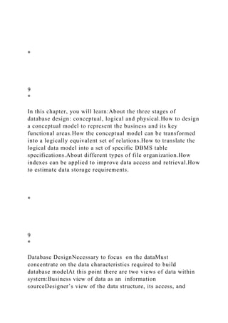
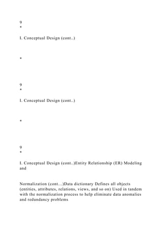
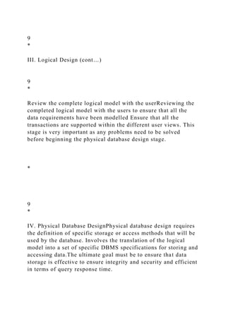
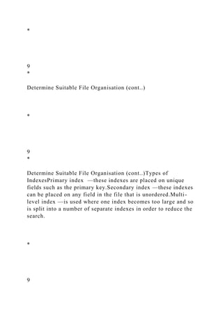
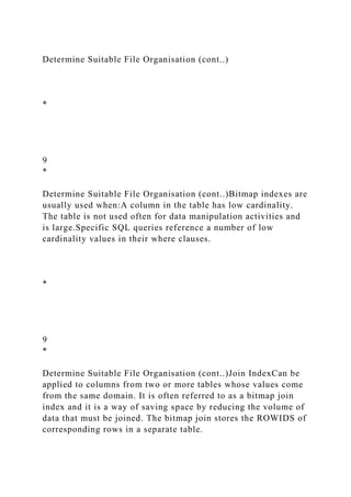
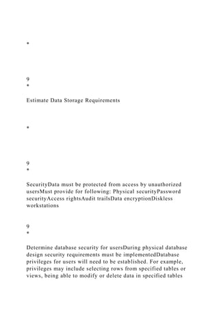
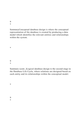
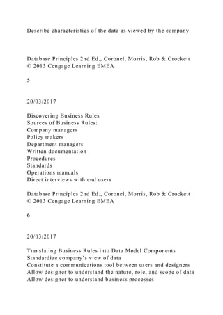
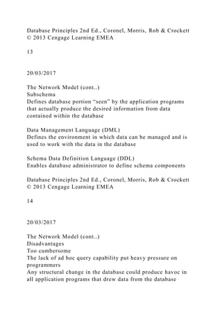
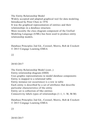
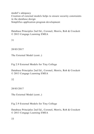
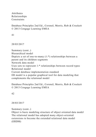
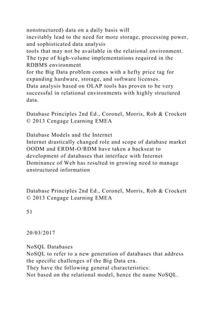
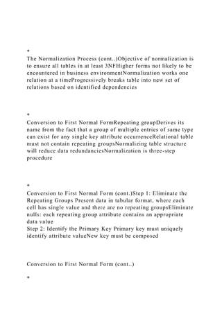
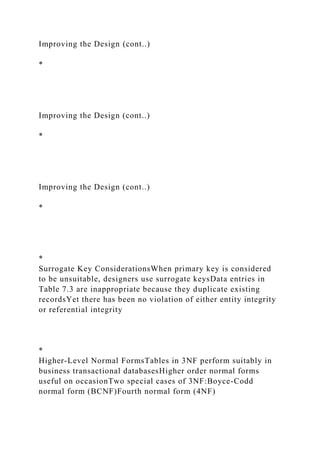
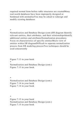
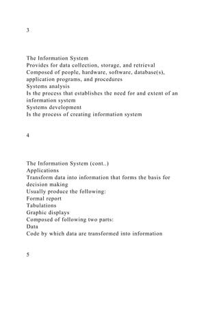
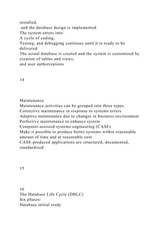
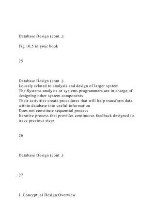
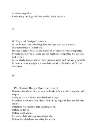
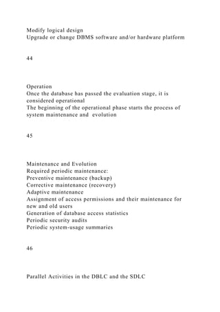
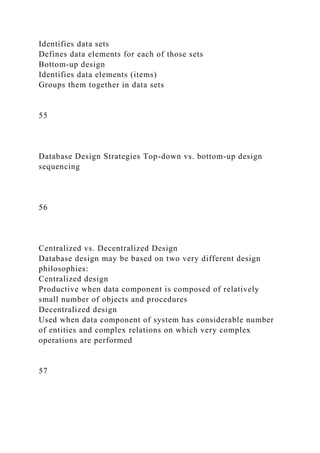
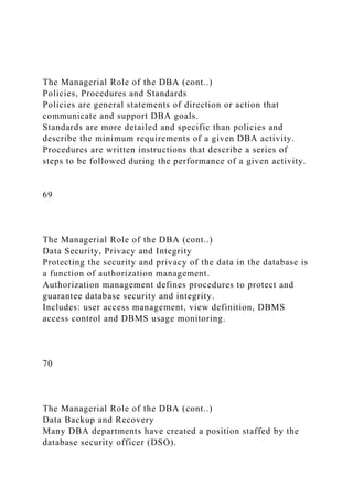
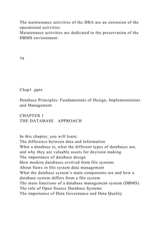
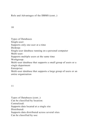
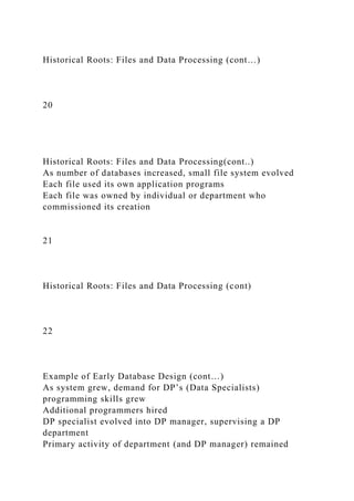
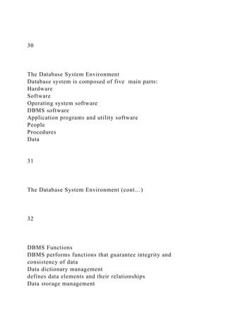
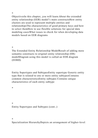
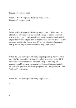
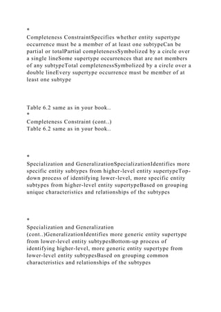
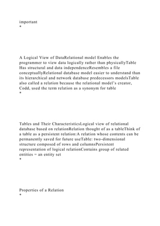
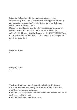
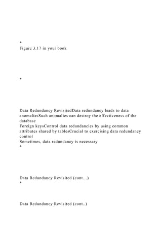
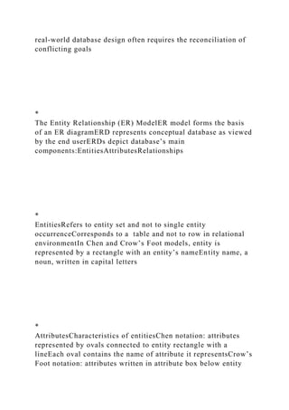
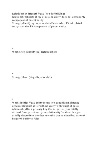
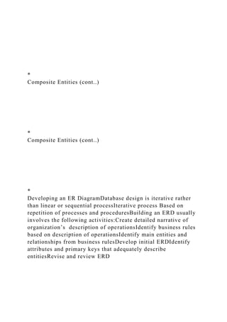
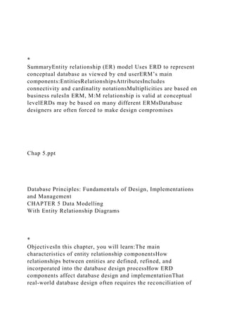
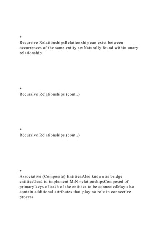
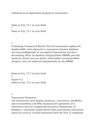
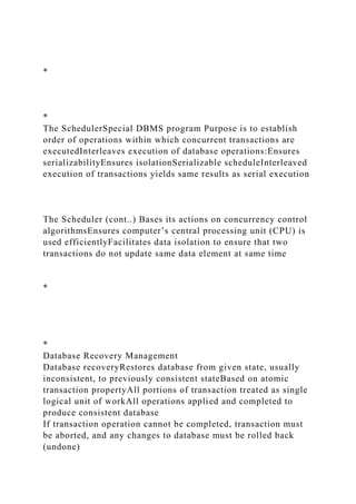
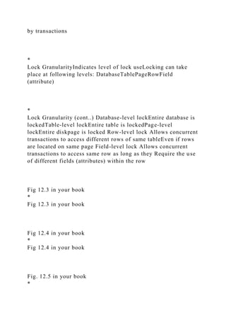
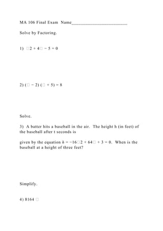
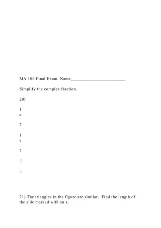
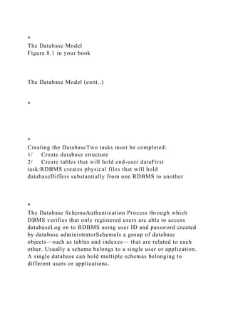
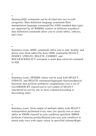
Saving Table ChangesChanges made to table contents are not
physically saved on disk until:Database is closedProgram is
closedCOMMIT command is usedSyntax:COMMIT
[WORK];Will permanently save any changes made to any table
in the database
*
Listing Table RowsSELECT Used to list contents of
tableSyntax: SELECT columnlistFROM tablename;Columnlist
represents one or more attributes, separated by commasAsterisk
can be used as wildcard character to list all attributes
Listing Table Rows (cont..)
*
*
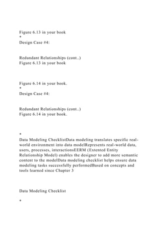
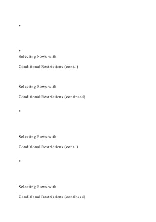
Updating Table RowsUPDATE Modify data in a tableSyntax:
UPDATE tablename
SET columnname = expression [, columnname = expression]
[WHERE conditionlist];If more than one attribute is to be
updated in row, separate corrections with commas](https://image.slidesharecdn.com/dbf-lecture11-chapter12-221226172622-96468150/85/DBF-Lecture11-Chapter12-pptDatabase-Principles-Fundam-docx-30-320.jpg)
![*
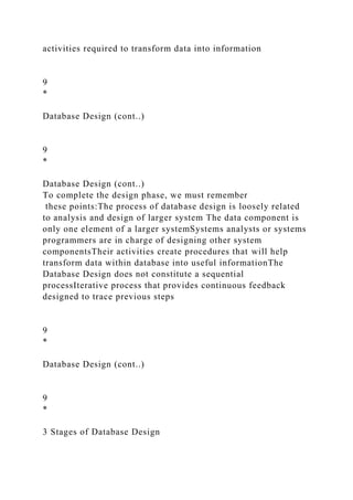
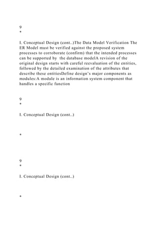
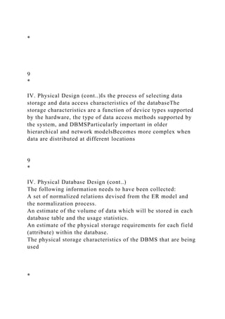
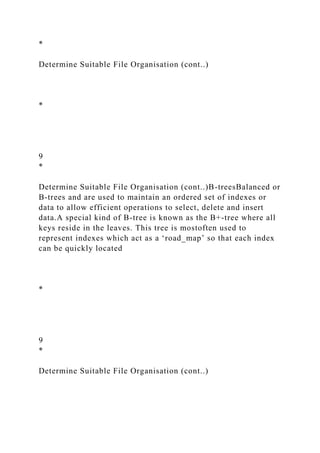
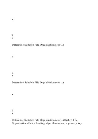
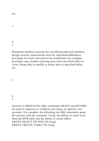
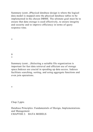
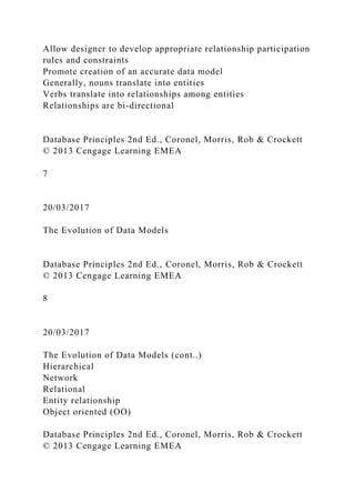
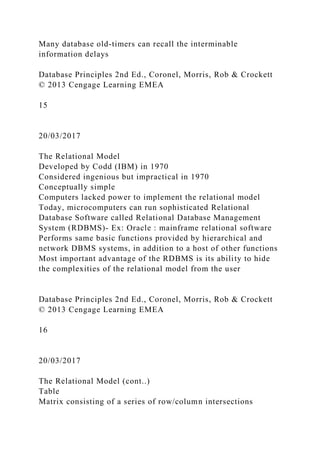
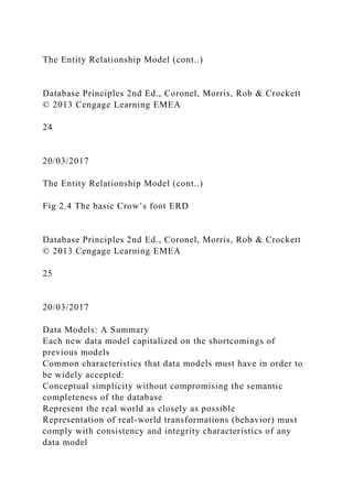
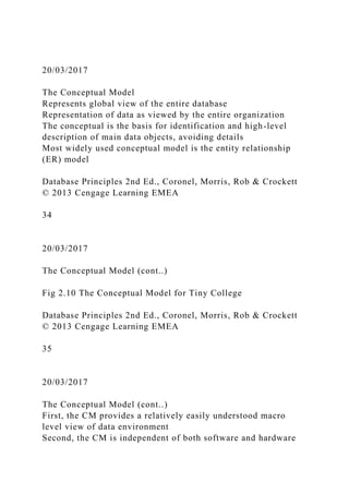
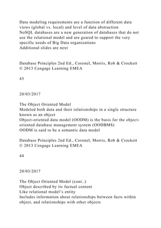
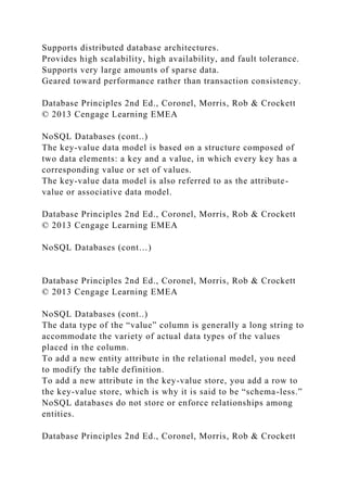
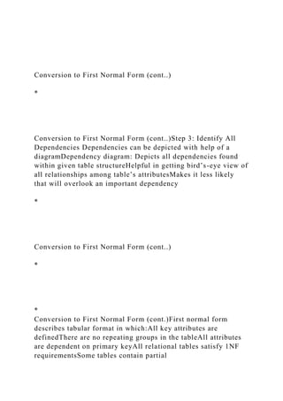
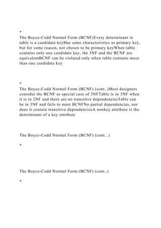
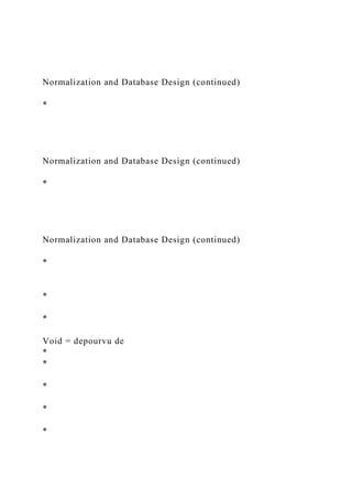
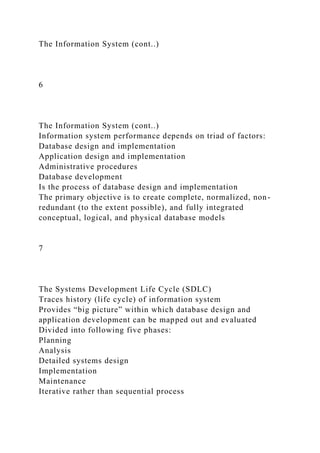
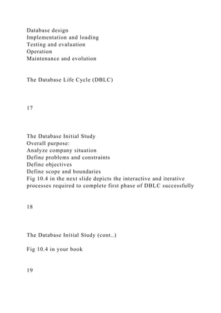
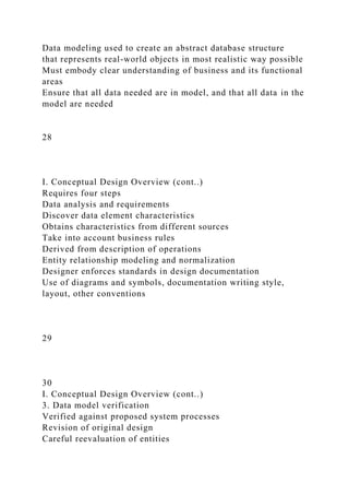
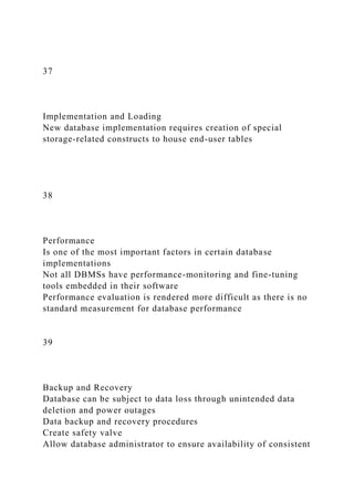
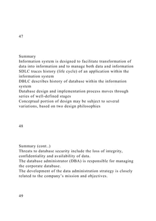
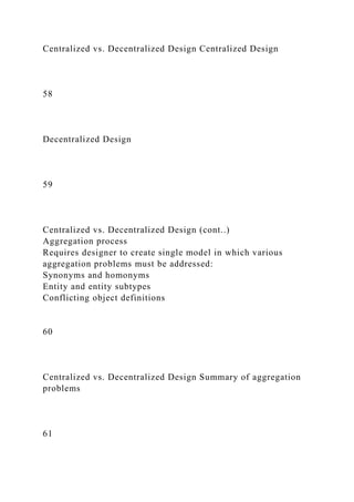
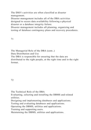
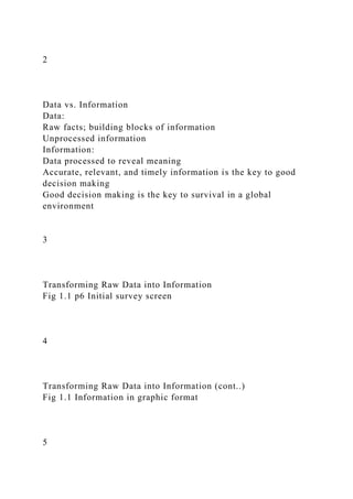
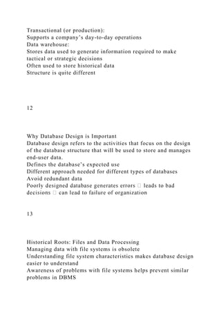
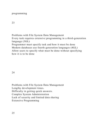
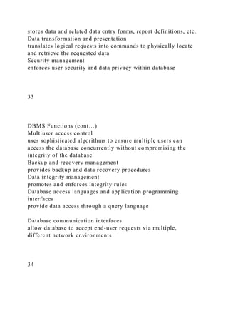
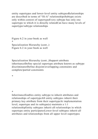
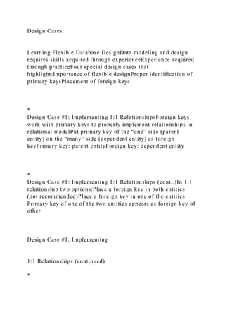
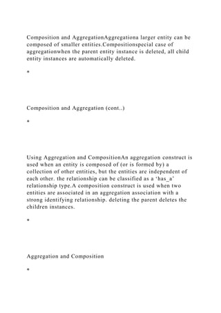
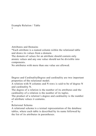
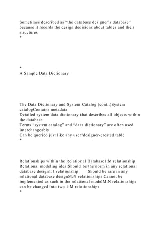
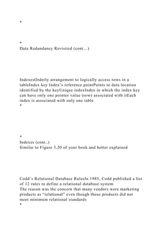
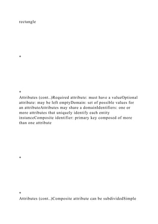
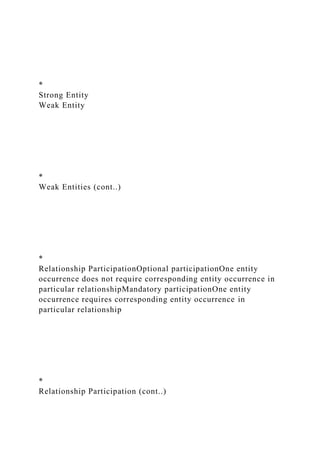
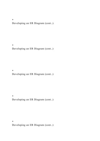
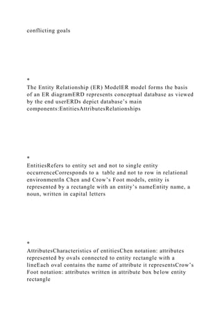
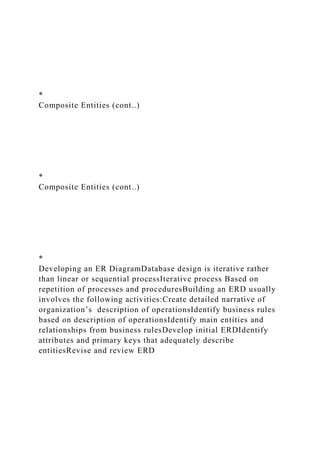
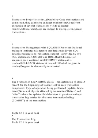
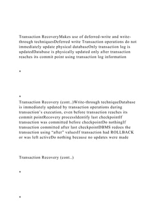
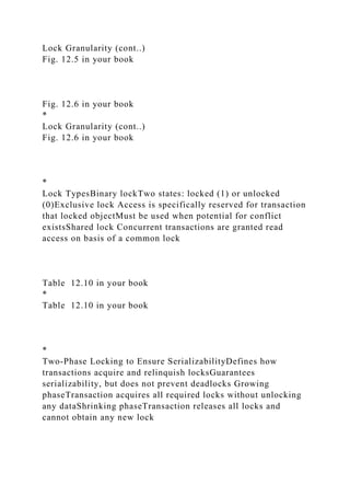
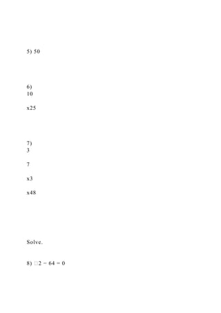
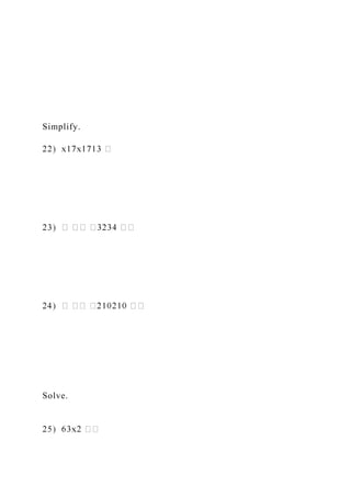
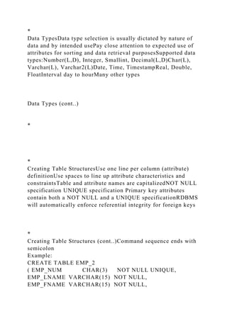
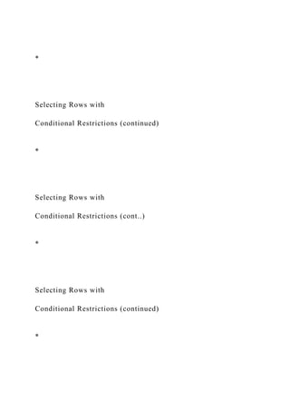
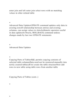
Restoring Table ContentsROLLBACKUsed to restore database
to its previous conditionOnly applicable if COMMIT command
has not been used to permanently store changes in
databaseSyntax:ROLLBACK;COMMIT and ROLLBACK only
work with manipulation commands that are used to add, modify,
or delete table rows
*
Deleting Table RowsDELETE Deletes a table rowSyntax:
DELETE FROM tablename
[WHERE conditionlist ];WHERE condition is optionalIf
WHERE condition is not specified, all rows from specified table
will be deleted
*
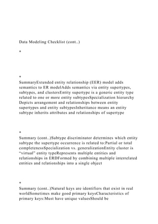
Inserting Table Rows with a
SELECT SubqueryINSERTInserts multiple rows from another
table (source)Uses SELECT subquerySubquery: query that is
embedded (or nested) inside another querySubquery is executed
firstSyntax:
INSERT INTO tablename SELECT columnlist FROM
tablename;
*](https://image.slidesharecdn.com/dbf-lecture11-chapter12-221226172622-96468150/85/DBF-Lecture11-Chapter12-pptDatabase-Principles-Fundam-docx-31-320.jpg)
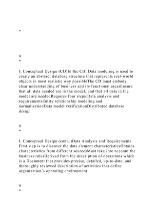
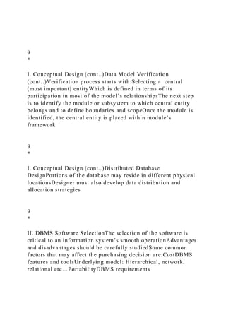
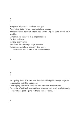
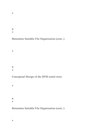
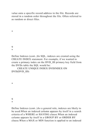
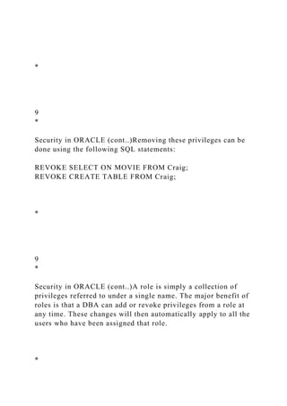
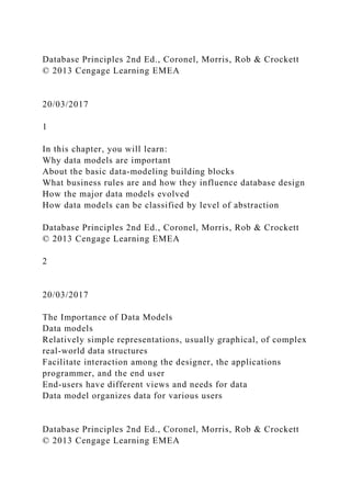
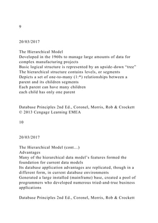
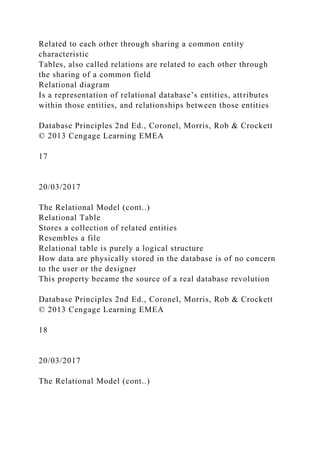
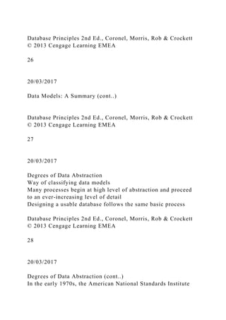
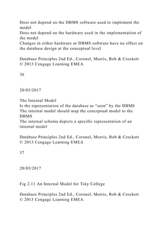
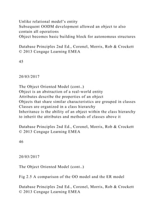
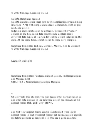
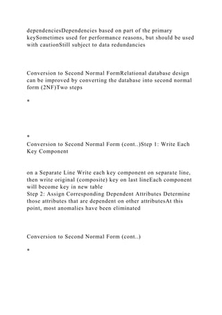
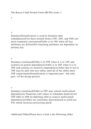
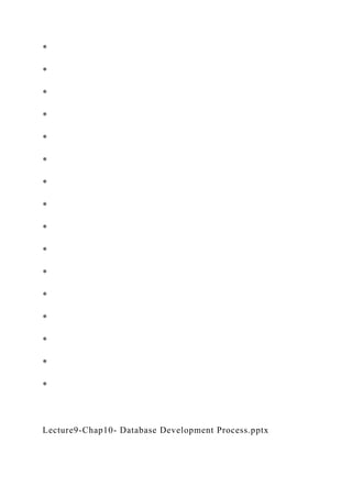
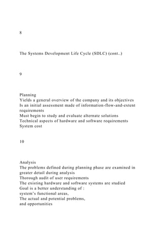
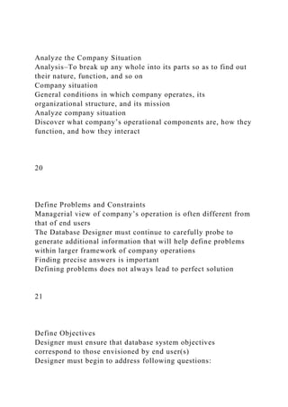
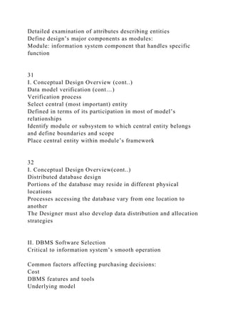
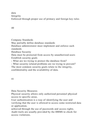
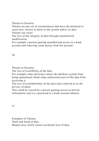
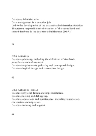
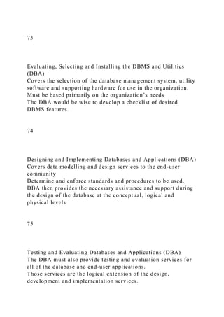
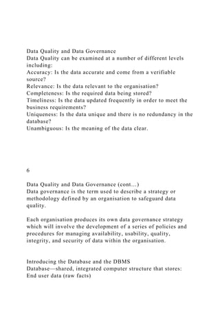
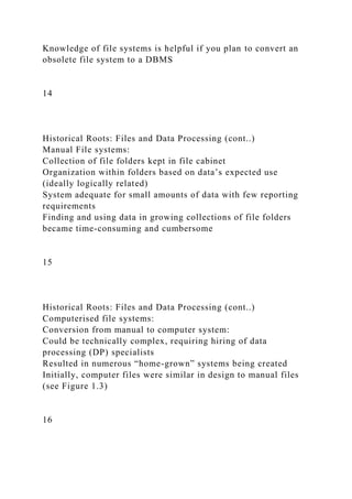
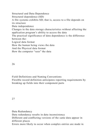
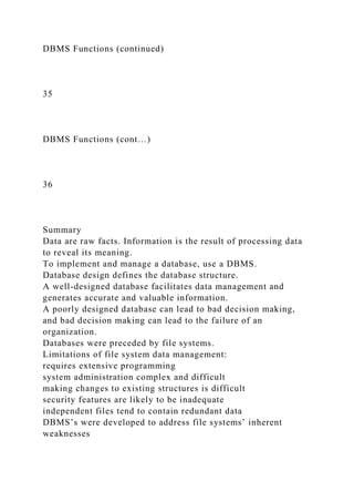
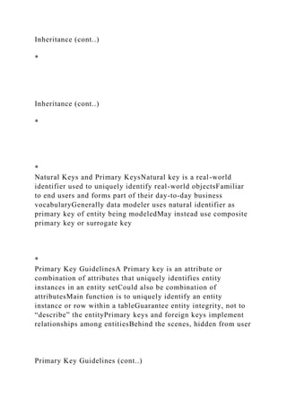
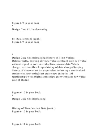
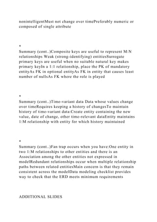
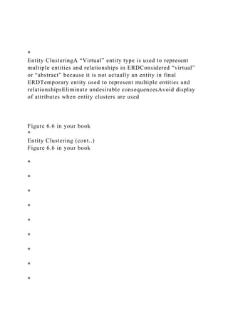
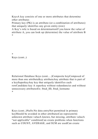
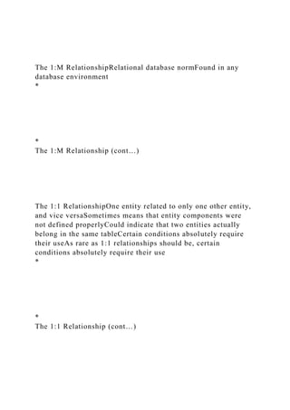
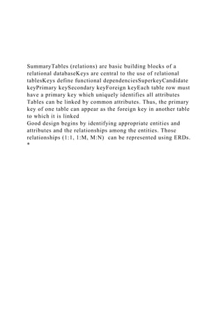
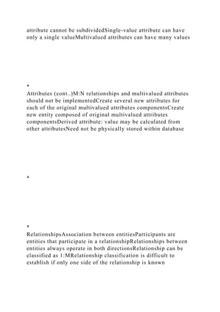
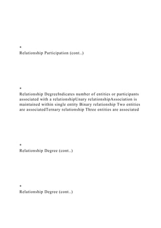
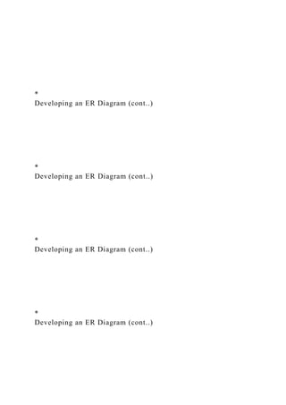
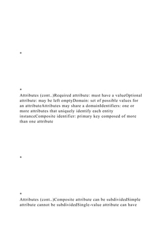
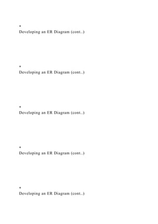
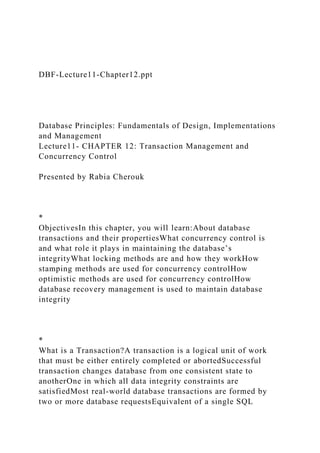
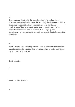
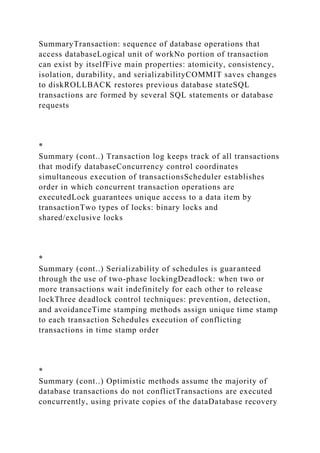
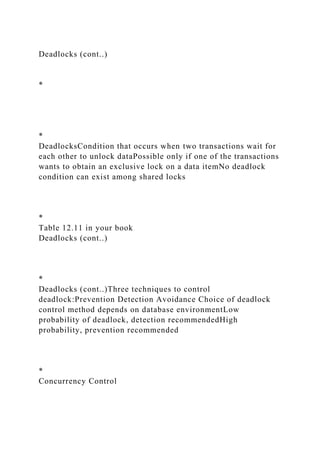
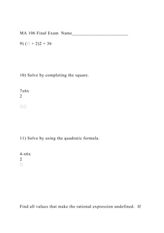
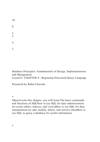
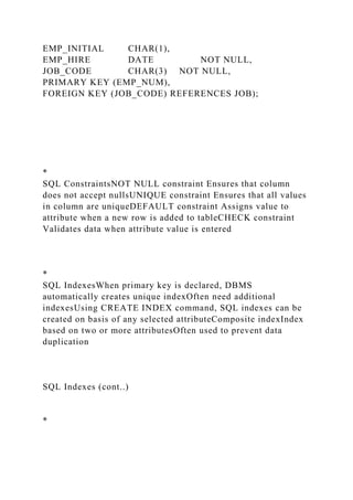
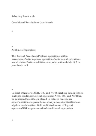
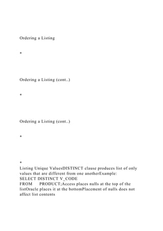
![SELECT QueriesFine-tune SELECT command by adding
restrictions to search criteria using:Conditional
restrictionsArithmetic operatorsLogical operatorsSpecial
operators
*
Selecting Rows with
Conditional RestrictionsSelect partial table contents by placing
restrictions on rows to be included in outputAdd conditional
restrictions to SELECT statement, using WHERE clauseSyntax:
SELECT columnlist
FROM tablelist
[ WHERE conditionlist ] ;
Selecting Rows with
Conditional Restrictions (continued)
*
Selecting Rows with
Conditional Restrictions (continued)](https://image.slidesharecdn.com/dbf-lecture11-chapter12-221226172622-96468150/85/DBF-Lecture11-Chapter12-pptDatabase-Principles-Fundam-docx-32-320.jpg)
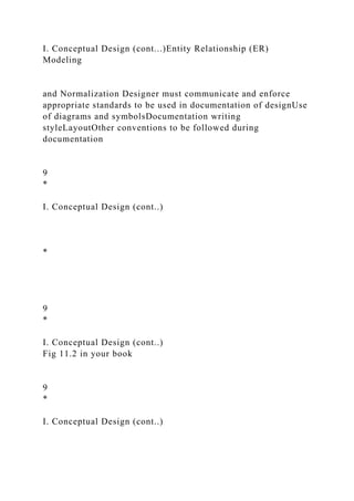
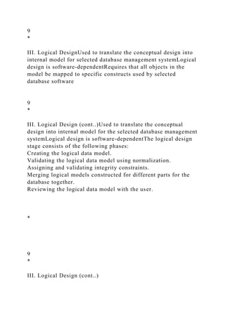
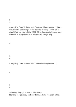
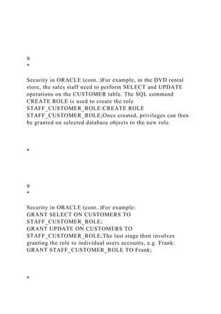
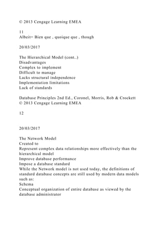
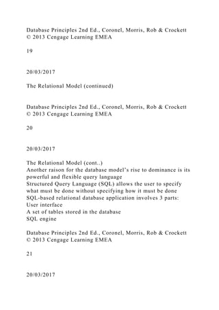
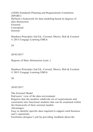
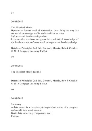
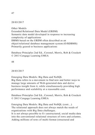
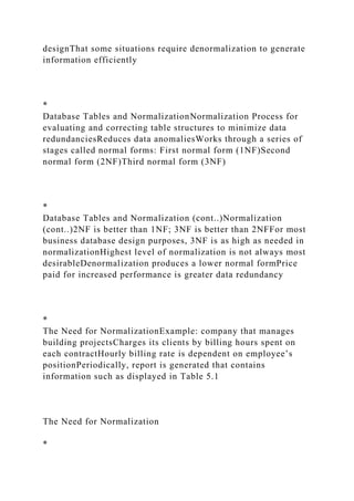
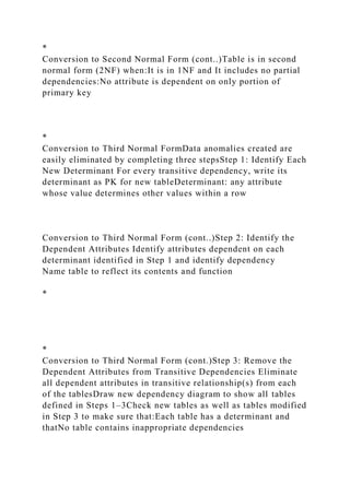
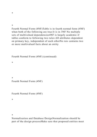
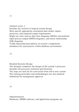
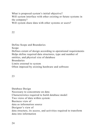
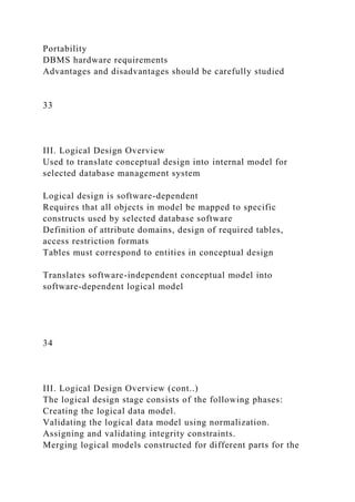
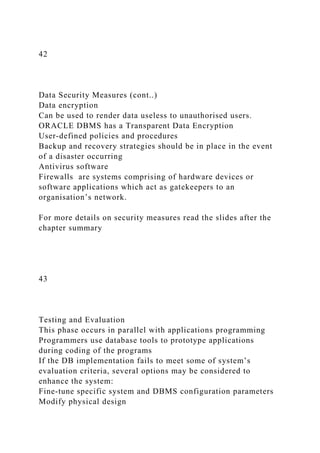
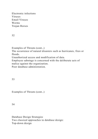
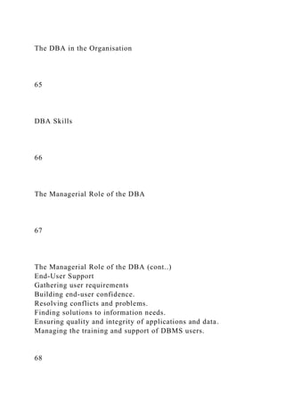
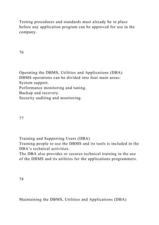
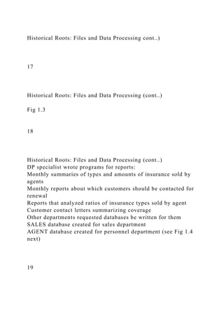
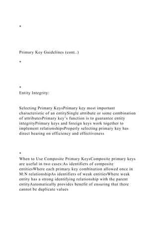
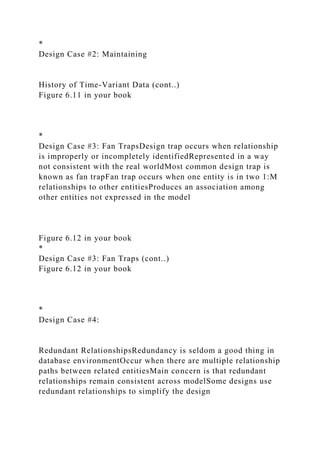
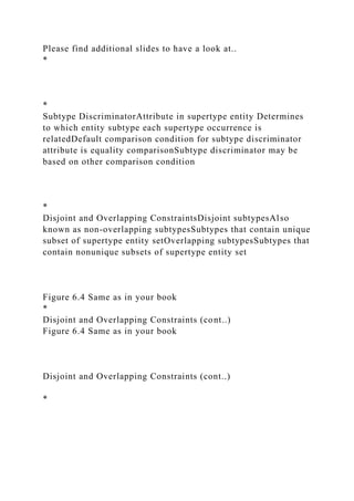
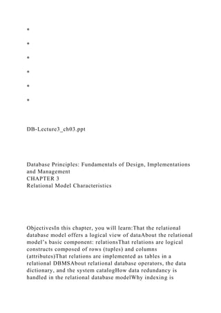
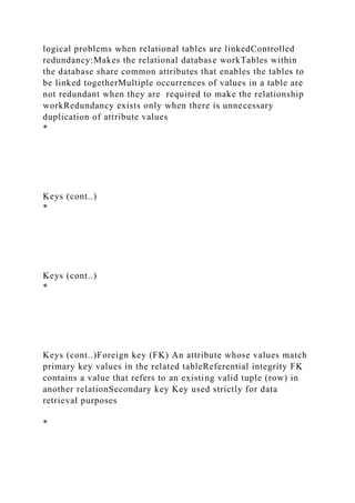
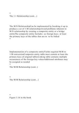
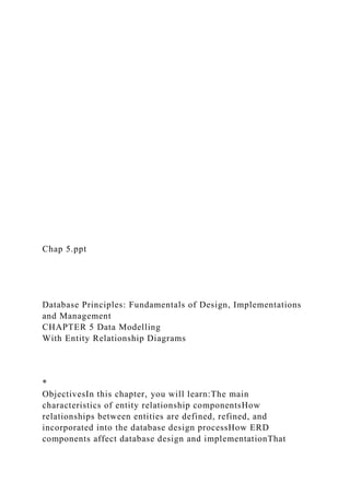
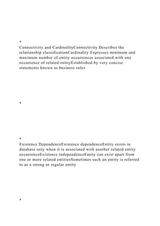
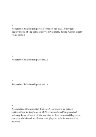
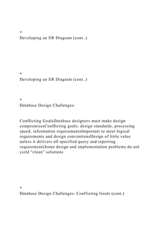
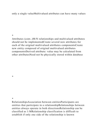
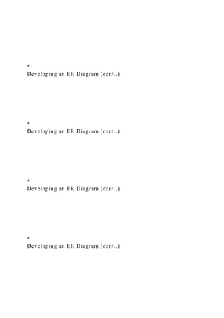
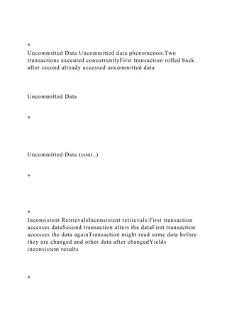
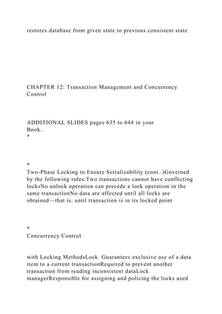
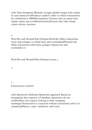
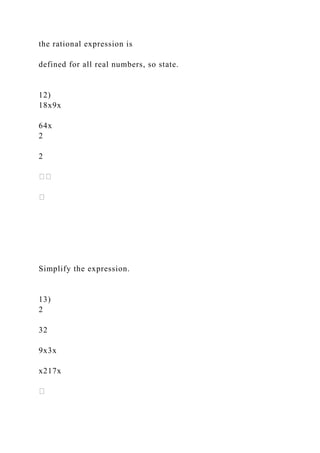
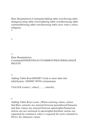
![Adding Primary and Foreign Key DesignationsWhen table is
copied, integrity rules do not copyPrimary and foreign keys
manually defined on new tableUser ALTER TABLE
commandSyntax:
ALTER TABLE tablename
ADD PRIMARY KEY (fieldname);For foreign key, use
FOREIGN KEY in place of PRIMARY KEY
*
Deleting a Table from the DatabaseDROPDeletes table from
databaseSyntax:
DROP TABLE tablename;Can drop a table only if it is not the
“one” side of any relationshipOtherwise RDBMS generates an
error messageForeign key integrity violation
*
Advanced SELECT QueriesLogical operators work well in the
query environmentSQL provides useful functions
that:CountFind minimum and maximum valuesCalculate
averages, etc.SQL allows user to limit queries to:Entries having
no duplicatesEntries whose duplicates may be grouped
*
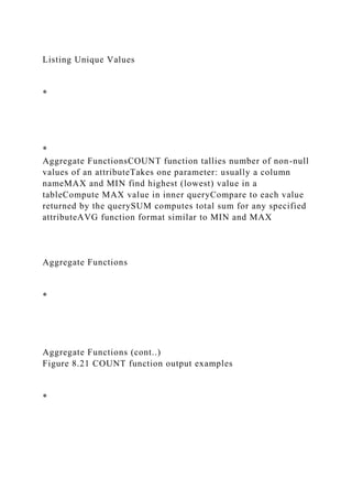
Ordering a ListingORDER BY clause useful when listing order
importantSyntax:
SELECT columnlist
FROM tablelist
[WHERE conditionlist]
[ORDER BY columnlist [ASC | DESC]];Ascending order
by default](https://image.slidesharecdn.com/dbf-lecture11-chapter12-221226172622-96468150/85/DBF-Lecture11-Chapter12-pptDatabase-Principles-Fundam-docx-39-320.jpg)
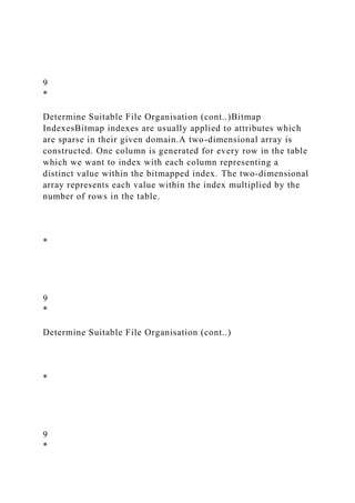
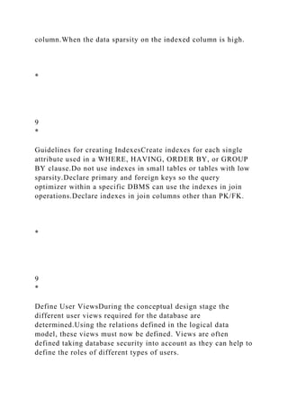
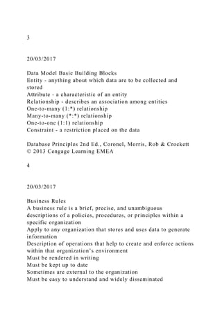
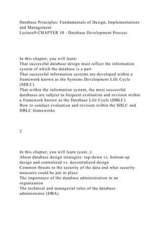
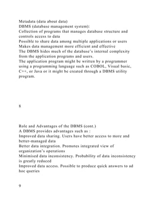
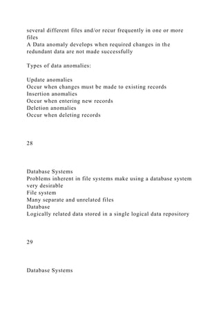
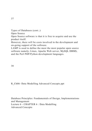
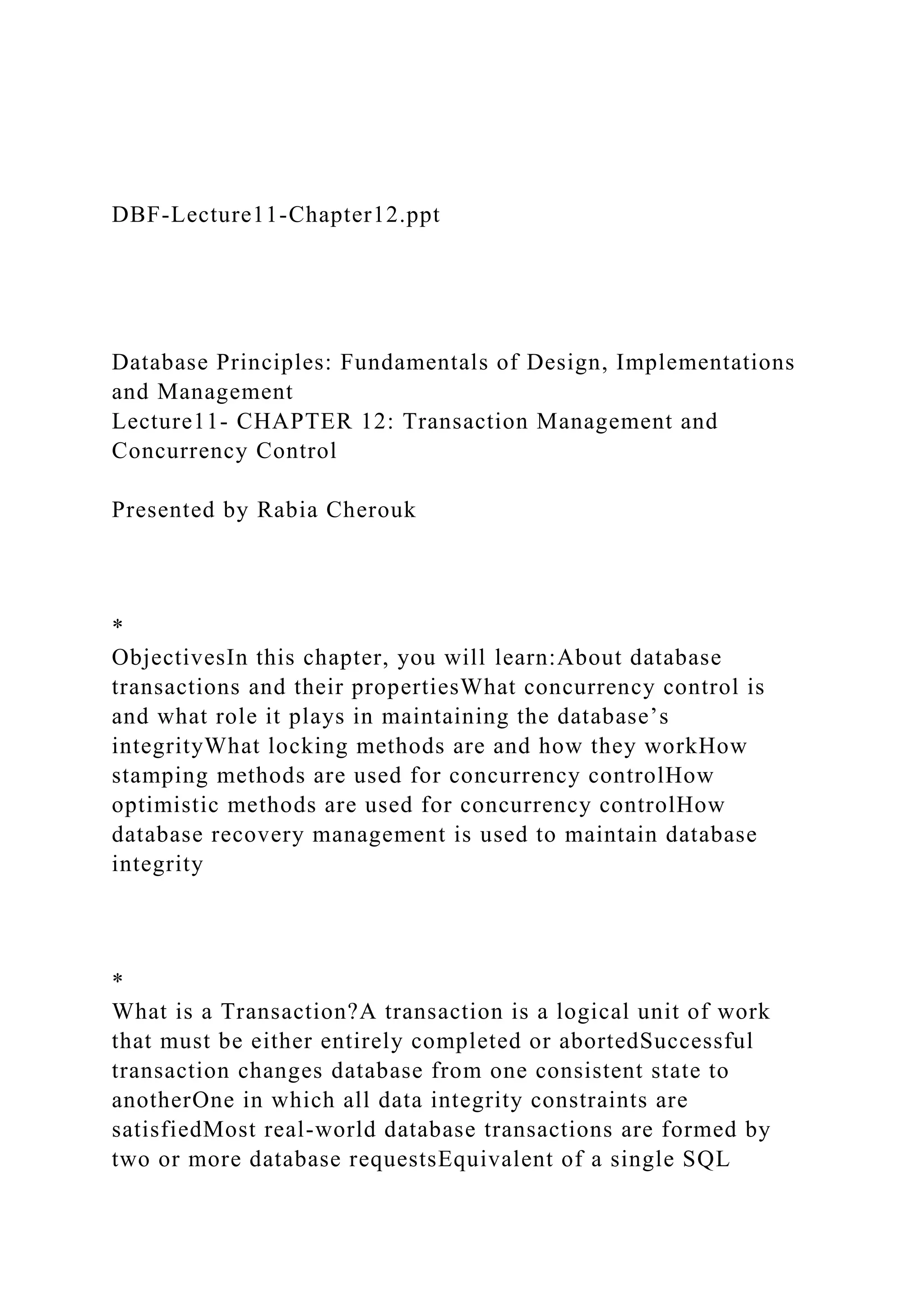
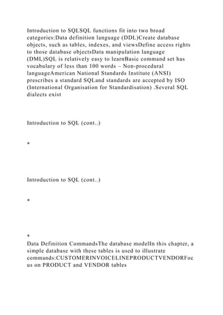
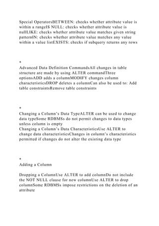
![Aggregate Functions (cont..)
Figure 8.22 MIN and MAX Output Examples
*
Aggregate Functions (cont..)
Figure 8.23 The total values of all items in the PRODUCT table
*
Aggregate Functions (cont..)
Figure 8.24 AVG Function Output Examples
*
*
Grouping DataFrequency distributions created by GROUP BY
clause within SELECT statementSyntax:
SELECT columnlist
FROM tablelist
[WHERE conditionlist]
[GROUP BY columnlist]
[HAVINGconditionlist]
[ORDER BY columnlist [ASC | DESC] ] ;](https://image.slidesharecdn.com/dbf-lecture11-chapter12-221226172622-96468150/85/DBF-Lecture11-Chapter12-pptDatabase-Principles-Fundam-docx-42-320.jpg)