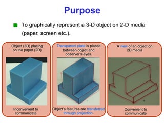
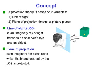
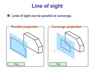
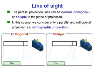
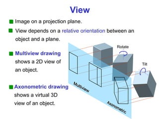
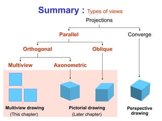
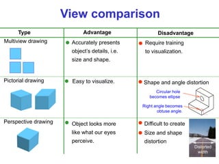
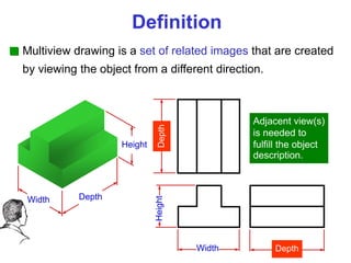
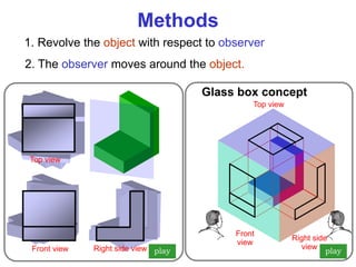
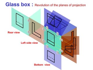
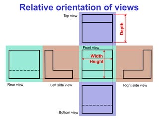
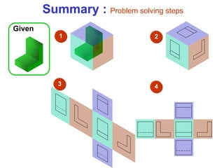
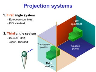
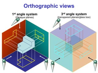
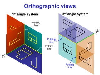
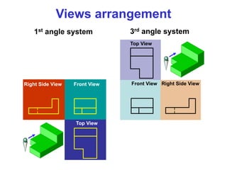
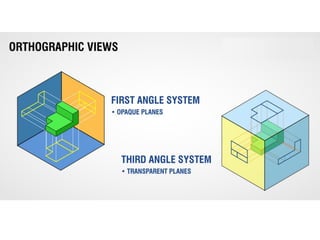
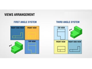
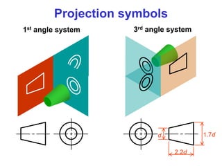
Chapter 3
Orthographic
Projection
Line convention
Multiview drawing
Projection theory
Contents
Projection
Thoery
Contents
Purpose
To graphically represent a 3-D object on 2-D media
(paper, screen etc.).
Object (3D) placing
on the paper (2D)
Transparent plate is placed
between object and
observer’s eyes.
Object’s features are transferred
through projection.
Inconvenient to
communicate
A view of an object on
2D media
Convenient to
communicate
Concept
A projection theory is based on 2 variables:
1) Line of sight
2) Plane of projection (image or picture plane)
Plane of projection
is an imaginary flat plane upon
which the image created by the
LOS is projected.
Line of sight (LOS)
is an imaginary ray of light
between an observer’s eye
and an object.
Line of sight
Lines of sight can be parallel or converge.
Converge projection
Parallel projection
Play Play
Line of sight
The parallel projection lines can be normal (orthogonal)
or oblique to the plane of projection.
Oblique
Orthogonal
Play Play
In this course, we consider only a parallel and orthogonal
projection, i.e. orthographic projection.
Image on a projection plane.
Rotate
Tilt
Multiview drawing
shows a 2D view of
an object.
Axonometric drawing
shows a virtual 3D
view of an object.
View
View depends on a relative orientation between an
object and a plane.
Summary : Types of views
Projections
Converge
Parallel
Orthogonal Oblique
Axonometric
Multiview
Pictorial drawing Perspective
drawing
Multiview drawing
(Later chapter)
(This chapter)
View comparison
Pictorial drawing
Perspective drawing
Multiview drawing
Difficult to create
Easy to visualize. Shape and angle distortion
Object looks more
like what our eyes
perceive.
Size and shape
distortion
Right angle becomes
obtuse angle.
Circular hole
becomes ellipse
Distorted
width
Accurately presents
object’s details, i.e.
size and shape.
Require training
to visualization.
Advantage Disadvantage
Type
Multiview
drawing
Contents
Multiview drawing is a set of related images that are created
by viewing the object from a different direction.
Definition
Width Depth
Height
Width
Height
Depth
Depth
Adjacent view(s)
is needed to
fulfill the object
description.
1. Revolve the object with respect to observer
Methods
2. The observer moves around the object.
Front view Right side view
Top view
Right side
view
Top view
play play
Front
view
Glass box concept
Glass box : Revolution of the planes of projection
Bottom view
Left side view
Rear view
Height
Width
Depth
Relative orientation of views
Left side view Right side view
Bottom view
Top view
Rear view
Front view
Summary : Problem solving steps
1 2
3 4
Given
Object features
Edge is a line that represent the boundary between two
faces of an object.
Surface limit is a line that represents the last visible
part of the curve surface.
Prism Cylinder Sphere
No edges!
Surface is an area that are bounded by edges or surface
limit. Surface can be plane or curve.
These features will appear as lines in a multiview drawing.
Note
Alignment
of views
Contents
Projection systems
1. First angle system
2. Third angle system
First
quadrant
Third
quadrant
- European countries
- ISO standard
- Canada, USA,
Japan, Thailand
Transparent
planes Opaque
planes
1st angle system
(Opaque planes)
3rd angle system
(transparent planes/glass box)
Orthographic views
Folding
line
Folding
line
Folding
line
Folding
line
1st angle system 3rd angle system
Orthographic views
1st angle system 3rd angle system
Front View Front View
Right Side View Right Side View
Top View
Top View
Views arrangement
Projection symbols
1st angle system 3rd angle system
d 1.7d
2.2d

Day 02 -Orthographic drawing.pdf

  • 1.
  • 2.
  • 3.
  • 4.
    Purpose To graphically representa 3-D object on 2-D media (paper, screen etc.). Object (3D) placing on the paper (2D) Transparent plate is placed between object and observer’s eyes. Object’s features are transferred through projection. Inconvenient to communicate A view of an object on 2D media Convenient to communicate
  • 5.
    Concept A projection theoryis based on 2 variables: 1) Line of sight 2) Plane of projection (image or picture plane) Plane of projection is an imaginary flat plane upon which the image created by the LOS is projected. Line of sight (LOS) is an imaginary ray of light between an observer’s eye and an object.
  • 6.
    Line of sight Linesof sight can be parallel or converge. Converge projection Parallel projection Play Play
  • 7.
    Line of sight Theparallel projection lines can be normal (orthogonal) or oblique to the plane of projection. Oblique Orthogonal Play Play In this course, we consider only a parallel and orthogonal projection, i.e. orthographic projection.
  • 8.
    Image on aprojection plane. Rotate Tilt Multiview drawing shows a 2D view of an object. Axonometric drawing shows a virtual 3D view of an object. View View depends on a relative orientation between an object and a plane.
  • 9.
    Summary : Typesof views Projections Converge Parallel Orthogonal Oblique Axonometric Multiview Pictorial drawing Perspective drawing Multiview drawing (Later chapter) (This chapter)
  • 10.
    View comparison Pictorial drawing Perspectivedrawing Multiview drawing Difficult to create Easy to visualize. Shape and angle distortion Object looks more like what our eyes perceive. Size and shape distortion Right angle becomes obtuse angle. Circular hole becomes ellipse Distorted width Accurately presents object’s details, i.e. size and shape. Require training to visualization. Advantage Disadvantage Type
  • 11.
  • 12.
    Multiview drawing isa set of related images that are created by viewing the object from a different direction. Definition Width Depth Height Width Height Depth Depth Adjacent view(s) is needed to fulfill the object description.
  • 13.
    1. Revolve theobject with respect to observer Methods 2. The observer moves around the object. Front view Right side view Top view Right side view Top view play play Front view Glass box concept
  • 14.
    Glass box :Revolution of the planes of projection Bottom view Left side view Rear view
  • 15.
    Height Width Depth Relative orientation ofviews Left side view Right side view Bottom view Top view Rear view Front view
  • 16.
    Summary : Problemsolving steps 1 2 3 4 Given
  • 17.
    Object features Edge isa line that represent the boundary between two faces of an object. Surface limit is a line that represents the last visible part of the curve surface. Prism Cylinder Sphere No edges! Surface is an area that are bounded by edges or surface limit. Surface can be plane or curve. These features will appear as lines in a multiview drawing. Note
  • 18.
  • 19.
    Projection systems 1. Firstangle system 2. Third angle system First quadrant Third quadrant - European countries - ISO standard - Canada, USA, Japan, Thailand Transparent planes Opaque planes
  • 20.
    1st angle system (Opaqueplanes) 3rd angle system (transparent planes/glass box) Orthographic views
  • 21.
  • 22.
    1st angle system3rd angle system Front View Front View Right Side View Right Side View Top View Top View Views arrangement
  • 25.
    Projection symbols 1st anglesystem 3rd angle system d 1.7d 2.2d