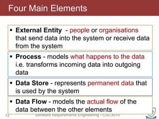
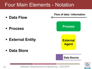
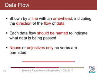
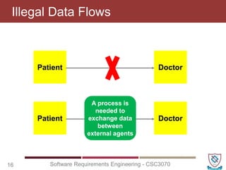
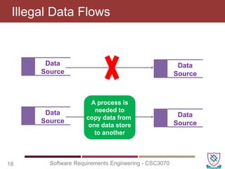
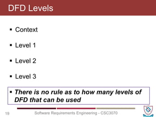
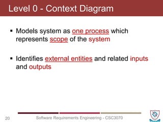
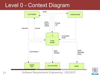
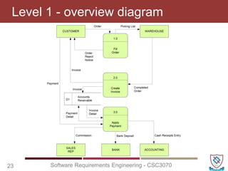
Software Requirements Engineering
CSC3070
Lecture No. 19
Muhammad Shahid
Department of Computer Science
National Textile University
shahid.abdullah@hotmail.com
 Activity Diagrams
 Activity Diagrams - Symbols
 Activity Diagrams - Examples
 Swinlane vs. Non-Swinlane
 Activity Diagrams - Task
Last Lecture Review
2 Software Requirements Engineering - CSC3070
Agenda – What will you Learn Today?
3 Software Requirements Engineering - CSC3070
Data Flow Diagram
4 Software Requirements Engineering - CSC3070
Data Flow Diagram (DFD)
Elements of the Analysis Model
5 Software Requirements Engineering - CSC3070
Structured Analysis
Object-Oriented Analysis
Scenario-Based Modeling
Use Case Text
Use Case Diagrams
Activity Diagrams
Swim Lane Diagrams
Flow-Oriented Modeling
Data Structure Diagrams
Data Flow Diagrams
Control-flow Diagrams
Processing Narratives
Class-Based Modeling
Class Diagrams
Analysis Packages
CRC Models
Collaboration Diagrams
Behavioral Modeling
State Diagrams
Sequence Diagrams
 A way to model a real world situation
 They are the interface between the real world
activities and an understanding of how this
can be converted into a computer system
What is a Data Flow Diagram?
6 Software Requirements Engineering - CSC3070
 It is a way of taking the physical view (all
documents involved) and converting it into a
logical view (the data they contain)
 Their main purpose is to communicate with
the user, the analyst’s understanding of the
scope of the required system
Why do We Use DFDs?
7 Software Requirements Engineering - CSC3070
 Life Cycle Phases
 Planning
 Feasibility Study
 Analysis
 Design
 Code and Unit test
Where Do They Fit In?
8 Software Requirements Engineering - CSC3070
 Life Cycle Phases
 Planning
 Feasibility Study
 Analysis
 Design
 Code and Unit test
Where Do They Fit In?
9 Software Requirements Engineering - CSC3070
 Analysis (What do we
do?)
– Fact finding
o investigate business
process and the current
system
– modelling the current and
required systems
– deliverables -
o requirements specification
o logical models of the
required system
 DFDs describe the flow of data or
information into and out of a system
 What does the system do to the data?
 A DFD is a graphic representation of the flow
of data or information through a system
Data Flow Diagrams (DFD)
10 Software Requirements Engineering - CSC3070
 What does the system do to the data?
 Decomposition - Divide and subdivide into
manageable size problems
Decomposition & Abstraction
11 Software Requirements Engineering - CSC3070
 Abstraction - Concentrate on the important
issues and ignore the irrelevant
 External Entity - people or organisations
that send data into the system or receive data
from the system
Four Main Elements
12 Software Requirements Engineering - CSC3070
 Process - models what happens to the data
i.e. transforms incoming data into outgoing
data
 Data Store - represents permanent data that
is used by the system
 Data Flow - models the actual flow of the
data between the other elements
 Data Flow
 Process
 External Entity
 Data Store
Four Main Elements - Notation
13 Software Requirements Engineering - CSC3070
Process
Flow of data / information
External
Agent
Data Source
 Is anything outside the system that is of
interest to the system
 Can be a person, a company or another
system
Outside Entity
14 Software Requirements Engineering - CSC3070
Outside entity shows the Name
and a lowercase alpha character
is used to uniquely identify it.
Customer
a
If an outside entity is
repeated for the purpose of
neat layout a line is added
across the top.
Customer
a
 Shown by a line with an arrowhead, indicating
the direction of the flow of data
 Each data flow should be named to indicate
what data is being passed
 Nouns or adjectives only no verbs are
permitted
Data Flow
15 Software Requirements Engineering - CSC3070
Illegal Data Flows
16 Software Requirements Engineering - CSC3070
Patient Doctor
Patient Doctor
A process is
needed to
exchange data
between
external agents
Illegal Data Flows
17 Software Requirements Engineering - CSC3070
Patient
Patient
A process is
needed to
update a data
store
Data
Source
Data
Source
Illegal Data Flows
18 Software Requirements Engineering - CSC3070
Data
Source
Data
Source
Data
Source
Data
Source
A process is
needed to
copy data from
one data store
to another
 Context
 Level 1
 Level 2
 Level 3
DFD Levels
19 Software Requirements Engineering - CSC3070
 There is no rule as to how many levels of
DFD that can be used
 Models system as one process which
represents scope of the system
 Identifies external entities and related inputs
and outputs
Level 0 - Context Diagram
20 Software Requirements Engineering - CSC3070
Level 0 - Context Diagram
21 Software Requirements Engineering - CSC3070
 Utilizes all four elements
 Gives overview of full system
 Identifies major processes and data flows
and data stores that are used by the major
processes
 Boundary of level 1 is the context diagram
Level 1 - overview diagram
22 Software Requirements Engineering - CSC3070
Level 1 - overview diagram
23 Software Requirements Engineering - CSC3070
 A breakdown of a level 1 process
 Level 1 process is expanded into more detail
 Each process in level 1 is decomposed to
show its constituent processes
 Boundary of level 2 is the level 1 process
Level 2 - detailed diagram
24 Software Requirements Engineering - CSC3070
 Draw document flow diagram of the current
situation
 Draw a systems boundary around the agencies
that are part of the system
 Draw a Context Diagram
 Identify processes in the system
 Complete the level 1 Current Physical DFD
Procedure for Constructing DFD’s
25 Software Requirements Engineering - CSC3070
 Numbering
– On level 1 processes are numbered 1,2,3…
– On level 2 processes are numbered x.1, x.2,
x.3… where x is the number of the parent level 1
process
– Number is used to uniquely identify process not
to represent any order of processing
– Data store numbers usually D1, D2, D3...
Rules for DFDs
26 Software Requirements Engineering - CSC3070
 Labelling
– Process label - short description of what the
process does, e.g. Price order
– Data flow label - noun representing the data
flowing through it e.g. Customer payment
– Data store label - describes the type of data
stored
– Make labels as meaningful as possible
Rules for DFDs
27 Software Requirements Engineering - CSC3070
 Balancing
– Any data flows entering or leaving a parent level
must by equivalent to those on the child level
 Data Stores
– Data stores that are local to a process need not
be included until the process is expanded
Rules for DFDs
28 Software Requirements Engineering - CSC3070
 Data Flow Diagrams (DFD)
 Four Main Elements
– Data Flow
– Process
– External Entity
– Data Store
 DFD Levels
 Procedure for Constructing DFD’s
 Rules for DFDs
Recap
29 Software Requirements Engineering - CSC3070
Questions
30 Software Requirements Engineering - CSC3070

CSC3070 - Lecture 19 (Data Flow Diagram - I).pptx

  • 1.
    Software Requirements Engineering CSC3070 LectureNo. 19 Muhammad Shahid Department of Computer Science National Textile University shahid.abdullah@hotmail.com
  • 2.
     Activity Diagrams Activity Diagrams - Symbols  Activity Diagrams - Examples  Swinlane vs. Non-Swinlane  Activity Diagrams - Task Last Lecture Review 2 Software Requirements Engineering - CSC3070
  • 3.
    Agenda – Whatwill you Learn Today? 3 Software Requirements Engineering - CSC3070 Data Flow Diagram
  • 4.
    4 Software RequirementsEngineering - CSC3070 Data Flow Diagram (DFD)
  • 5.
    Elements of theAnalysis Model 5 Software Requirements Engineering - CSC3070 Structured Analysis Object-Oriented Analysis Scenario-Based Modeling Use Case Text Use Case Diagrams Activity Diagrams Swim Lane Diagrams Flow-Oriented Modeling Data Structure Diagrams Data Flow Diagrams Control-flow Diagrams Processing Narratives Class-Based Modeling Class Diagrams Analysis Packages CRC Models Collaboration Diagrams Behavioral Modeling State Diagrams Sequence Diagrams
  • 6.
     A wayto model a real world situation  They are the interface between the real world activities and an understanding of how this can be converted into a computer system What is a Data Flow Diagram? 6 Software Requirements Engineering - CSC3070
  • 7.
     It isa way of taking the physical view (all documents involved) and converting it into a logical view (the data they contain)  Their main purpose is to communicate with the user, the analyst’s understanding of the scope of the required system Why do We Use DFDs? 7 Software Requirements Engineering - CSC3070
  • 8.
     Life CyclePhases  Planning  Feasibility Study  Analysis  Design  Code and Unit test Where Do They Fit In? 8 Software Requirements Engineering - CSC3070
  • 9.
     Life CyclePhases  Planning  Feasibility Study  Analysis  Design  Code and Unit test Where Do They Fit In? 9 Software Requirements Engineering - CSC3070  Analysis (What do we do?) – Fact finding o investigate business process and the current system – modelling the current and required systems – deliverables - o requirements specification o logical models of the required system
  • 10.
     DFDs describethe flow of data or information into and out of a system  What does the system do to the data?  A DFD is a graphic representation of the flow of data or information through a system Data Flow Diagrams (DFD) 10 Software Requirements Engineering - CSC3070  What does the system do to the data?
  • 11.
     Decomposition -Divide and subdivide into manageable size problems Decomposition & Abstraction 11 Software Requirements Engineering - CSC3070  Abstraction - Concentrate on the important issues and ignore the irrelevant
  • 12.
     External Entity- people or organisations that send data into the system or receive data from the system Four Main Elements 12 Software Requirements Engineering - CSC3070  Process - models what happens to the data i.e. transforms incoming data into outgoing data  Data Store - represents permanent data that is used by the system  Data Flow - models the actual flow of the data between the other elements
  • 13.
     Data Flow Process  External Entity  Data Store Four Main Elements - Notation 13 Software Requirements Engineering - CSC3070 Process Flow of data / information External Agent Data Source
  • 14.
     Is anythingoutside the system that is of interest to the system  Can be a person, a company or another system Outside Entity 14 Software Requirements Engineering - CSC3070 Outside entity shows the Name and a lowercase alpha character is used to uniquely identify it. Customer a If an outside entity is repeated for the purpose of neat layout a line is added across the top. Customer a
  • 15.
     Shown bya line with an arrowhead, indicating the direction of the flow of data  Each data flow should be named to indicate what data is being passed  Nouns or adjectives only no verbs are permitted Data Flow 15 Software Requirements Engineering - CSC3070
  • 16.
    Illegal Data Flows 16Software Requirements Engineering - CSC3070 Patient Doctor Patient Doctor A process is needed to exchange data between external agents
  • 17.
    Illegal Data Flows 17Software Requirements Engineering - CSC3070 Patient Patient A process is needed to update a data store Data Source Data Source
  • 18.
    Illegal Data Flows 18Software Requirements Engineering - CSC3070 Data Source Data Source Data Source Data Source A process is needed to copy data from one data store to another
  • 19.
     Context  Level1  Level 2  Level 3 DFD Levels 19 Software Requirements Engineering - CSC3070  There is no rule as to how many levels of DFD that can be used
  • 20.
     Models systemas one process which represents scope of the system  Identifies external entities and related inputs and outputs Level 0 - Context Diagram 20 Software Requirements Engineering - CSC3070
  • 21.
    Level 0 -Context Diagram 21 Software Requirements Engineering - CSC3070
  • 22.
     Utilizes allfour elements  Gives overview of full system  Identifies major processes and data flows and data stores that are used by the major processes  Boundary of level 1 is the context diagram Level 1 - overview diagram 22 Software Requirements Engineering - CSC3070
  • 23.
    Level 1 -overview diagram 23 Software Requirements Engineering - CSC3070
  • 24.
     A breakdownof a level 1 process  Level 1 process is expanded into more detail  Each process in level 1 is decomposed to show its constituent processes  Boundary of level 2 is the level 1 process Level 2 - detailed diagram 24 Software Requirements Engineering - CSC3070
  • 25.
     Draw documentflow diagram of the current situation  Draw a systems boundary around the agencies that are part of the system  Draw a Context Diagram  Identify processes in the system  Complete the level 1 Current Physical DFD Procedure for Constructing DFD’s 25 Software Requirements Engineering - CSC3070
  • 26.
     Numbering – Onlevel 1 processes are numbered 1,2,3… – On level 2 processes are numbered x.1, x.2, x.3… where x is the number of the parent level 1 process – Number is used to uniquely identify process not to represent any order of processing – Data store numbers usually D1, D2, D3... Rules for DFDs 26 Software Requirements Engineering - CSC3070
  • 27.
     Labelling – Processlabel - short description of what the process does, e.g. Price order – Data flow label - noun representing the data flowing through it e.g. Customer payment – Data store label - describes the type of data stored – Make labels as meaningful as possible Rules for DFDs 27 Software Requirements Engineering - CSC3070
  • 28.
     Balancing – Anydata flows entering or leaving a parent level must by equivalent to those on the child level  Data Stores – Data stores that are local to a process need not be included until the process is expanded Rules for DFDs 28 Software Requirements Engineering - CSC3070
  • 29.
     Data FlowDiagrams (DFD)  Four Main Elements – Data Flow – Process – External Entity – Data Store  DFD Levels  Procedure for Constructing DFD’s  Rules for DFDs Recap 29 Software Requirements Engineering - CSC3070
  • 30.