Download to read offline
![K. Sushmaja, Dr. Fazal Noorbasha / International Journal of Engineering Research and
Applications (IJERA) ISSN: 2248-9622 www.ijera.com
Vol. 3, Issue 2, March -April 2013, pp.392-395
Fault Detection with Error Correction Codes for Memory
Applications
K. Sushmaja1 , Dr. Fazal Noorbasha2
1
(M. Tech student, Department of Electronics and Communication Engineering, K L University,
Vaddeswaram, Guntur Dt.)
2
(Assoc. Prof, Department of Electronics and Communication Engineering, K L University, Vaddeswaram,
Guntur Dt.)
ABSTRACT
The paper deals with error detection with high error correction capability and are linear
method for difference set cyclic codes with cyclic block codes.
majority logic decoding. These are suitable for
memory applications due to their capability to 1.2 DSCC
correct large number of errors. The proposed DSCCs are one-step ML decodable codes with high
Majority Logic decoder itself detects failures error-correction capability and are linear cyclic
which minimize area overhead and power block codes[5].
consumption. The memory access time is also 1) Perfect Difference Set: DSCCs work on the
reduced when there is no error in the data read. difference-set concept for which a brief description
The proposed circuit is simulated in DSCH, follows. Given a set and a difference of the
Cadence- Virtuoso, and Xilinx. The results elements, we have
obtained in various tools are presented in this P = {l0, l1… q} (0<= l1 < l2 …… <lq <=(q+1))
paper. D = {li – lj; i=! j}
2) DSCC Construction: For a binary code, the
perfect difference-set is constructed using the
Keywords – Difference set cyclic codes, Error
relationship
Correction Codes (ECC), Majority Logic decoder
q= 2s : s ε N
3) DSCC Parameters: Besides from the definitions
I. INTRODUCTION and equations previously explained, the following
Memory applications should be protected
parameters completely define the DSCC codes:
from all kinds of faults for reliable performance.
• Code length: 22s + 2s + 1
Those faults can be detected using Error Correction
• Message bits: 22s + 2s + 3s
Codes (ECC). When digital data is stored in a
• Parity-check bits: 3s + 1
memory, it is crucial to have a mechanism that can
• Minimum distance: d = 2s + 2
detect and correct a certain number of errors. ECC
encodes data in such a way that a decoder can
identify and correct certain errors in the data. II. MAJORITY LOGIC DECODER (MLD)
MLD is based on a number of parity check
Usually data strings are encoded by adding a
equations which are orthogonal to each other, so
number of redundant bits to them. When the
that, at each iteration, each code word bit only
original data is reconstructed a decoder examines
the encoded message, to check for any errors. participates in one parity check equation, except the
very first bit which contributes to all equations. For
this reason, the majority result of these parity check
1.1 Error Correction Codes (ECC)
There are 2 basic types of Error Correction Codes: equations decide the correctness of the current bit
under decoding.
Block codes, which are referred to as (n,k)
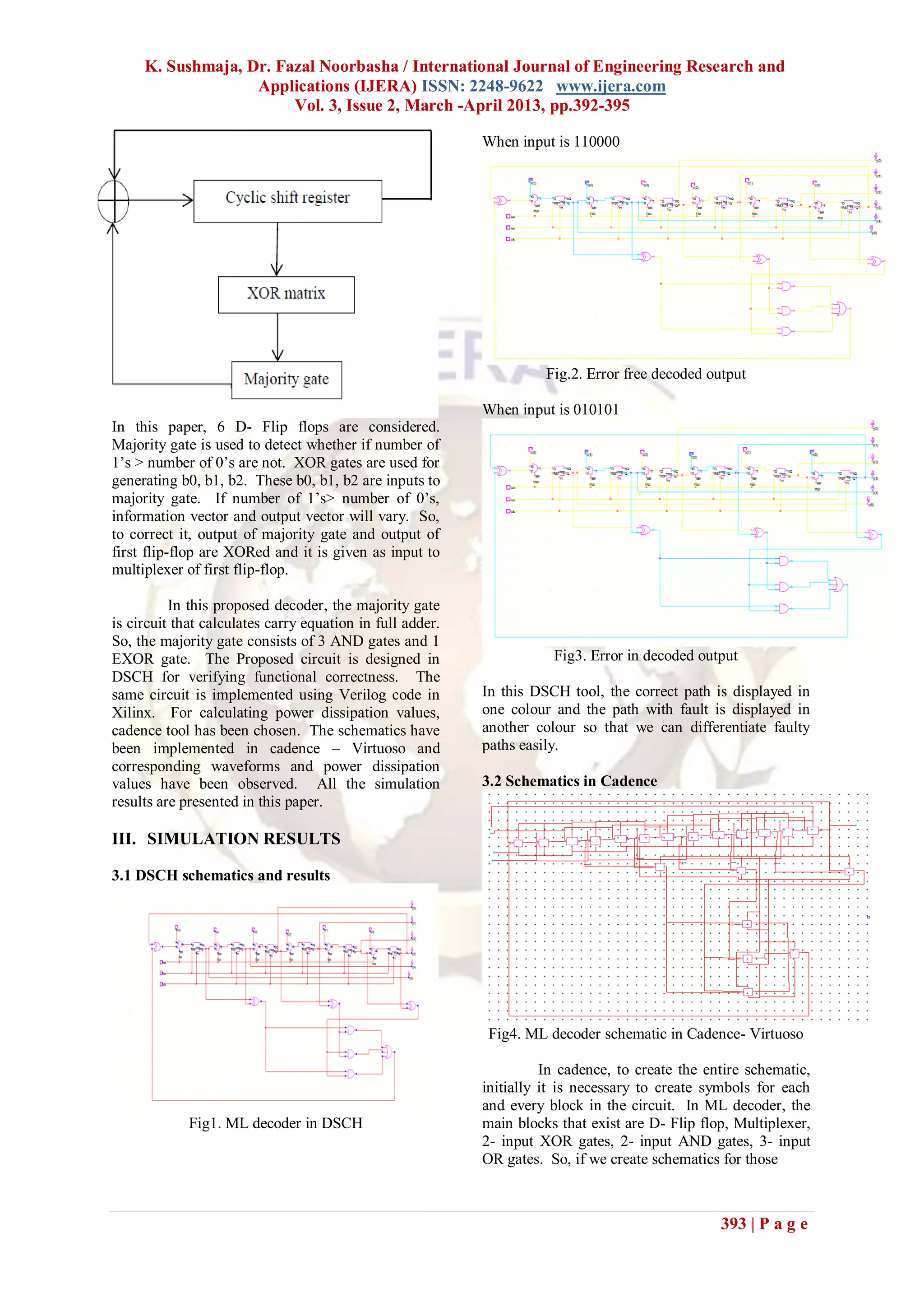
ML decoder is a simple and powerful
codes.
decoder, capable of correcting multiple random bit-
Convolution codes, where the code words flips depending on the number of parity check
produced depend on both the data message and a
equations. It consists of four parts:
given number of previously encoded messages.
1) a cyclic shift register
Among the ECC codes that meet the requirements 2) an EXOR matrix
of higher error correction capability and low 3) a majority gate
decoding complexity, cyclic block codes have been
4) an XOR for correcting the code word bit under
identified as good one, due to their property of being decoding.
Majority Logic (ML) decodable. LDPC (Low
Density Parity Check) codes belong to the family of
ML decodable codes. Difference Set Cyclic Codes
(DSCC), one specific type of LDPC codes are used
here. DSCCs are one step ML decodable codes
392 | P a g e](https://image.slidesharecdn.com/bj32392395-130322064210-phpapp01/75/Bj32392395-1-2048.jpg)

![K. Sushmaja, Dr. Fazal Noorbasha / International Journal of Engineering Research and
Applications (IJERA) ISSN: 2248-9622 www.ijera.com
Vol. 3, Issue 2, March -April 2013, pp.392-395
that helped me in successful completion of this
report.
REFERENCES
[1] Shih-Fu Liu, “ Efficient Majority Logic
Fault Detection With Difference-Set Codes
for Memory Applications”, IEEE
transactions on very large scale integration
(VLSI) systems, vol. 20, no. 1, january
2012
[2] S. Lin and D. J. Costello, Error Control
Coding, 2nd ed. Englewood Cliffs, NJ:
Prentice-Hall, 2004.
[3] S. Reed, “A class of multiple-error-
correcting codes and the decoding
scheme,” IRE Trans. Inf. Theory, vol. IT-4,
pp. 38–49, 1954.
[4] H. Naeimi and A. DeHon, “Fault secure
encoder and decoder for NanoMemory
applications,” IEEE Trans. Very Large
Scale Integr. (VLSI) Syst., vol. 17, no. 4,
pp. 473–486, Apr. 2009.
[5] Y. Kato and T. Morita, “Error correction
circuit using difference-set cyclic code,” in
Proc. ASP-DAC, 2003, pp. 585–586.
395 | P a g e](https://image.slidesharecdn.com/bj32392395-130322064210-phpapp01/75/Bj32392395-4-2048.jpg)

The paper presents a fault detection mechanism utilizing Difference Set Cyclic Codes (DSCC) to enhance error correction capabilities in memory applications. It describes the implementation of majority logic decoding techniques that allow for the correction of multiple errors while minimizing power consumption and access time. Simulation results are provided to validate the proposed circuit design using tools such as Cadence and Xilinx.