Download to read offline
![IJRET: International Journal of Research in Engineering and Technology eISSN: 2319-1163 | pISSN: 2321-7308
_______________________________________________________________________________________
Volume: 03 Special Issue: 01 | NC-WiCOMET-2014 | Mar-2014, Available @ http://www.ijret.org 65
MAGICUS CLOCK
Geethu Issac1
, Veena Thomas 2
, Geena P George3
, Rufeena Abu4
, Shainy Peter5
1,2,3,4
B.Tech student, 5
Assistant Professor, ECE, MBITS, Nellimattom, Kerala, India
Abstract
From the world famous series-Harry Potter, written by the British author Miss J.K Rowling, we do come across a ‘magical clock’-one
of the curious Weasley house holding. Inspired from the same, the magical clock that we have desired to create is a repurposed
grandfather clock, modified with gearing that allows four hands to rotate 360 degrees. Faces or clock hands indicate people, with
locations instead of times. Then the clock is attached with a microcontroller that would watch for updates on and turn the hands
appropriately. This project requires zigbee modules which transmit different signal to be placed on different location of the building,
another zigbee module which can be used as a hand set for a person to be tracked and also there is a server system having zigbee
module, PIC and stepper motor which receives the signal from handset and move the needle of clock accordingly with the help of
stepper motor.
Keywords: PIC- Peripheral Inter phase Controller, IC.
----------------------------------------------------------------------***------------------------------------------------------------------------
1. INTRODUCTION
The main objective of our project is to track people and
display their location on the dial of a clock. The needles of the
clock will represent people and different sectors of the clock
will represent different location. Our model will track a single
person and identifies three locations.
This is done with the help of programmed PIC [1]
microcontrollers, zigbee [2] modules and stepper motors [3].
This project requires zigbee modules which transmit different
signal to be placed on different location of the building,
another zigbee module which can be used as a hand set for a
person to be tracked and also there is a server system having
zigbee module, PIC and stepper motor which receives the
signal from handset and move the needle of clock accordingly
with the help of stepper motor.
Our device can be used as a gadget at home, offices and other
busy institutions. With this anybody can know the position of
a person without difficulty
2. SYSTEM DESCRIPTIPON
2.1 Existing System
In this system location of a person in a large building should
be tracked manually .It requires lot of time to search for a
single person in each and every room of a building. It is less
efficient and has loss of energy.
2.2 Proposed System
In this system location can be easily tracked out by just
looking in a clock. It requires fewer fractions of seconds to
track a person on large building. It is highly efficient and has
no loss of human energy.
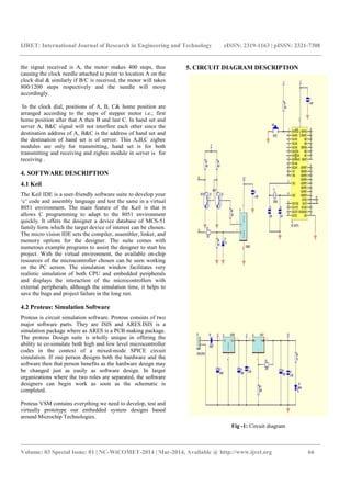
3. BLOCK DIAGRAM OF MAGICUS CLOCK
Chart -1: System block diagram
In Magicus Clock five modules are used, each module
contains a programmed PIC microcontroller and a zigbee
module. Three modules are kept at three rooms via A, B, C.
One module is kept at hand set, which is mobile and the fifth
module is attached with the clock dial. The three stationary
modules kept at three different rooms shall continuously
transmit signals A, B, C. When the hand module is at near
proximity to any one of them, it receives the signal and
retransmits the signal to the clock module. The
microcontroller in the clock module causes, the stepper motor
to increment according to the signal received. For example, if
Signal A
from module
1
Signal
received by
clock module
Signal received &
transmitted by
hand module
Signal B
from module
2
Signal C
from
module 3
Stepper
motor](https://image.slidesharecdn.com/magicusclock-140821052632-phpapp02/85/Magicus-clock-1-320.jpg)
![IJRET: International Journal of Research in Engineering and Technology eISSN: 2319-1163 | pISSN: 2321-7308
_______________________________________________________________________________________
Volume: 03 Special Issue: 01 | NC-WiCOMET-2014 | Mar-2014, Available @ http://www.ijret.org 65
MAGICUS CLOCK
Geethu Issac1
, Veena Thomas 2
, Geena P George3
, Rufeena Abu4
, Shainy Peter5
1,2,3,4
B.Tech student, 5
Assistant Professor, ECE, MBITS, Nellimattom, Kerala, India
Abstract
From the world famous series-Harry Potter, written by the British author Miss J.K Rowling, we do come across a ‘magical clock’-one
of the curious Weasley house holding. Inspired from the same, the magical clock that we have desired to create is a repurposed
grandfather clock, modified with gearing that allows four hands to rotate 360 degrees. Faces or clock hands indicate people, with
locations instead of times. Then the clock is attached with a microcontroller that would watch for updates on and turn the hands
appropriately. This project requires zigbee modules which transmit different signal to be placed on different location of the building,
another zigbee module which can be used as a hand set for a person to be tracked and also there is a server system having zigbee
module, PIC and stepper motor which receives the signal from handset and move the needle of clock accordingly with the help of
stepper motor.
Keywords: PIC- Peripheral Inter phase Controller, IC.
----------------------------------------------------------------------***------------------------------------------------------------------------
1. INTRODUCTION
The main objective of our project is to track people and
display their location on the dial of a clock. The needles of the
clock will represent people and different sectors of the clock
will represent different location. Our model will track a single
person and identifies three locations.
This is done with the help of programmed PIC [1]
microcontrollers, zigbee [2] modules and stepper motors [3].
This project requires zigbee modules which transmit different
signal to be placed on different location of the building,
another zigbee module which can be used as a hand set for a
person to be tracked and also there is a server system having
zigbee module, PIC and stepper motor which receives the
signal from handset and move the needle of clock accordingly
with the help of stepper motor.
Our device can be used as a gadget at home, offices and other
busy institutions. With this anybody can know the position of
a person without difficulty
2. SYSTEM DESCRIPTIPON
2.1 Existing System
In this system location of a person in a large building should
be tracked manually .It requires lot of time to search for a
single person in each and every room of a building. It is less
efficient and has loss of energy.
2.2 Proposed System
In this system location can be easily tracked out by just
looking in a clock. It requires fewer fractions of seconds to
track a person on large building. It is highly efficient and has
no loss of human energy.
3. BLOCK DIAGRAM OF MAGICUS CLOCK
Chart -1: System block diagram
In Magicus Clock five modules are used, each module
contains a programmed PIC microcontroller and a zigbee
module. Three modules are kept at three rooms via A, B, C.
One module is kept at hand set, which is mobile and the fifth
module is attached with the clock dial. The three stationary
modules kept at three different rooms shall continuously
transmit signals A, B, C. When the hand module is at near
proximity to any one of them, it receives the signal and
retransmits the signal to the clock module. The
microcontroller in the clock module causes, the stepper motor
to increment according to the signal received. For example, if
Signal A
from module
1
Signal
received by
clock module
Signal received &
transmitted by
hand module
Signal B
from module
2
Signal C
from
module 3
Stepper
motor](https://image.slidesharecdn.com/magicusclock-140821052632-phpapp02/75/Magicus-clock-1-2048.jpg)
![IJRET: International Journal of Research in Engineering and Technology eISSN: 2319-1163 | pISSN: 2321-7308
_______________________________________________________________________________________
Volume: 03 Special Issue: 01 | NC-WiCOMET-2014 | Mar-2014, Available @ http://www.ijret.org 67
The hardware section consist of five units, they are three
stationary Zigbee sections which can be placed in three
different locations, one hand set which is mobile that can be
hold by person whose location has to be detected, and then a
clock section circuitry. The internal circuits can be divided in
to three sections; they are power supply circuit, PIC and its
associated circuit, and Zigbee section.
5.1 Power Supply Circuit
Since PIC, Zigbee, and stepper require 5V, 3.3V, 12V
respectively, the circuit is arranged in such a way that the
above three voltages are always available. For this the circuit
mainly consists of two regulator ICs, LM7805 and LM317.
Both are three pin ICs, here LM7805 provide a constant 5V
output and LM317 can give output voltage between 5V and
30v by varying its associated resistor according to the relation,
Vout=1.25[1 + [R2/R1]], (Vout can be varied by changing
R2).
In this circuit a number of capacitors are also included in order
to filter out the ripples present in the power supply. The value
of capacitors used depends on the frequencies of the ripple
percent, according to the relation ∆V=I/2RC.If ripple
frequency is high value of capacitor used is high. If ripple
frequency is high the value of capacitor used is low.
To the circuit a 12V supply is given using a two pin switch
which is then half wave rectified by a diode, which connected
in such a way that it will conduct when positive voltage is
applied to its anode. Its output provide 12V rectified supply
whose small frequency ripples are removed by using high
frequency capacitor C7 ,and can be used as stepper input. The
above voltage is then given to the 1st pin of voltage regulator
LM7805 it then regulate the 12Vsupplt in to 5V and available
at the 2nd pin, after capacitors C8 and C3 ripple free 5V
supply is available for PIC. This voltage is then given to the
second regulator LM317’s3rd pin. Input 5V is converted to
3.3Vby varying resistor R2 and ripples are removed using
capacitors C9 and C4, then supply for Zigbee is also available.
5.2 PIC and its Associated Circuit
In this circuit we used PIC16F877A, a 40 pin IC. For
providing external clock input, a 20MHz crystal oscillator is
connected between pins 13&14 with two capacitor
combination C5 and C6 for stabilization. Here we provided
power on reset at the pin 1 with the help of a switch SW i.e., a
5V supply is always given to the pin 1 and when the reset
button is pressed voltage get grounded and reset occurred.PIC
need DC 5V supply and it is given with the help of a capacitor
C1, in order to remove the AC component. A ground is
provided at pin 12.During serial communication data is
received at the pin 23 and transmitted through pin 25 by the
support of USART.
5.3 Zigbee Section
This section consists of Zigbee and its receiving transmitting
sections. Zigbee operate at the DC supply voltage of 3.3V and
it is provided at 1st
pin with the help of capacitor C2.ground is
applied to pin 10.When the receiver section of Zigbee receive
data from PIC a 5V data is obtained so in order to convert it to
a 3.3V data a voltage regulator circuit is used which consist of
a zener diode whose output is a 3.3V and it is then given to the
receiver pin of Zigbee. At the transmitter section the low
voltage Zigbee output is boosted to 5V by using an amplifier
circuit. The main components of this circuit are two NPN
transistors Q1 andQ2 they are supplied with 5V through
resistors R3 and R2. When a 3.3V need to be transmitted it
appear as a logic 1 at the transistor base of Q2, which then get
turn one and the supply get grounded. As a result Q1 is turned
off since the collector of Q2 is connected to the base of Q1,
then 5v supply available at the transmitter, in this way a high
level data is transmitted. When a low voltage data wants to be
transmitted it appears as a logic 0 and Q2 get turned off as a
result Q1 is turned on then supply grounded through the
emitter of q1,low voltage at the transmitter.
6. HARDWARE DESCRIPTION
The main components used in our project are PIC, Zigbee, and
Stepper motor.
6.1 PIC
The PIC (Peripheral Inter phase Controller) here we used is
IC 16F877A ,in this specification 16 represents core size, F
for flash memory, 77 represents specific model number and A
for advanced. It is a 40 pin IC operating at a speed of
20MHz.It have hardware architecture i.e. separate memory
space and availability of buses for both program and memory.
The main internal features of PIC[5] are, it needs only 5V DC
power supply and have power on reset.PIC have built in
oscillators and interrupt capability. Have three timers, in this
Timer 0 and Timer 2 are eight bit timers Timer 1 is a 16 bit
timer.PIC support serial mode data communication, for this it
provided with USART-Universal Synchronous and
Asynchronous Reception and Transmit ion., synchronous
means depends on clock and asynchronous means does not
depends on clock. USART transmit data as packets of eight
bit data, along with eight bit data one start and stop bits are
also transmitted. The start bit is represented by a low signal
and stop bit by a high signal.
It is a low power, high speed, low cost, widely available IC
hence it is commonly used.
6.2 Zigbee
The Zigbee used is IC 4214A, it is a 20 pin IC and based on
IEEE 802 standards. The main feature of Zigbee is that, it
creates a personal area network built from small, low power](https://image.slidesharecdn.com/magicusclock-140821052632-phpapp02/85/Magicus-clock-3-320.jpg)
![IJRET: International Journal of Research in Engineering and Technology eISSN: 2319-1163 | pISSN: 2321-7308
_______________________________________________________________________________________
Volume: 03 Special Issue: 01 | NC-WiCOMET-2014 | Mar-2014, Available @ http://www.ijret.org 68
digital radios[4].The maximum voltage required for Zigbee is
only 3.3V and operates at a 250Kb/s.
Zigbee uses serial mode of data communication, transfer data
as a packets of eight bit along with one start and stop bits, the
start bit is represented by a low signal and stop bit by high
signal when no data is transferred signal is always high. The
transmitted data also contain both source and destination
addresses, which helps the transmitting and receiving units to
identify their destination or source respectively.
Zigbee used in applications that require low data rate, long
battery life and secure network. Since it is simpler and less
expensive than other WPANs, such as Bluetooth or Wi-Fi it is
widely used in wireless applications.
6.3 Stepper Motor
It is a brushless DC motor that divides a full rotation into a
number of equal steps and needs only 12V supply. A stepper
motor commonly has a permanent magnet rotor surrounded by
a stator. Most common have four stator windings that are
paired with a center taped common, this is commonly referred
as four-phase or unipolar stepper motor. Center tap allows a
change of current direction in each two coils when a winding
is grounded, there by resulting in a polarity change of the
stator and change in the direction of rotation in clockwise or
anticlockwise directions. Each step movement of motor is
controlled by basic magnetic theory i.e. like poles repels and
opposite poles attract.
How much movement is associated with a single step depends
on the internal construction of the motor and it is defined in
Step angle. Step angle is the minimum degree of rotation
associated with a single step. Here we used a stepper whose
one step is equal to 0.225 degrees, and then total steps
required for completing 360 degrees are 1600 steps.
7. PCB LAYOUT
7.1 Layout of the Hand & Stationary module
Fig-2:Top view
Fig-3: Bottom view
7.2 Layout of Clock Module
Fig-4: Top view
Fig-5: Bottom view](https://image.slidesharecdn.com/magicusclock-140821052632-phpapp02/85/Magicus-clock-4-320.jpg)
![IJRET: International Journal of Research in Engineering and Technology eISSN: 2319-1163 | pISSN: 2321-7308
_______________________________________________________________________________________
Volume: 03 Special Issue: 01 | NC-WiCOMET-2014 | Mar-2014, Available @ http://www.ijret.org 69
8. CONCLUSIONS
The project “MAGICUS CLOCK” is completed successfully
with the use of Zigbee modules, programmed PIC
microcontroller, stepper motor and other circuit components,
we were successfully able to track the position of a person at
three locations at a maximum distance of 30m in a building.
Our device can be used as a gadget at home, offices and other
busy institutions. With this anybody can know the position of
a person without difficulty. This requires little expense when
compared with other tracking devices and is user friendly.
ACKNOWLEDGEMENTS
First and the foremost, we thank the ALMIGHTY GOD who
gave us the inner strength, resource and ability to complete our
work successfully, without which all our efforts would have
been in vain.
We express sincere gratitude to our principal, Dr.M.M.
Paulose for providing us all help to accomplish our mini
project. We stand grateful to our beloved Prof. Johny Joseph,
Head of the Department of Electronics and communication
engineering, for his valuable advice and motivation. Also we
express our heartfelt thanks to our project coordinators
Asst.Prof. Jinto Mathew& Asst.Prof.Shainy Peter for their
helpful feedback and timely assistance throughout our work.
We also express our sincere thanks to all the staff members of
Electronics & Communication Engineering Department for
their help and encouragement. We thank all our friends who
have helped with their prayer and encouragement.
Once again, we thank all those who have helped directly and
indirectly to complete our work.
REFERENCES
[1]..PIC Microcontroller & Embedded System-Muhammad
Ali mazidi, Rolin D McKinley &Danny Causey
[2]. Zigbee wireless networking by Drew Gislason
[3]. The 8051 Microcontroller and Embedded Systems
[4]. http://www.digi.com/pdf/ds_xbeemultipointmodules.pdf
[5]. http://www.wvshare.com/datasheet_html/PIC16F877A-
PDF.html
BIOGRAPHIES
Geethu Issac, Pursuing B.Tech degree in
Electronics And Communication from Mar
Baselios Institute Of Technology And Science,
Nellimattom, Ernakulam Dst, Kerala, India.
Veena Thomas, Pursuing B.Tech degree in
Electronics And Communication from Mar
Baselios Institute Of Technology And Science,
Nellimattom, Ernakulam Dst, Kerala, India.
Geena P George, Pursuing B.Tech degree in
Electronics And Communication from Mar
Baselios Institute Of Technology And
Science, Nellimattom, Ernakulam Dst,
Kerala, India.
Rufeena Abu, Pursuing B.Tech degree in
Electronics And Communication from Mar
Baselios Institute Of Technology And
Science, Nellimattom, Ernakulam Dst,
Kerala, India.
Shainy Peter, Currently working as Assistant
Professor in Electronics And Communication
department in Mar Baselios Institute of
Technlogy &Science, Nellimattom, Kerala
since 2011 July. Received BTech degree
in ECE from Sree Narayana Gurukulam College of
Engineering, Kadayirippu, Kerala in the year 2008,under MG
University. Received MTech degree in Microwave Electronics
from Cochin University of Science and Technology,
Kalammassery, Cochin, Kerala in 2011.](https://image.slidesharecdn.com/magicusclock-140821052632-phpapp02/85/Magicus-clock-5-320.jpg)

This document describes a project called "MAGICUS CLOCK" that tracks the location of a person within a building and displays it on an analog clock face. The system uses Zigbee wireless modules placed at three locations (A, B, C), a handset carried by the person, and a clock module connected to a stepper motor. When the handset detects a signal from one of the stationary modules, it relays the signal (A, B, or C) to the clock module. The microcontroller then turns the stepper motor the appropriate number of steps to move the clock hand to the corresponding location on the face. The goal is to allow anyone to easily track a person's location without searching the entire building


![11.[106 118]design and implementation of a short message service based remote...](https://cdn.slidesharecdn.com/ss_thumbnails/11-106-118designandimplementationofashortmessageservicebasedremotecontroller-120513000225-phpapp01-thumbnail.jpg?width=640&height=640&fit=bounds)


