1
© 2008, Gambro
CRRT
PRISMAFLEX
PRISMAFLEX
2
© 2008, Gambro
Introduction to CRRT
What is CRRT?
Transport Principles
Therapies of CRRT
© 2008, Gambro 3
ICU
shock
infection
Respiratory failure
Renal failure
Neurological condition
Clotting or bleeding
sepsis
Multi organ failure
© 2008, Gambro 4
Classification of RRT
Renal
Replacement
Therapy
Intermittent Continuous
Intermittent
hemodialysis
Slow Low
Efficiency
Dialysis
Peritoneal
Dialysis
Continuous Renal
Replacement
Therapy
© 2008, Gambro 5
Continuous Renal Replacement Therapy
Defination:
“Any extracorporeal blood purification therapy intended
to substitute for impaired renal function over an
extended period of time and applied for or aimed at
being applied for 24 hours/day.”
R. Bellomo, C Ronco and R. Mehta, Nomenclature for Continuous Renal Replacement Therapies, AJKD, Vol 28, November 1996
© 2008, Gambro 6
 The kidneys are bean shaped
organs
 Located at the back of the
abdominal cavity.
 Approximately 0.5% of total body wt
 Receive approximately 25% of
cardiac output in a minute
Kidney
© 2008, Gambro 7
SECRETORY
Renin: Regulate blood pressure
EPO: Regulate red blood cell
production
Vitamin D: Regulate calcium
uptake
EXCRETORY
Remove excess fluid
Remove waste products
Regulate acid/base balance
Regulate electrolyte levels
Secretory & Excretory function of kidney
© 2008, Gambro 8
 Blood filtering device used mainly to replace the
excretory functions of the kidney
 Also known as an “artificial kidney” or dialyzer
 Hemofilter is composed of multiple hollow fibers
Hemofilter – the artificial kidney
9
© 2008, Gambro
The hemofilter is the main functional unit of the CRRT
circuit, where blood is processed for solute and/or fluid
removal
© 2008, Gambro 10
Definition of ARF
according to the
RIFLE criteria
RIFLE defines three grades of
severity of ARF on the basis of either:
• acute increase in serum creatinine
• decrease in GFR
• decreased urine output.
GRF Urine Output
© 2008, Gambro 11
DEFINE
URINE
OUTPUT
IN
ARF
ANURIA
<100 mls/24
OLIGURIA
100-400 mls/24
NONOLIGURIA
>400 mls/24
© 2008, Gambro 12
Clinical Indication of CRRT
© 2008, Gambro 13
Ultra filtration
Movement of fluid through a semi-permeable membrane driven by a
pressure gradient.
Positive Pressure Negative Pressure
© 2008, Gambro 14
Difussion
 Solutes move from an area of higher concentration to lower
concentration.
 Small molecules will diffuse across the semi permeable membrane to
the fluid side of the filter (lower concentration area).
 Dialysate is used to create a lower concentration gradient across a semi
permeable membrane.
Diffusion will continue happen until both side of concentration gradient reach
equilibrium
© 2008, Gambro 15
Convection
 Movement of the solute across a membrane caused by a passage
of fluid or solvent known as “ solvent drag”
 removal of solutes, especially middle and large molecules, by
convection or relatively large volumes of fluid and simultaneous
High pressure to low pressure
© 2008, Gambro 16
Additional Transport Mechanism:
- Adsorption
 Molecular adhere to the surface of the semi permeable membrane.
 AN 69 filters used in CRRT have strong adsorptive properties.
© 2008, Gambro 17
AN69: Adsorption
© 2008, Gambro 18
Molecular Weights
“Small”
“Middle”
“Large”
3 category of solutes for removal in CRRT.
eptic Mediators
Interleukins
TNF
Convection
Diffusion
Adsorption
© 2008, Gambro 19
CRRT modalities
•SCUF – Ultra filtration
•CVVH – Ultra filtration + Convection
•CVVHD – Ultra filtration + Diffusion
•CVVHDF - Ultra filtration + Diffusion + Convection
© 2008, Gambro 20
SCUF- Slow Continuous Ultra Filtration
 Require a Blood and Effluent pump
 NO dialysate or replacement solution needed
 fluid removal up to 2L/Hr can be achieved
GOAL Safe management of fluid removal
Fluid removal by ultra filtration
© 2008, Gambro 21
Effluent Anticoagulant
Hemofilter
Syringe pump
Patient
Air detector
Return Clamp
BLD
Blood pump
Access pressure
Filter pressure
Return pressure
SCUF
prismafleX
prismafleX
Prismaflex Set Configuration - Flowpath
Effluent
© 2008, Gambro 22
CVVH –Continuous Veno-Venous Hemofiltration
 Require blood, effluent and replacement pumps.
 Require a replacement solution.
GOAL Plasma and solutes are removed by
convection and ultra filtration
© 2008, Gambro 23
CVVH
Replacement Effluent Replacement Infusion or Anticoagulant
Post or Pre
Post
Hemofilter
Syringe pump
Patient
Air detector
Return Clamp
BLD
prismafleX
prismafleX
Blood pump
Access pressure
Filter pressure
Return pressure
Prismaflex Set Configuration - Flowpath
PRE DILUTION
POST DILUTION
© 2008, Gambro 24
Pre Dilution
Post Dilution
Convection
Replacement Solution
© 2008, Gambro 25
© 2008, Gambro Lundia AB
Replacement Fluid : Pre vs. Post Filter
Dilution
Pre Dilution
It reduces risk of filter clotting
May prolonged haemofilter life
It reduces effective clearance up to
15%
More replacement solution is
required
Replacement Fluid
(Pre-dilution only)
© 2008, Gambro 26
© 2008, Gambro Lundia AB
Replacement Fluid: Pre vs. Post Filter
Dilution
Post Dilution
No reduction of effective
clearance
Less replacement solution
required
Increases risk of filter clotting.
Increased need of anticoagulant
Replacement fluid
(Post-dilution only)
© 2008, Gambro 27
CVVHD-Continuous Veno-Venous HaemoDialylisis
 Require the use of blood, effluent and dialysate pump
 Require a Dialysate solution
GOAL Plasma water & solutes are removed
by diffusion and ultrafiltration
© 2008, Gambro 28
CVVHD
Dialysate Effluent Infusion or Anticoagulant
Dialysate
Hemofilter
Syringe pump
Patient
Air detector
Return Clamp
BLD
prismafleX
prismafleX
Blood pump
Access pressure
Filter pressure
Return pressure
Prismaflex Set Configuration - Flowpath
Dialysate Effluent
© 2008, Gambro 29
Dialysate Solution
Diffusion is the movement of waste (solutes) from
higher to lower concentration
Diffusion
© 2008, Gambro 30
CVVHDF- Continuous Veno-Venous HaemoDiaFiltration
 Require to use of blood, effluent, dialysate & replacement pumps
 Both dialysate and replacement solution are used
GOAL Plasma water and solutes are remove by
difussion, convection and ultrafiltration
© 2008, Gambro 31
CVVHDF
Dialysate Effluent Replacement Infusion or Anticoagulant
Post or Pre
Dialysate
Hemofilter
Syringe pump
Patient
Air detector
Return Clamp
BLD
prismafleX
prismafleX
Blood pump
Access pressure
Filter pressure
Return pressure
Prismaflex Set Configuration - Flowpath
Effluent
Dialysate Pre or Post dilution
© 2008, Gambro 32
Combination of Convection & Diffusion
Dialysate
solution
© 2008, Gambro 33
Technical Summary CRRT
SCUF CVVH CVVHD CVVHDF
Blood Pump yes yes yes yes
Effluent (UF) Pump yes yes yes yes
Dialysate no no yes yes
Replacement
Solution
no yes no yes
Principal Transport
Mechanism
Ultrafiltration
Ultrafiltration
Convection
Ultrafiltration
Diffusion
Ultrafiltration
Convection
Diffusion
34
© 2008, Gambro
Component of CRRT
Hemofilter
Solutions
Vascular Access
Anticoagulation
© 2008, Gambro 35
Prismaflex M100 sets
PRIMSMAFLEX M100
Characteristics:
 Membrane: AN 69
 Priming volume: 152 ml
 QB Range: 50 - 400 ml/ min
 Application: ≥ 30 kg
 Validated to use for: 72 hours
© 2008, Gambro 36
AN69 + Surface Treatment & Heparin Grafts
© 2008, Gambro 37
oXiris Set
oXiris Membrane
Characteristics:
 Membrane:
AN 69 + surface treatment PEI + heparin
grafted
 Priming volume: 189ml
 QB Range: 50 - 450 ml/ min
 Application: ≥ 30 kg
 Validated to use for: 72 hours
© 2008, Gambro 38
Solutions
© 2008, Gambro 39
Two-compartment bag
• Latex free
• Separated by a frangible pin
• Prevents carbonate formation/precipitation
• Promotes stability of solution
Over-wrap
• Prevents CO2 evaporation
• Stable pH during storage
Shelf Life
• Unopened - one year
• Mixed – use immediately within 24 hours
Electrolyte solution: 250ml
Contains/1000 ml:
•CaCl2, 2H2O 5,145g
•MgCl2, 6H2O 2.033g
•Glucose 22.00g
•Lactic acid 5.400g
Buffer solution: 4750ml
•NaCl 6.45g
•KCl 0.157g
•Sodium hydrogen
carbonate 3.090g
Mixed solution: 5000ml
•Osmolarity 297 mOsm/l
•pH 7.0 –
8.5
Bicarbonate solution
© 2008, Gambro 40
Vascular Access
© 2008, Gambro 41
Vascular Access - CRRT
Jugular
 Long term access
 Patient comformt
Subclavian
 Easy to insert
 Risk of stenosis & kinking
Femoral
 Easy to insert
 Good blood flow condition
 Risk of stenosis & infectious
© 2008, Gambro 42
Highflow Catheter
© 2008, Gambro 43
© 2008, Gambro 44
Anticoagulation
© 2008, Gambro 45
Regional
Anticoagulation
Systemic
Anticoagulation
Regional or Systemic Anticoagulation
© 2008, Gambro 46
Heparin / Low Molecular Weight Heparin /
Prostacyclin
 Anticoagulation of the extracorporeal
circuit & patient.
 Contraindicated in patient with bleeding
risk / with HIT
 Inexpensive
Systemic Anticoagulation
© 2008, Gambro 47
Citrate Solution
 Anticoagulation only for the extracorporeal circuit
 Safe to use in patient with bleeding tendency
 Contraindicated for liver failure patient
Regional Anticoagulation
© 2008, Gambro 48
No Anticoagulation
Heparin Free
 Increase risk of clotting
 Saline flushing?
49
© 2008, Gambro
Prismaflex Hands-on
System overview
Basic troubleshooting
© 2008, Gambro 50
Communication
Unit
Flow Control Unit
Fluid Control Unit
System Overview
© 2008, Gambro 51
Status Light
All parameters are running good
Caution
Warning
Advisory
Malfunction
© 2008, Gambro 52
Effluent pump
Dialysate pump
Replacement
pump
PBP pump
Control patient output
Max flow 10L/hr
Pump dialysate fluid to the filter
Max flow 8L/hr
Pump the solution into the bld
Circuit can be pre or post.
Max flow 8L/hr
Pump replacement solution into
The access line prior to the
bld pump
Max 8L/hr
Flow Control Unit
© 2008, Gambro 53
Cont…
Blood pump
Pump blood through the blood
Flow path of the set.
Max flow 450mls/min
© 2008, Gambro 54
Five pressure pods
Extra pressure pod
Return pressure pod
Access pressure pod
Filter pressure pod
Effluent pressure pod
© 2008, Gambro 55
Post dilution
 Minimize Air Blood Interface with
saline recirculation on top of the
blood
Deairation Chamber
56
© 2008, Gambro
Pressure and clotting
© 2008, Gambro 57
System Pressures Diagram
Access
Pressure
Filter
Pressure
TMP / P Drop
Effluent
Pressure
Return
Pressure
© 2008, Gambro 58
Reflect the pressure difference between blood and fluid
compartments of the filter.
Pos Neg
Or
Pos
TMP = - Effluent P
Filter P + Return P
-------------------------
2
The amount increase & the rate of TMP increase
Contribute to the “ filter is Clotting alarm”
Transmembrane Pressure (TMP)
© 2008, Gambro 59
Return Pressure
(+50 to +100 mmHg)
Filter Pressure
(+100 to +250 mmHg)
P Drop = Filter P - Return P
Example: At Start After 6 Hrs
Filter P 100 mmHg 200 mmHg
Return P 90 mmHg 110 mmHg
_______________________________________
BP drop 10 mmHg 90 mmHg
 Another indicator of clotting.
 It is an indication of the pressures in the hollow fibers of the filter. It will
slowly rise with filter use as the hollow fibers become filled with
microscopic clot.
 The amount and rate of increase determines the activation of the “filter
is clotting alarm”.
Pressure Drop
© 2008, Gambro 60
Assessment of Clotting of the Hemofilter:
Dark color of blood
Shadows /
Dark streak
Tips:
Visual inspection:
 Dark color of blood
 Shadows or dark streaks in filter
 Presence of clots in circuit
Clots in the Hemofilter
© 2008, Gambro 61
Prismaflex Safety Systems Pressure During
Operation:
62
© 2008, Gambro
Additional troubleshooting
© 2008, Gambro 63
MUTE THE ALARM
READ THE SCREEN
FOLLOW THE STEPS
DO NOT PANIC, STAY CALM
3 Commandments In Troubleshooting
© 2008, Gambro 64
 Make sure access line is not clamped or kinked.
 Make sure Patient is not moving, coughing, or being moved or
suctioned;
 Flush or reposition the patient catheters or flush with hepsaline
 Using 10/20cc syringe to see the flow of the catheter.
 Reduce blood flow rate as too high.
Access extremely negative
© 2008, Gambro 65
 Make sure return line is not clamped or kinked.
 Make sure Patient is not moving, coughing, or being moved or
suctioned;
 Flush or reposition the patient catheters or flush with hepsaline
using 10/20cc syringe to see the flow of the catheter.
 Reduce blood flow rate as too high.
 Make sure to press “ release clamp” button after all
troubleshooting.
Return extremely positive
© 2008, Gambro 66
 Press up arrow till return pressure on the screen become negative
reading ( -50 to -150)
 Press “release clamp” button on the screen to release return line
clamp.
 Use the up arrow to adjust back the level water in the deareation
chamber then press continue.
Air in blood
© 2008, Gambro 67
Incorrect weight alarm
© 2008, Gambro 68
Patient fluid safety Guide
-Excess pt Fluid Loss or Gain Limit
© 2008, Gambro 69
Discussion
© 2008, Gambro 70
THANK
YOU…

CRRT one day training renal replacement.ppt

  • 1.
  • 2.
    2 © 2008, Gambro Introductionto CRRT What is CRRT? Transport Principles Therapies of CRRT
  • 3.
    © 2008, Gambro3 ICU shock infection Respiratory failure Renal failure Neurological condition Clotting or bleeding sepsis Multi organ failure
  • 4.
    © 2008, Gambro4 Classification of RRT Renal Replacement Therapy Intermittent Continuous Intermittent hemodialysis Slow Low Efficiency Dialysis Peritoneal Dialysis Continuous Renal Replacement Therapy
  • 5.
    © 2008, Gambro5 Continuous Renal Replacement Therapy Defination: “Any extracorporeal blood purification therapy intended to substitute for impaired renal function over an extended period of time and applied for or aimed at being applied for 24 hours/day.” R. Bellomo, C Ronco and R. Mehta, Nomenclature for Continuous Renal Replacement Therapies, AJKD, Vol 28, November 1996
  • 6.
    © 2008, Gambro6  The kidneys are bean shaped organs  Located at the back of the abdominal cavity.  Approximately 0.5% of total body wt  Receive approximately 25% of cardiac output in a minute Kidney
  • 7.
    © 2008, Gambro7 SECRETORY Renin: Regulate blood pressure EPO: Regulate red blood cell production Vitamin D: Regulate calcium uptake EXCRETORY Remove excess fluid Remove waste products Regulate acid/base balance Regulate electrolyte levels Secretory & Excretory function of kidney
  • 8.
    © 2008, Gambro8  Blood filtering device used mainly to replace the excretory functions of the kidney  Also known as an “artificial kidney” or dialyzer  Hemofilter is composed of multiple hollow fibers Hemofilter – the artificial kidney
  • 9.
    9 © 2008, Gambro Thehemofilter is the main functional unit of the CRRT circuit, where blood is processed for solute and/or fluid removal
  • 10.
    © 2008, Gambro10 Definition of ARF according to the RIFLE criteria RIFLE defines three grades of severity of ARF on the basis of either: • acute increase in serum creatinine • decrease in GFR • decreased urine output. GRF Urine Output
  • 11.
    © 2008, Gambro11 DEFINE URINE OUTPUT IN ARF ANURIA <100 mls/24 OLIGURIA 100-400 mls/24 NONOLIGURIA >400 mls/24
  • 12.
    © 2008, Gambro12 Clinical Indication of CRRT
  • 13.
    © 2008, Gambro13 Ultra filtration Movement of fluid through a semi-permeable membrane driven by a pressure gradient. Positive Pressure Negative Pressure
  • 14.
    © 2008, Gambro14 Difussion  Solutes move from an area of higher concentration to lower concentration.  Small molecules will diffuse across the semi permeable membrane to the fluid side of the filter (lower concentration area).  Dialysate is used to create a lower concentration gradient across a semi permeable membrane. Diffusion will continue happen until both side of concentration gradient reach equilibrium
  • 15.
    © 2008, Gambro15 Convection  Movement of the solute across a membrane caused by a passage of fluid or solvent known as “ solvent drag”  removal of solutes, especially middle and large molecules, by convection or relatively large volumes of fluid and simultaneous High pressure to low pressure
  • 16.
    © 2008, Gambro16 Additional Transport Mechanism: - Adsorption  Molecular adhere to the surface of the semi permeable membrane.  AN 69 filters used in CRRT have strong adsorptive properties.
  • 17.
    © 2008, Gambro17 AN69: Adsorption
  • 18.
    © 2008, Gambro18 Molecular Weights “Small” “Middle” “Large” 3 category of solutes for removal in CRRT. eptic Mediators Interleukins TNF Convection Diffusion Adsorption
  • 19.
    © 2008, Gambro19 CRRT modalities •SCUF – Ultra filtration •CVVH – Ultra filtration + Convection •CVVHD – Ultra filtration + Diffusion •CVVHDF - Ultra filtration + Diffusion + Convection
  • 20.
    © 2008, Gambro20 SCUF- Slow Continuous Ultra Filtration  Require a Blood and Effluent pump  NO dialysate or replacement solution needed  fluid removal up to 2L/Hr can be achieved GOAL Safe management of fluid removal Fluid removal by ultra filtration
  • 21.
    © 2008, Gambro21 Effluent Anticoagulant Hemofilter Syringe pump Patient Air detector Return Clamp BLD Blood pump Access pressure Filter pressure Return pressure SCUF prismafleX prismafleX Prismaflex Set Configuration - Flowpath Effluent
  • 22.
    © 2008, Gambro22 CVVH –Continuous Veno-Venous Hemofiltration  Require blood, effluent and replacement pumps.  Require a replacement solution. GOAL Plasma and solutes are removed by convection and ultra filtration
  • 23.
    © 2008, Gambro23 CVVH Replacement Effluent Replacement Infusion or Anticoagulant Post or Pre Post Hemofilter Syringe pump Patient Air detector Return Clamp BLD prismafleX prismafleX Blood pump Access pressure Filter pressure Return pressure Prismaflex Set Configuration - Flowpath PRE DILUTION POST DILUTION
  • 24.
    © 2008, Gambro24 Pre Dilution Post Dilution Convection Replacement Solution
  • 25.
    © 2008, Gambro25 © 2008, Gambro Lundia AB Replacement Fluid : Pre vs. Post Filter Dilution Pre Dilution It reduces risk of filter clotting May prolonged haemofilter life It reduces effective clearance up to 15% More replacement solution is required Replacement Fluid (Pre-dilution only)
  • 26.
    © 2008, Gambro26 © 2008, Gambro Lundia AB Replacement Fluid: Pre vs. Post Filter Dilution Post Dilution No reduction of effective clearance Less replacement solution required Increases risk of filter clotting. Increased need of anticoagulant Replacement fluid (Post-dilution only)
  • 27.
    © 2008, Gambro27 CVVHD-Continuous Veno-Venous HaemoDialylisis  Require the use of blood, effluent and dialysate pump  Require a Dialysate solution GOAL Plasma water & solutes are removed by diffusion and ultrafiltration
  • 28.
    © 2008, Gambro28 CVVHD Dialysate Effluent Infusion or Anticoagulant Dialysate Hemofilter Syringe pump Patient Air detector Return Clamp BLD prismafleX prismafleX Blood pump Access pressure Filter pressure Return pressure Prismaflex Set Configuration - Flowpath Dialysate Effluent
  • 29.
    © 2008, Gambro29 Dialysate Solution Diffusion is the movement of waste (solutes) from higher to lower concentration Diffusion
  • 30.
    © 2008, Gambro30 CVVHDF- Continuous Veno-Venous HaemoDiaFiltration  Require to use of blood, effluent, dialysate & replacement pumps  Both dialysate and replacement solution are used GOAL Plasma water and solutes are remove by difussion, convection and ultrafiltration
  • 31.
    © 2008, Gambro31 CVVHDF Dialysate Effluent Replacement Infusion or Anticoagulant Post or Pre Dialysate Hemofilter Syringe pump Patient Air detector Return Clamp BLD prismafleX prismafleX Blood pump Access pressure Filter pressure Return pressure Prismaflex Set Configuration - Flowpath Effluent Dialysate Pre or Post dilution
  • 32.
    © 2008, Gambro32 Combination of Convection & Diffusion Dialysate solution
  • 33.
    © 2008, Gambro33 Technical Summary CRRT SCUF CVVH CVVHD CVVHDF Blood Pump yes yes yes yes Effluent (UF) Pump yes yes yes yes Dialysate no no yes yes Replacement Solution no yes no yes Principal Transport Mechanism Ultrafiltration Ultrafiltration Convection Ultrafiltration Diffusion Ultrafiltration Convection Diffusion
  • 34.
    34 © 2008, Gambro Componentof CRRT Hemofilter Solutions Vascular Access Anticoagulation
  • 35.
    © 2008, Gambro35 Prismaflex M100 sets PRIMSMAFLEX M100 Characteristics:  Membrane: AN 69  Priming volume: 152 ml  QB Range: 50 - 400 ml/ min  Application: ≥ 30 kg  Validated to use for: 72 hours
  • 36.
    © 2008, Gambro36 AN69 + Surface Treatment & Heparin Grafts
  • 37.
    © 2008, Gambro37 oXiris Set oXiris Membrane Characteristics:  Membrane: AN 69 + surface treatment PEI + heparin grafted  Priming volume: 189ml  QB Range: 50 - 450 ml/ min  Application: ≥ 30 kg  Validated to use for: 72 hours
  • 38.
    © 2008, Gambro38 Solutions
  • 39.
    © 2008, Gambro39 Two-compartment bag • Latex free • Separated by a frangible pin • Prevents carbonate formation/precipitation • Promotes stability of solution Over-wrap • Prevents CO2 evaporation • Stable pH during storage Shelf Life • Unopened - one year • Mixed – use immediately within 24 hours Electrolyte solution: 250ml Contains/1000 ml: •CaCl2, 2H2O 5,145g •MgCl2, 6H2O 2.033g •Glucose 22.00g •Lactic acid 5.400g Buffer solution: 4750ml •NaCl 6.45g •KCl 0.157g •Sodium hydrogen carbonate 3.090g Mixed solution: 5000ml •Osmolarity 297 mOsm/l •pH 7.0 – 8.5 Bicarbonate solution
  • 40.
    © 2008, Gambro40 Vascular Access
  • 41.
    © 2008, Gambro41 Vascular Access - CRRT Jugular  Long term access  Patient comformt Subclavian  Easy to insert  Risk of stenosis & kinking Femoral  Easy to insert  Good blood flow condition  Risk of stenosis & infectious
  • 42.
    © 2008, Gambro42 Highflow Catheter
  • 43.
  • 44.
    © 2008, Gambro44 Anticoagulation
  • 45.
    © 2008, Gambro45 Regional Anticoagulation Systemic Anticoagulation Regional or Systemic Anticoagulation
  • 46.
    © 2008, Gambro46 Heparin / Low Molecular Weight Heparin / Prostacyclin  Anticoagulation of the extracorporeal circuit & patient.  Contraindicated in patient with bleeding risk / with HIT  Inexpensive Systemic Anticoagulation
  • 47.
    © 2008, Gambro47 Citrate Solution  Anticoagulation only for the extracorporeal circuit  Safe to use in patient with bleeding tendency  Contraindicated for liver failure patient Regional Anticoagulation
  • 48.
    © 2008, Gambro48 No Anticoagulation Heparin Free  Increase risk of clotting  Saline flushing?
  • 49.
    49 © 2008, Gambro PrismaflexHands-on System overview Basic troubleshooting
  • 50.
    © 2008, Gambro50 Communication Unit Flow Control Unit Fluid Control Unit System Overview
  • 51.
    © 2008, Gambro51 Status Light All parameters are running good Caution Warning Advisory Malfunction
  • 52.
    © 2008, Gambro52 Effluent pump Dialysate pump Replacement pump PBP pump Control patient output Max flow 10L/hr Pump dialysate fluid to the filter Max flow 8L/hr Pump the solution into the bld Circuit can be pre or post. Max flow 8L/hr Pump replacement solution into The access line prior to the bld pump Max 8L/hr Flow Control Unit
  • 53.
    © 2008, Gambro53 Cont… Blood pump Pump blood through the blood Flow path of the set. Max flow 450mls/min
  • 54.
    © 2008, Gambro54 Five pressure pods Extra pressure pod Return pressure pod Access pressure pod Filter pressure pod Effluent pressure pod
  • 55.
    © 2008, Gambro55 Post dilution  Minimize Air Blood Interface with saline recirculation on top of the blood Deairation Chamber
  • 56.
  • 57.
    © 2008, Gambro57 System Pressures Diagram Access Pressure Filter Pressure TMP / P Drop Effluent Pressure Return Pressure
  • 58.
    © 2008, Gambro58 Reflect the pressure difference between blood and fluid compartments of the filter. Pos Neg Or Pos TMP = - Effluent P Filter P + Return P ------------------------- 2 The amount increase & the rate of TMP increase Contribute to the “ filter is Clotting alarm” Transmembrane Pressure (TMP)
  • 59.
    © 2008, Gambro59 Return Pressure (+50 to +100 mmHg) Filter Pressure (+100 to +250 mmHg) P Drop = Filter P - Return P Example: At Start After 6 Hrs Filter P 100 mmHg 200 mmHg Return P 90 mmHg 110 mmHg _______________________________________ BP drop 10 mmHg 90 mmHg  Another indicator of clotting.  It is an indication of the pressures in the hollow fibers of the filter. It will slowly rise with filter use as the hollow fibers become filled with microscopic clot.  The amount and rate of increase determines the activation of the “filter is clotting alarm”. Pressure Drop
  • 60.
    © 2008, Gambro60 Assessment of Clotting of the Hemofilter: Dark color of blood Shadows / Dark streak Tips: Visual inspection:  Dark color of blood  Shadows or dark streaks in filter  Presence of clots in circuit Clots in the Hemofilter
  • 61.
    © 2008, Gambro61 Prismaflex Safety Systems Pressure During Operation:
  • 62.
  • 63.
    © 2008, Gambro63 MUTE THE ALARM READ THE SCREEN FOLLOW THE STEPS DO NOT PANIC, STAY CALM 3 Commandments In Troubleshooting
  • 64.
    © 2008, Gambro64  Make sure access line is not clamped or kinked.  Make sure Patient is not moving, coughing, or being moved or suctioned;  Flush or reposition the patient catheters or flush with hepsaline  Using 10/20cc syringe to see the flow of the catheter.  Reduce blood flow rate as too high. Access extremely negative
  • 65.
    © 2008, Gambro65  Make sure return line is not clamped or kinked.  Make sure Patient is not moving, coughing, or being moved or suctioned;  Flush or reposition the patient catheters or flush with hepsaline using 10/20cc syringe to see the flow of the catheter.  Reduce blood flow rate as too high.  Make sure to press “ release clamp” button after all troubleshooting. Return extremely positive
  • 66.
    © 2008, Gambro66  Press up arrow till return pressure on the screen become negative reading ( -50 to -150)  Press “release clamp” button on the screen to release return line clamp.  Use the up arrow to adjust back the level water in the deareation chamber then press continue. Air in blood
  • 67.
    © 2008, Gambro67 Incorrect weight alarm
  • 68.
    © 2008, Gambro68 Patient fluid safety Guide -Excess pt Fluid Loss or Gain Limit
  • 69.
    © 2008, Gambro69 Discussion
  • 70.
    © 2008, Gambro70 THANK YOU…

Editor's Notes

  • #4 In summary all RRT can be classified as intermittent or continuous. Availability of techniques and expertise among the staff are important considerations in the choice of renal replacement modality in the ICU. The application of IHD needs the nursing and technical expertise of a dialysis team, whereas CRRT is technically less demanding and can be performed by trained ICU staff. The basic principle for all treatment modalities except PD, is the same,they are all extra-corporeal blood purification. Blood is removed from the patient, pumped through a dialysis or hemo-filter and returned to the patient following removal of excess water and metabolic waste. The filter performs many of the functions of the kidney's nephron unit, hence, it is referred to as an "artificial kidney". PD is an intra-corporeal blood purification, meaning that contrary to IHD and CRRT, no blood ever leaves the body of the patient.A thin membrane, the peritoneum, lines the abdominal cavity, and all the organs contained in it, in peritoneal dialysis the peritoneum serves as the dialysis membrane.
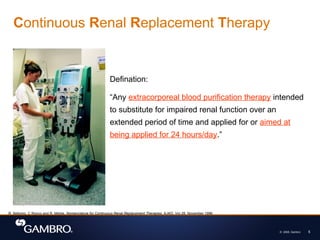
  • #5 Drs. Bellomo, Ronco and Mehta defined Continuous renal replacement therapy (CRRT) as any extracorporeal blood purification therapy intended to substitute for impaired renal function over an extended period of time and applied for or aimed at being applied for 24 hours/day. It is also referred to as slow continuous renal replacement therapy. Treatments are usually performed by a critical care nurse over a 24-hour period, the duration of therapy varying from days to weeks depending on individual patient requirements.
  • #10 ADQI (Acute Dialysis Quality Initiative) is a process initiated by a group of physicians from different part of the world, with the objective to seek consensus and evidence and establish guidelines in the field of acute renal failure. 
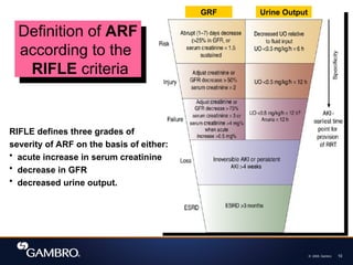
They have proposed the RIFLE classification as a definition of ARF (acute renal failure). RIFLE defines three grades of severity of ARF on the basis of either an acute increase in serum creatinine, decrease in GFR or decreased urine output.
  • #12  AZOTEMIA 
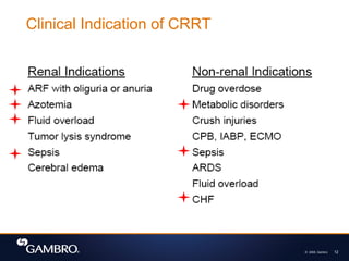
Azotemia is a condition where the patient's blood contains uncommon levels of urea, creatinine, and other compounds rich in nitrogen. Azotemia is also one clinical characteristic of a wider condition known as uremia, which includes other conditions such as acidosis, anemia, hyperkalemia, hypertension, hypocalcemia, etc.
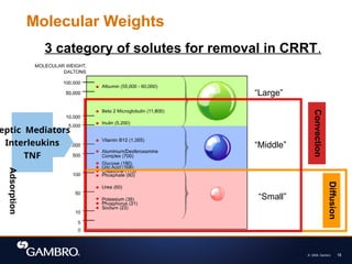
  • #18 The solutes, or molecules, that clinicians target for removal and maintenance during therapy come in different sizes, the weights of which are expressed in daltons. These solutes are classified into small, medium, or large depending on their molecular weight. For example, urea and creatinine, which are molecules usually used as markers for efficiency of dialysis treatment, are considered small. Vit. B12, which is not a molecule targetted for removal but is usually used as a marker for middle molecules, are considered a middle molecule. Septic mediators, interleukins and TNF, fall in this category. Beta-2 microglobulins, a large molecule, has been described as the cause for microinflammatory diseases for chronic dialysis patients, and is usually used to describe the efficiency of a hemofilter membrane. Whereas albumin is a molecule too large to pass through the pores of a hemofilter membrane.
  • #19 There are Option/modality choose for dialysis
  • #21 IHD CCF pt
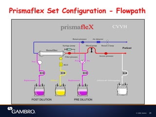
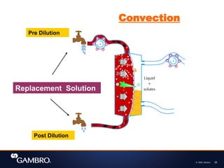
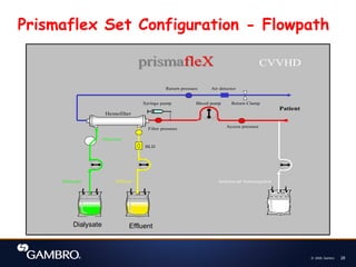
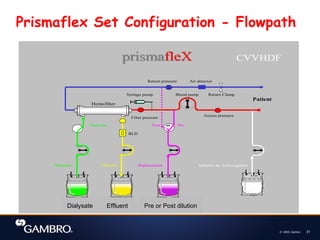
  • #24 From the animation, you see also that replacement fluid can be added at 2 points: 1st is when replacement fluid is added to the blood before it enters the haemofilter. This is known as pre dilution. 
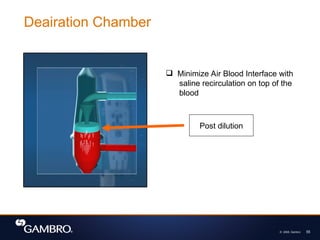
2nd is when replacement fluid is added into blood after it leaves the heamofilter. This is known as post dilution. ( Please do refer to the diagram at the same time you explain) Ask: Why is there a need for Pre and Post Dilution?
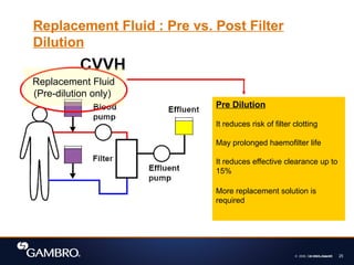
  • #25 In pre dilution, blood is diluted before it enters the haemodfilter. ( please refer to the pink colour box when reading.) Ask: What are the advantages of pre dilution? 1st - It reduces risk of filter clotting 2nd - May prolonged haemofilter life However, the disadvantages are: It reduces effective clearance up to 15%, and hence more replacement solution required to improve clearance
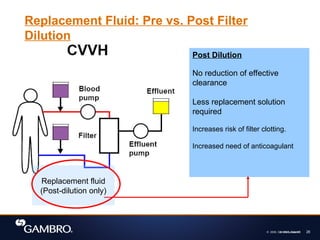
  • #26 In post dilution, replacement fluid is added to patient’s blood after it leave the heamofilter. ( please refer to the pink colour box when reading.) Ask: What are the advantages of post dilution? There is no reduction of effective clearance and hence less replacement solution is required to get the same amount of clearance. However, the disadvantages are: It increases the risk of filter clotting and hence increases need of anticoagulant
  • #29 Read from the yellow box Picture 
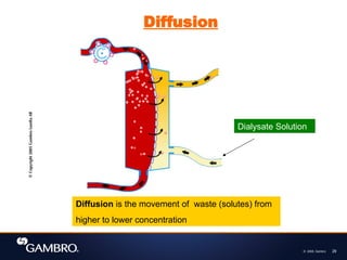
In this haemofilter animation, you can see that Dialysate solution is exposed to the blood across the semi permeable membrane. Important! Dialysate solution is not added to the blood. It is separate from the blood by the semi permeable membrane. The dialysate solution flows in a counter current direction to the blood. This is to maximize the diffusion capability. Go to next slide
  • #32 From the animation, we see that in CVVHDF; both convection and diffusion are used to remove waste.
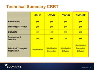
  • #33 This slide summarises the different technique used in CRRT: 
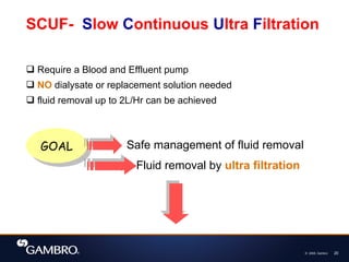
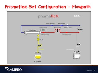
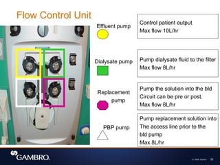
SCUF Slow continuous ultrafiltration. Requires blood and effluent pumps. Pumps used to generate hydrostatic pressure. No dialysate or replacement solutions are required. In this mode, CRRT fluid removal rates up to 2 litres/hr can be achieved. 
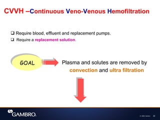
CVVH Continuous veno-venous hemofiltration. Requires use of blood, effluent and replacement pumps. Dialysate solution is not required. Plasma water and solutes are removed by ultrafiltration and convection . 
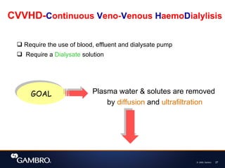
CVVHD Continuous veno-venous hemodialysis. Requires the use of blood, effluent and dialysis pumps. Replacement solution is not required. Plasma water and solutes are removed by ultrafiltration and diffusion . 
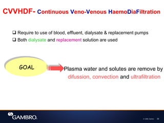
CVVHDF Continuous veno-venous hemodiafiltration. Requires the use of blood, effluent, dialysate and replacement pumps. Both dialysate solution and replacement solution are used. Plasma water and solutes are removed by ultrafiltration convection and diffusion.
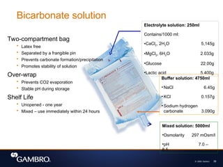
  • #39 As you know, bicarbonate is the most physiologically compatible and therefore is the preferred solution for patients. It comes in a two-compartment plastic bag, which is latex free. The contents of each compartment is separated by a red colored frangible pin. The large compartment contains 4750ml of solution composed of sodium hydrogen carbonate and water. This solution has a pH of 8.3. The small compartment has 250ml of solution which contains electrolytes such as NaCl, variable K+ and Ca+, MgCl, Lactic Acid and water. Separating the carbonate from Ca and Mg prevents carbonate formation and precipitation. In addition, the over-wrap prevents carbonate evaporation and therefore promotes the stability of the solution during storage. Unmixed, the solution has a shelf life of one year. Gambro recommends that the solution is used immediately after mixing the contents of the two compartments, up to 24hours after removing the overwrap. No stability test has been done for other additives to the solutions.
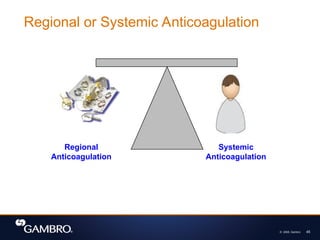
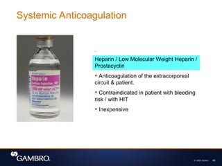
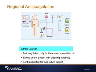
  • #45 The role of anticoagulation during CRRT is to minimize the effects of membrane exposure to blood and maintain the functional integrity of the filter and the patency of the circuit. The ultimate goal is to minimize clotting of the extracorporeal circuit without systemically anticoagulating the patient while minimizing the systemic side effects of anticoagulation. There are two types of anticoagulation strategies often used to obtain this goals, either by systemic or regional anticoagulation. Systemic anticoagulation involves anticoagulating both the extracorporeal circuit and the patient. Regional anticoagulation refers to anticoagulation restricted to the extracorporeal circuit.
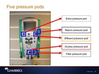
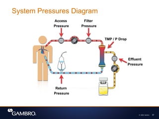
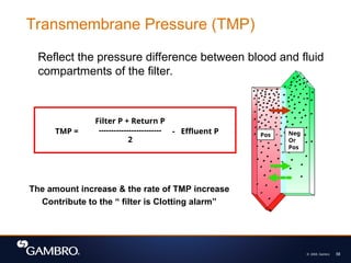
  • #58 TMP or Trans Membrane Pressure is the pressure exerted on the filter membrane, it reflects the pressure difference between the fluid and blood compartment of the filter. Most CRRT Systems automatically calculates the TMP of the membrane with this formula, taking into account the filter pressure (pressure at the blood inlet of the filter), the return pressure and the effluent pressure (pressure at the fluid outlet). An increase in the TMP may signify protein coating on the blood side of the membrane, or clotting of the fibers. The TMP in the filter data is described in mmHg/kPa. A Pascal is a unit of pressure equal to one Newton per square meter. A Newton is the international standard unit of force. A maximum TMP is specified for each hemofilter. The bigger the surface area of the filter, the more room to increase the blood flow before reaching the maximum TMP. If all the alarm systems in a machine fails, and the TMP was allowed to go beyond the maximum limit, what do you think would happen to the membrane? What does a negative TMP mean? (backfiltration, or the filter is much bigger than the programmed fluid removal)
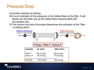
  • #59 Blood pressure drop of a hemofilter is usually indicated in the filter data for CRRT. It is a calculated value using the measured pressure as the blood is entering and leaving the filter, at a certain blood flow rate with the specified UFR in post-dilution mode. The bigger the BP drop, the more susceptible the hemofilter is to clotting with higher UFR. The bigger the surface area of the hemofilter, the lower the BP drop would be, therefore, a bigger filter would allow higher UFR with lower risk of clotting.