1. Reliability of timber columns considering long-term material behaviour
Becker, Peter1
, Rautenstrauch, Karl 2
INTRODUCTION
Former design rules for simply supported timber columns were derived by performing short-term tests using small clear
wood specimens loaded concentrically. This rather traditional approach was not accepted to reflect the developments of
modern timber engineering anymore, so great efforts were undertaken to achieve some kind of improvement in timber
column design in the 80‘s. These efforts mainly concentrated on considering aspects, which were not taken into account
in earlier approaches. Two important works should be mentioned here. Buchanan & al (1985) considered the plasticating
ability of the material under compression. They also realized, that columns are never loaded concentrically, especially
because of knots and material variability. Furthermore it was noticed, that slender columns may fail in tension, and size
effects may affect the tension failure. Blass (1987) continued the research by determining natural distribution of
mechanical and geometrical parameters, to simulate many columns. Characteristic strength values were obtained this way,
which replaced the widely empirical ones in European codes.
Today it is widely accepted, that time-dependent material behaviour additionally influences the load bearing performance
of a column. Many researchers reported about research requirements in this area (i.e. Buchanan & al 1985,
Fridley/Rosowsky 1996, Fromhold/Fridley 1998, Rautenstrauch/Becker 1998). There are different possible effects as a
consequence of long-term behaviour of compressive members:
• The additional lateral deformation of a column because of creep causes an enlarged bending moment according to
theory of second order. This again is followed by additional elastic and creep deformation. The therefore enlarged
edge stresses will result in an earlier failure of the element if the load is raised.
• Duration-of-load (DOL) phenomenons are reported to be closely related to the creep behaviour of timber. It is not
clear though in which way this effect has to be treated separately. Unfortunetely most of the DOL-research
concentrates on the question of time to failure under high levels of loading, but not on a possible influence on
strength under moderate long-term loading.
• Another important point is, that no structural element in use will be exposed to a constant climate. Depending on
service class environmental changes will be of different quantity. Anyway the average moisture content and the
moisture distribution over the cross section will vary and as it is known that moisture dependency is especially large
for compression strength it becomes clear, that there is another aspect to consider.
Creep deflections are mainly caused by permanent load. The proportion of permanent load does not make a big difference
in present European design rules. It is clear though, that the long-term safety will be lower, if dead-load proportion is
high. The object of the related research has to be to develop a design, which produces the same safety margin after long-
term loading independently of load combination and environmental conditions.
In this paper suggestions about including time-dependent effects in column design are discussed. A simulation study,
which is presently prepared by the authors is introduced. First results are presented.
OBSERVATIONS AND EXPERIMENTAL RESULTS
Källsner and Noren (1975) mention a reduction of column loading capacity because of creep. They observe a similar
1
Research Associate, Dept. of Timber and Masonry Engineering, Bauhaus-University Weimar, Germany
2
Professor, Dept. of Timber and Masonry Engineering, Bauhaus-University Weimar, Germany
2. effect for slender and medium slender columns. The influence vanishes if slenderness is low. Humphries and Schniewind
(1982) report about douglas-fir-experiments with slender columns, loaded by 1,67-times the allowable design load by that
time, which refers to 61% of the Eulerload. The specimens (6,35×9,53 mm², L/d=50) were subjected to a relative
humidity, varying in a form of a square wave with a 24-hour period. The researchers soon registered increasing deflection
rates, which led to failure for many of the columns. During the test duration of 14 days 15 of 34 specimens actually failed.
Similar experiments were done by Cheng and Schniewind (1985). Geometrical parameters were identical to the ones of
Hunphries/Schniewind (1982). This time three different load levels (1,4/1,6/1,8×design load) were chosen. The specimens
were again subjected to a variable relative humidity of square wave and sinusoidal form. And again the deformation
curves followed a classical shape. Phases of primary, secondary and tertiary creep were passed through before the
specimens eventually failed. During duration of the experiments, which lasted between 16 (1,8×design load) and 53 days
(1,4×design load) clearly more than half of the specimens of each series failed. The results of Humphries/Schniewind and
Cheng/Schniewind indicate, that the level of security for columns might be much lower than it was thought by
constituting the design formulas for slender columns at that time, if it is safe at all. Critics may argue that the experiments
werde done with small samples, whose performance especially under varying environmental conditions cannot be
compared to the behaviour of structural size timber. Still the loads during experiments were quite conservative,
considering that all specimens were individually loaded after determining modulus of elasticicty and Eulerload, while
allowable stress design still contains an allowance for variability of mechanical parameters of the material in its formulas.
Itani, Griffith and Hoyle (1986) stated, that the use of the simple straight, long-column buckling load formula in
American standard may lead to an unacceptable large error. In their experiments under constant environment they used
100×100 mm² specimens, experimental duration of load was taken up to 2000 hours. 70% of the Eulerload proved to be
too much as permanent action even in constant environment. All specimens failed for slenderness ratios of L/d=35 and
45. Only 12 (L/d=35) respectively 8 (L/d=45) of 30 specimens survived the first 200 hours.
The main purpose of the studies of Humphries/Schniewind and Cheng/Schniewind was the determination of times to
failure for columns strained by large permanent loads. They obtained a wide range of results making a prediction of the
time to failure impossible. They stated, that the initial curvature has big influence on the time to failure though, which was
also observed by Itani & al (1986). The interpretation, that the initial curvature is more critical to the long-term
performance of a compressive member than the time-dependent material behaviour is quite misleading. The time to
failure is not decisive for a structural element, the important thing is, that it will survive at all. And this solely depends on
the time-dependent material behaviour as we will see later.
Some further experiments in variable environment were done by Haertel (1999) with medium slender columns (L/d=29)
of structural size glulam and lumber. His applied axial loads corresponded to the allowable loads according to the German
code DIN 1052. Haertel concluded that time-dependent material behaviour is not considered appropriately for column
design. He obtained lateral deflections exceeding the allowable ones by multiples.
ANALYTICAL STUDIES AND RECOMMENDATIONS
Itani & al (1986) analyzed their experimental results by performing simulation studies. As already mentioned they stated,
that the simple, long-column buckling load formula in American standard might be unsafe for slender columns being
subjected to high permanent loads. For safe design in codes following allowable stress concept they recommend the use
of
1
f
d
e
5,7
74,2/P ab
a
mean,E
a
=
σ−
÷
ø
ö
ç
è
æ
σ⋅
+
σ
(1)
where σa is the applied axial stress, fb the allowable bending stress, d the thickness of the column and e the initial warp in
midheight. PE refers to the Eulerload. It has to be mentioned though, that Itani & al drew their conclusions by 400-hours-
simulation results, which is for long-term interpretations of columns definetely too short.
Buchanan & al (1985) recommend to reduce the E-Modulus because of creep influence while computing the lateral
deflection without quantifying this. In another study Blass (1988) admits, that an increase of permanent load results in
disproportionate reduction of ultimate load. In opposition to Källsner/Noren (1975) he states, that this effect is largest for
3. medium slender columns. He also reports that permanent stress, which is below 30% of compressive strength has a
negligible effect.
Leicester (1986) shows possibilities to compute lateral deflections of beam-columns considering creep. The prove is then
done according to theory of second order by using a proposed failure criterion.
Definition of long-term-stability
Progress was achieved in more recent studies of Becker and Rautenstrauch (1998, 2000).They tried to specify the concept
of long-term stability. It is therefore clear, that the lateral deflection rate has to be of decreasing character. Otherwise the
column will fail sooner or later. So in contrast to the Euler load (short-term stability) the long-term stability load („creep
buckling load“) does not refer to a sudden failure, but to a failure, which will certainly take place sometime in the future.
If the creep buckling load is exactly applied a constant deflection rate will be obtained in the long run. Exceeding the
long-term stability load results in an increasing deflection rate („tertiary creep phase“) which will be followed by rupture.
This is the reason, why the initial curvature is not decisive for survival of the column. If the applied load does not exceed
the creep buckling load an equilibrium state of deformation will be obtained in the long run assuming a creep limit, except
a failure criterion is reached before that. And if the creep buckling load is exceeded failure will occur anyway. That’s why
initial curvature is usually not of importance, if column resistance is the only matter of interest.
Simple formulas
Becker/Rautenstrauch (2000) applied linear viscoelasticity theory to the problem using the following assumptions:
• Creep in timber approaches a creep limit for tension and compression loading. This is already assumed in codes,
where creep factors, which refer to the final creep deformation related to the elastic deformation, are applied. Creep
factors are a useful simpification of time-dependent phenomenons for practical engineers. Recent research indicates,
that the assumption of a creep limit is appropriate for loads in service range for all kinds of climatic conditions.
• Linear viscoelasticity is taken to be valid as material law. It is widely accepted, that linear viscoelasticity theory
reflects the material behaviour in service range in a reasonable way. Stresses above service range do not quite justify
this assumption.
Applying these assumptions, Becker/Rautenstrauch (2000) developed formulas, which allow to estimate the finally
occuring creep and elastic deflection and long-term stability. They have done this for permanent and variable loads, which
may act in axial or perpendicular to axis direction. The lateral load has no influence on creep buckling, so only the
formulas including axial loads are presented here. If a column is subjected to a permanent (PG, creep factor ϕG) and a
variable load (PQ, creep factor ϕQ) the finally occuring creep deflection will become
( )
δ δ
ϕ ϕ ϕ
ϕ ϕ ϕ
ϕ = ⋅
+ − +
− + − + + + +
0
2 1 1
G G Q Q G G G Q E
E G G Q Q G G G Q E
P P P P P P
P P P P P P P
( ) /
( ) ( ) ( ) /
(2)
δ0 denotes the initial stressless predeflection. The variable load was assumed to act in its full size while present, which is
most conservative and therefore on the safe side. The duration of variable load was determined by the size of the creep
factor compared to the dead load creep factor. As already mentioned PE denotes the Euler load, which can be easily
obtained by
2
2
E EAP
λ
π
= (3)
Here λ stands for the slenderness this time defined by the quotient of length and radius of inertia. The maximum elastic
deflection can be determined by considering the creep deflection as an additional predeflection.
( ) ( )QGE
QG
0el
PPP
PP
+−
+
δ+δ=δ ϕ (4)
It is obvious, that creep deflection becomes large if the denominator in expression (2) approaches zero. This is the case, if
4. creep buckling load combination is applied, so a condition for long-term stability is obtained by equating the denominator
with zero. If the expression is modified it looks as follows:
( ) 0PP
1
1
PP
1
P
PP GE
G
Q
QG
G
E
GE >ú
û
ù
ê
ë
é
−
ϕ+
ϕ+
⋅−÷
÷
ø
ö
ç
ç
è
æ
−
ϕ+
− (5)
This is a rather simple condition to check. For more than one variable load analytical solutions like expressions (2) and
(5) become quite complicated. So Becker/Rautenstrauch (2000) employed long-term simulations to develop a long-term
stability conditions, to which more than one variable load may be applied.
( ) ( )
1,3m,1
P
P1
P
P1
m
E
QQ
m
E
GG
=<ú
û
ù
ê
ë
é ⋅ϕ+
+ú
û
ù
ê
ë
é ⋅ϕ+
å (6)
This nonlinear interaction formula fits very well to the 3-dimensional space of long-term stability under one permanent
and two variable loads and is very easy to use. Because of the conservative way variable loads are applied, it can be
considered to be on the safe side.
APPLYING LONG-TERM SIMULATION
Long-term experiments are big time and money consumers. For this reason computer simulation seems to be an
appropriate method to check what is happening with a structural element in the long run. A possibly most realistic
modeling of the material is essential. It has to contain all observed effects, which may influence the long-term
performance. This is tried presently at the Bauhaus-University in Weimar, Germany. Material behaviour contained in the
model is listed in the following.
• Time-dependent moisture distribution over the cross-section, which is obtained by solving Fick’s second law with
finite difference method here, is considered. The diffusion coefficient is assumed to depend on density and moisture
content. The moisture analysis also contains the effect of surface resistance.
• The deformation behaviour of the material in grain direction is splitted into five parts:
- Elastic deformation occurs according to Hooke’s law. The E-modulus is moisture dependent.
- Hygroexpansion is considered. Coefficients are taken strain dependent, causing higher coefficients under
compression and lower ones for tension as observed in former research. This results in the typically cyclic
deformation curve, which characterizes creep under mechano-sorptive conditions.
- Time-dependent deformation in constant environment (viscoelastic deformation) is covered by a rheological model,
consisting of 4 Kelvin-elements serially arranged. Relative viscoelastic creep is assumed to be constant in different
constant environments, which reflects the observations of most researchers.
- Mechano-sorptive creep is modeled by a further Kelvin-element, which parameters depend on level of stress and
hygroexpansion coefficient in longitudinal direction. Time-increments are replaced by moisture change increments.
All mechano-sorptive phenomenons reported in literature are covered this way, also the ability of recovering after
unloading under additional moisture changes.
- Nonlinear irreversible creep is assumed to occur, if a defined stress threshold is exceeded. The stress threshold value
is moisture dependent and becomes lower for increasing moisture contents as reported in literature.
• Moisture dependency of stationary material parameters (elastic and strength properties) is taken into account.
• Length effects are considered by performing an additional simulation study. The results contain deviations of tension
and compression strength depending on load combination and geometrical parameters of a structural element.
• A damage mechanics approach is applied to account for duration of load effects.
5. • As basic material parameters raw density and knot area ratio values are determined by Monte-Carlo simulation.
Density is assumed to be normally distributed, for knot area ratio determination a lognormal distribution is taken.
Regression formulas are used to account for their influence on mechanical properties and diffusion coefficient.
• Mechanical properties (E-modulus and strength for tension and compression) are also determined by Monte Carlo
simulation, considering the influence of basic material properties and the correlations among themselves. Regression
formulas and deviations are taken from former comparable studies (e.g. Blass 1987).
• Stressless predeflections in column midheight are determined by Monte-Carlo method according to a deviation
published in a paper of Ehlbeck and Blass (1987).
In the simulation the midheight cross section of a simply supported column is divided into several nodes. In each time
increment moisture and stress-strain analysis is performed for all nodes. As compatibility condition for the strain at
different nodes the cross section is assumed to remain plane in deformed state, which means the Bernoulli hypothesis is
adopted.
The parameters used for modeling time-dependent behaviour are mainly empirically determined by resimulating creep
tests, which are well documented in former publications. The model performed extremely well in resimulating numerous
experimental results taken from literature. Due to lack of space the complete model and the results of resimulations will
be published in a later paper.
The final object of the study is to receive a deviation of long-term strength, to get an idea about the still existing safety
margin after long-term loading. The following steps are undertaken to find out about this.
• The nominal short-term strength is determined first. This is done by increasing the load simply until a failure
criterion is reached, which is previously defined. The plasticating ability of the material under compression is
considered. For tension a linear-elastic-brittle material law is assumed. The nominal strength is obtained by simply
dividing the axial load of failure through the cross-sectional area.
• The column is long-term loaded then. A duration of 20 years is chosen. Any load and climatic history is possible.
• After long-term loading the load is raised again to determine the nominal strength, which will be lower because of the
already mentioned effects of course. This long-term strength may be applied to compare it with the short-term
strength and to obtain the remaining level of safety.
Many researchers performing long-term experiments complained, that short- and long-term strength properties cannot be
obtained for the same specimen. So one major advantage of simulation over experimental studies is that a specimen can
be destroyed more than once, which is done by computing the short- and long-term strength.
The simulation program will be taken to perform intensive parameter studies. It is planned to vary the proportion of
permanent load, the column slenderness and environmental conditions to find out about their influence to long-term
behaviour of columns. These seem to be the most important parameters having to be included in long-term design.
Although simulation is much faster than experiments it still proves to be time consuming, because the program contains
several iteration loops. This limits the possible number of simulation samples. This is also the reason resulting long-term
deviations of strength cannot be presented yet.
RESULTS
To show that the program is able to resimulate experiments with compressive members under varying environmental
conditions, a typical time-deformation curve of Cheng/Schniewind (1985) is given in figure 1a. The cyclic shape of the
curve indicates the relative humidity changes, with increasing deflection in drying periods and decreasing deflections
under wetting conditions. Resimulation of the experiment results in a curve which is shown in figure 1b. It can be
observed that the program is able to model all possible phases of creep not only for bending element but also for columns.
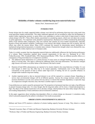
Some further simulations were done with slender columns. A 100×100 mm² cross-section with largest slenderness
allowed according to the German code DIN 1052 (L/d=43,3) was chosen, because the long-term influence is probably
6. even slightly larger for slender columns than for medium slender columns. Relative humidity is assumed to cycle between
74 and 86% in a sinusoidal way over the year. Additional daily cycles of 11 (wet season) and 19%-amplitude (dry season)
are considered, which is assumed to reflect mid-german service-class-3-conditions according to climatic data of the
former German Democratic Republic. The columns were subjected to a permanent load for a duration of 20 years. The
load was chosen as maximum possible load according to Eurocode 5, which is 10,37 kN for the selected column.
Mechanical and geometrical properties were randomly varied for seven specimens leading to results, which can be taken
from figure 2.
Although none of the columns failed during simulation time, an increasing deflection rate can be observed for all columns
after a couple of years, even for the ones which hardly show any deformation. Whether the increasing deflection rates will
all end with column failure cannot be surely stated yet. Even longer simulation durations seem necesary. Although the
time-dependent deflection after 20 years of loading did not exceed the initial predeflection, which has to be taken into
account by applying the proof according to theory of second order following Eurocode 5 (here 13 mm), the initial elastic
deflections in the simulation are exceeded by factors up to 40. Figure 2 also indicates, that the columns with largest initial
predeflection will probably be the first ones to fail, as it was observed by Cheng/Schniewind (1985) and Itani & al (1986).
The duration of load effect is not yet included in these results. It is doubtable though, that there would be any influence by
duration of load phenomenon, which is usually assumed to occur above a certain stress threshold value.
CONCLUSIONS
Column design without considering time-dependent material behaviour is inconsistent. Safety is definetely larger for
columns where low proportions of permanent load are applied. The design might not be safe at all, if the column is
subjected to very high proportions of dead load. This calls for new design procedures, which include time and moisture
effects and result in the same safety margin independently from load combination, slenderness or climatic surroundings.
Application of new design procedures should not result in a more complicated column design though.
Only slender and medium-slender columns may be significantly affected by time-effects. It is absolutely critical, that the
creep buckling load is not exceeded. Otherwise a stable deformation development cannot be guaranteed. Simple formulas
to secure long-term stability are presented by Becker/Rautenstrauch (2000) and taken over in this article. They may be
applied in column design without much effort. The formulas contain creep factors to account for the time-dependent
behaviour. Creep factors were formerly used only for deflection control. Different creep factors for different actions and
service classes in the European code allow to register the influence of each action seperately.
To find out more about long-term column behaviour a simulation study is presently in progress. More results and insight
will be published at a later date.
REFERENCES
Becker, P., Rautenstrauch, K. 2000 – Time-dependent material behaviour applied to timber columns under combined
loading. Part I: Creep deformation. Part II: Creep buckling. Accepted for publication by “Holz als Roh- und Werkstoff”.
Blass, H.J. 1987 - Tragfaehigkeit von Druckstaeben aus Brettschichtholz unter Beruecksichtigung streuender
Einflußgroeßen (Carrying capacity of glulam compressive members with consideration of scattering influential variables).
PhD-Thesis, University of Karlsruhe, Germany.
Blass, H.J. 1988 - Einfluß des Kriechens auf die Tragfaehigkeit von Holzdruckstaeben (Influence of creep on the load-
bearing capacity of timber columns). Holz als Roh- und Werkstoff 46, 405-411.
Buchanan, A.H., Johns, K.C., Madsen, B. 1985 - Column design methods for timber engineering. Proceedings of the CIB-
W18A-meeting, paper 18-2-1, Beit Oren, Israel.
Cheng, J., Schniewind, A.P. 1985 - Creep buckling of small slender wood columns under cyclic environment. Wood and
Fiber Science 17(2), 159-169.
7. Ehlbeck, J., Blass, H.J. 1987 – Imperfektionsannahmen für Holzdruckstaebe (Assumptions for imperfections of timber
columns). Holz als Roh- und Werkstoff 45, 231-235.
Fridley, K.J., Rosowsky, D.V. 1996 - Time effects in the design of wood structures: A review. Structural Engineering
Review 6, 29-36.
Fromhold, K.L.,Fridley, K.J. 1998 - Creep-induces secondary moments in timber beam-columns. Proceedings of the 5th
world conference in timber engineering, Vol.2, Montreux, Switzerland, 356-360.
Haertel, J. 1999 – Experimentelle und theoretische Untersuchungen zum Kriechverhalten hoelzerner Druckstaebe unter
baupraktischen Bedingungen (Experimental and analytical study to the creep behaviour of wooden compressive elements
under practical conditions). PhD-Thesis University of Hannover, Germany.
Humphries, M., Schniewind, A.P. 1982 – Behaviour of wood columns under cyclic relative humidity. Wood Science 15,
44-48.
Itani, R.Y., Griffith, M.C., Hoyle, Jr.R.J. 1986 - The effect of creep on long wood column design and performance. J. of
Structural Eng. 112(5), 1097-1115.
Kallsner, B., Noren, B. 1975 - Strength of a wood column in combined compression and bending with respect to creep.
CIB-W18-paper No 5-9-1, Karlsuhe, Germany.
Leicester, R.H. 1986 - Creep buckling strength of timber beams and columns. Proceedings of the CIB-W18A-meeting,
paper 19-2-1, Florence, Italy.
Rautenstrauch, K., Becker, P. 1998 - Beitrag zur Beruecksichtigung des Kriechens bei Druckstaeben aus Holz
(Contribution to considering creep for timber compressive members). Bautechnik 75, 910-921.
8. FIGURES
a)
b)
Figure 1 Time-deflection curve of axially loaded column obtained by
a) experimental test (Cheng/Schniewind 1985)
b) resimulating test with simulation program
0
5
10
15
20
0 2 4 6 8 10 12 14
Time [days]
Deflection[mm]
9. Figure 2 Simulation results for various columns subjected to long-term loading
0
2
4
6
8
10
0 5 10 15 20
Time [years]
Deflection[mm]