Analysis of Buckling and Post-Buckling Behavior of Plates and Shells
1. 1
Introduction
1.0 Overview
The theory of stability of structures started about 250 years back, with a work
of Euler on buckling of columns in 1759. The classical period of the theory reaches back
as far as 1930-1940. At that time both experiments and theoretical investigations on the
instability of shells revealed shortcomings of the linear theory. Efforts on removing those
discrepancies between the experiments and theoretical predictions for buckling of shells
significantly influenced the development of non linear theories of the analysis of
structures. The beginning of the modern theory of structural stability can be related to the
doctoral thesis by Koiter. The thesis initiated theoretical investigation of post buckling
behavior of structures in the vicinity of critical states. It started with the sensitivity
analysis of structures to initial deformations.The class of problems most frequently
encountered in the field of structural stability in which the loss of stability of one set of
equilibrium states of an idealized or “perfect” elastic structure is associated with
bifurcation into another set of equilibrium states. The first set is referred to as the pre
buckling state and the bifurcated state as the buckled configuration. The bifurcation load
of the perfect structure is commonly called the classical buckling load. This is by no
means the only circumstance under which a structure can become unstable.The classical
analysis of the stability of the pre buckling state of the perfect structure takes the form of
an Eigen value problem for the lowest load level, for which the second variation for the
potential energy is semi definite. The Euler equations associated with this variable
principle is linear and the Eigen mode associated with the critical is termed as the
buckling mode.
1.1 Objective
The way in which buckling occurs depends on how the plate or shell is
loaded and on its geometrical and material properties. The pre buckling process is often
nonlinear if there is a reasonably large percentage of bending energy being stored in the
shell throughout the loading history. Two types of buckling exist: nonlinear collapse and
bifurcation buckling. Nonlinear collapse is predicted by the means of a nonlinear stress
analysis. The stiffness of a structure decreases with increasing load. At the collapse load
the load-deflection curve has zero slopes and, if the load is maintained as the structure
deforms, failure of the structure is almost instantaneous. This type of instability failure is
often called “snap through” a nomenclature derived from the many early tests and
theoretical models of shallow arches and spherical caps under uniformly distributed
loads. Those very nonlinear systems initially deform slowly with increasing load. As the
load approaches the maximum value, the rate of deformation increases until, reaching a
status of neutral equilibrium in which the average curvature is almost zero, the shallow
arches and caps subsequently “snap-through” to a post buckled state which resembles the
structure in an inverted form.The onset of “bifurcation buckling” is predicted by means of
2. 2
an Eigen value analysis. At the buckling load, or bifurcation point on the load-deflection
path, the deformations begin to grow in a new pattern, which is quite different from the
pre buckling pattern. Failure on unbounded growth of this new direction mode occurs if
the post bifurcation load-deflection curve has a negative slope and the applied load is
independent of the deformation amplitude. The post buckled paths for flat and curved
panels are significantly different. Fix panels exhibit a stable symmetric point of
bifurcation.
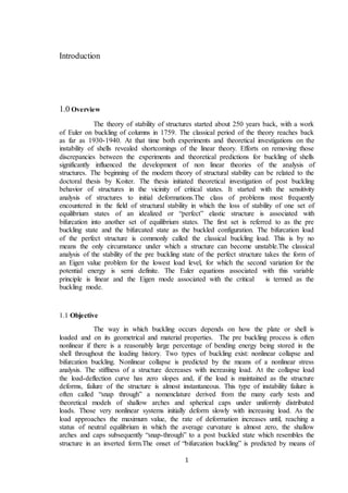
Fig 1.1 Post Buckled deflection curves showing bifurcation and limit points under
uniaxial compression for Flat panel.
It can be observed that the presence of initial geometric imperfection w
destroy the trivial path , and we have now a family of stable equilibrium curves
corresponding to different values of w that round off to the bifurcation of the perfect
system. Curved panels however , exhibit an unstable post buckling response and the load
– carrying capacity of the curved panel is reduced to a value below the bifurcation load
when the response jumps to a new stable equilibrium configuration at limit point.Snap
through and snap back buckling phenomenon pose some of the most difficult problems
in nonlinear structural analysis. The Newton types methods are often used to solve
nonlinear structural stability problems. The usual Newton Raphson method or its
modified version, self correcting or standard incremental method, belongs to this
category. It is necessary to modify the standard forms of these methods if these are
employed to trace the post buckling configurations including snap through and snap back
solution paths. For instance referring to Fig 3, if the displacement w were to be
prescribed , the limit point B could be passed and the load shedding curve BC could be
traced. However, the displacement control method would fail at, or just before, the limit
point F. A great number of procedures have been proposed to overcome these problems.
The most widely used scheme is the arc length method proposed by Riks and Crisfield. It
established the loading parameter as a variable. Since the loading level is treated as a
variable an equation is required in addition to the usual equilibrium equations. This
3. 3
additional equation uses the arc length of the load displacement curve as a controlling
parameter.
Further, flat and curved panels are the most extensively used slender
structural elements in aerospace, spacecraft and other major disciplines. These
components are susceptible to a variety of in-plane as well as out of – plane thermo
mechanical loads. These loading conditions typically occur in a dynamic environment.
Changes in panel vibration characteristics due to the interaction of thermal and
mechanical loading affect panel dynamic response and flutter characteristics. Thus
understanding the effects of buckling, post buckling behavior of shells, plate’s isotropic,
orthotropic and composite plates.
Fig 1.2 Load displacement curves showing snap- through and snap back buckling
In practice, buckling is characterized by a sudden failure of a structural
member subjected to high compressive stress, where the actual compressive stress at the
point of failure is less than the ultimate compressive stresses that the material is capable
of withstanding.
1.3 State of Art
Mathematical analysis of buckling often makes use of an axial load eccentricity that
introduces a secondary bending moment, which is not a part of the primary applied forces
to which the member is subjected. As an applied load is increased on a member, such as
column, it will ultimately become large enough to cause the member to become unstable
4. 4
and is said to have buckled. Further load will cause significant and somewhat
unpredictable deformations, possibly leading to complete loss of the member's load-
carrying capacity. If the deformations that follow buckling are not catastrophic the
member will continue to carry the load that caused it to buckle. If the buckled member is
part of a larger assemblage of components such as a building, any load applied to the
structure beyond that which caused the member to buckle will be redistributed within the
structure.Numerical solutions of partial differential equations are traditionally
accomplished by some variant of the methods of finite difference and finite elements.
These methods approximate the partial derivatives of a function at a grid point using only
a limited number of function values in the vicinity of the grid point. The accuracy and
stability of these methods depend on the sizes of the grid spacings.
In many practical applications the numerical solutions of the governing
differential equations are required at only a few points in the physical domain.
Frequently, for reasonable accuracy, conventional finite difference and finite element
methods require the use of a large number of grid points. Therefore, even though
solutions at only a few specified points may be desired, numerical solutions must be
produced at all grid points.In many cases the computational effort can be alleviated by
using the method of differential Quadrature , introduced by Bellman which approximates
the partial space derivatives of a function by means of a polynomial expressed as a
weighted linear sum of the function values at the grid points. Obviously, this method is
subject to the limitations of the polynomial fit. As the order of the polynomial increases,
the accuracy of the representation increases up to the point where oscillations introduce
undesirable behavior. However, the limitation on the number of grid points that may be
used can be circumvented by standard numerical interpolation techniques for obtaining
intermediate point solutions which are generally adequate.
5. 5
A Review of Literature
2.1 Introduction
The buckling problem of a thin rectangular elastic plate subjected to in-plane
compressive and/or shear loading is important in the aircraft, civil and shipbuilding
industries.There have been very few previous solutions for the case of non-linearly
distributed edge loadings. Perhaps this scarcity is due to the additional complexity of
having to first solve the problem in plane-stress elasticity for obtaining the internal pre-
stress distribution, and then the buckling problem . The first work in this area was
perhaps due to van der Neut, which considered a uni-axial compressive loading with a
half sine distribution. Later, Benoy considered a uni-axial compressive loading with a
parabolic distribution and obtained an energy solution. It was pointed out by Bert and
Devarakonda that the works of van der Neut and Benoy both suffered from some
serious deficiencies, such as: the distribution of the x-direction in-plane normal stress was
assumed to depend only on the y coordinate; and the contributions of the y direction in-
plane normal stress and the in-plane shear stress have been ignored. Actually there is a
stress-diffusion phenomenon that causes all three in-plane stress distributions to vary
with x as well as y.
Recently, Bert and Devarakonda have removed these deficiencies and thus
yielded more accurate buckling load for the case of thin rectangular plate with all
boundaries simply supported under sinusoidal edge loadings. A year later, Devarakonda
and Bert extended their analysis to include three other combinations of boundary
conditions. The Galerkin method is employed in obtaining the buckling load. However, a
careful study shows that their analytical results are still not sufficiently accurate due to
the difficulty of satisfying all boundary conditions exactly in solving the problem in
plane-stress elasticity. Perhaps due to the complicated mathematical structure of the
problem, obtaining closed-form solutions under various combinations of boundary
conditions is generally difficult. Therefore, the problem remains unsolved satisfactorily.
The differential Quadrature (DQ) method, introduced by Bellman and Casti , is an
efficient numerical technique for the solution of initial and boundary value problems.
Since Bert et al. first used the method to solve problems in structural mechanics, the
method has been well developed and applied successfully to a variety of problems. Shu
provided the explicit formulation and recurrence relationships to compute the weighting
coefficients thus improved their accuracy, especially, when the number of grid points is
large. Chen et al. presented a special matrix product technique, which simplified the
computer implementation and improved the efficiency of the DQ method, especially, in
solving non-linear problems. Chen and Tanaka extended the applications of DQ method
to initial-value problems , where DQ method was used to approximate temporal
derivatives. It was found, however, that solutions by the DQ method were very sensitive
to grid spacing when it was used for solving buckling problems of anisotropic rectangular
plates even under uniform edge loadings . Thus, non-uniform grid spacing and new ways
to apply the boundary conditions have been proposed . If recurrence relationships are
used to compute the weighting coefficients, the discretized governing equation at the
interior points immediately adjacent to the boundary should be replaced by the
6. 6
discretized boundary condition to achieve the best accuracy. Accurate buckling loads of
anisotropic plates were obtained by the DQ method .
2.2 Buckling Analyses of Plates:
In practice, buckling is characterized by a sudden failure of a structural
member subjected to high compressive stress, where the actual compressive stress at the
point of failure is less than the ultimate compressive stresses that the material is capable
of withstanding. Mathematical analysis of buckling often makes use of an axial load
eccentricity that introduces a secondary bending moment, which is not a part of the
primary applied forces to which the member is subjected. As an applied load is increased
on a member, such as column, it will ultimately become large enough to cause the
member to become unstable and is said to have buckled. Further load will cause
significant and somewhat unpredictable deformations, possibly leading to complete loss
of the member's load-carrying capacity. If the deformations that follow buckling are not
catastrophic the member will continue to carry the load that caused it to buckle. If the
buckled member is part of a larger assemblage of components such as a building, any
load applied to the structure beyond that which caused the member to buckle will be
redistributed within the structure.Numerical solutions of partial differential equations are
traditionally accomplished by some variant of the methods of finite difference and finite
elements. These methods approximate the partial derivatives of a function at a grid point
using only a limited number of function values in the vicinity of the grid point. The
accuracy and stability of these methods depend on the sizes of the grid spacings.
In many practical applications the numerical solutions of the governing
differential equations are required at only a few points in the physical domain.
Frequently, for reasonable accuracy, conventional finite difference and finite element
methods require the use of a large number of grid points. Therefore, even though
solutions at only a few specified points may be desired, numerical solutions must be
produced at all grid points.In many cases the computational effort can be alleviated by
using the method of differential Quadrature , introduced by Bellman which approximates
the partial space derivatives of a function by means of a polynomial expressed as a
weighted linear sum of the function values at the grid points. Obviously, this method is
subject to the limitations of the polynomial fit. As the order of the polynomial increases,
the accuracy of the representation increases up to the point where oscillations introduce
undesirable behavior. However, the limitation on the number of grid points that may be
used can be circumvented by standard numerical interpolation techniques for obtaining
intermediate point solutions which are generally adequate.
It was experienced earlier by the first author of the present article; however,
that direct applying DQ method to solve second order partial differential equations in
terms of displacements, a problem in plane-stress elasticity, for obtaining the in-plane
7. 7
stress distributions under either pure stress boundary conditions or mixed boundary
conditions was not quite successful. Therefore, instead of solving the second order partial
differential equations in terms of displacements, the fourth order partial differential
equation in terms of Airy stress functions and the compatibility equation is solved by the
DQ method and accurate stress distributions can be obtained for cases of uniform and
non-uniform distributed in-plane loadings with all stress boundary conditions.
In view of the fact that very few previous solutions are available for the case of non-
linearly distributed edge loadings and that the DQ method and its equivalents have only
been successfully used to obtain buckling loads for the cases of uniform or linearly
distributed loadings; therefore, the DQ method is extended to analyze buckling problems
of thin rectangular plates subjected to cosine distributed in-plane loadings. Formulations
and procedures are worked out in detail. The buckling loads for rectangular plates with
nine combinations of boundary conditions and various aspect ratios are obtained and
compared with available data or results by finite element method. It is found that fast
convergence rate can be achieved by the DQ method with non-uniform grids and very
accurate results can be obtained. It is also found that the DQ results, verified by the finite
element method with NASTRAN, are comparable to the newly reported analytical
solutions by Bert and Devarakonda . Some conclusions are drawn based on the results
reported herein.The buckling of thin rectangular plates with cosine-distribute along two
opposite plate edges is considerably complicated, since it requires that first the plane
elasticity problem be solved to obtain the distribution of in-plane stresses, and then the
buckling problem is solved. Bertand Devarakonda give the first known analytical
solutions for thin rectangular plates with four boundary conditions. It is found that,
however, their analytical solutions seem still not accurate enough, since all in-plane stress
boundary conditions are not met exactly. Thus the problem is re-solved numerically by
employing the new version of the DQ method. Detailed formulations and solution
procedures are given. It is found that the convergence rate of DQ method with non-
uniform grids is excellent. Buckling loads of rectangular plates with nine combinations of
boundary conditions are obtained. Comparisons are made with existing analytical and/or
finite element data. It is shown that the DQ method can yield very accurate results for all
cases considered. Most data are believed novel and could be used for testing other newly
developing numerical methods or even analytical numerical data. It should be pointed out
that although the DQ method has been proved to be simple, accurate with small
computational effort for problem studied thus far, but the method is not as versatile as the
popular finite element and finite difference method and can only be used for some
problems with regular domain, continuous loadings and geometry. Further studies to
improve the method and extend its application ranges are necessary, for example,
efficient ways for solving problems with irregular domains, or/and with dis-continuous
loading, materials and geometry.
8. 8
2.3 Vibration Of Plates:
Plates belong to basic structural elements in civil and mechanical engineering
and, therefore, they are often subjects of static and dynamic research. Many numerical
methods have been used in dynamical analysis of plates with various boundary
conditions. The obtained results have been used in real structures or as the comparison of
accuracy and convergence for applied methods. The conventional differential quadrature
method has also been applied to the vibration analysis of plates. The results show that the
convergence rate of the PDQM is very high. Very accurate results can be obtained
applying a grid with points densely concentrated near boundaries. The use of an arbitrary
grid, for example a uniform one, makes the results inaccurate or the method not
convergent. This drawback can be overcome by using SDQM.. Since the results and
conclusions coming from application of the DQM.to vibration analysis of plates are
common and well know, the SDQM has been applied to check its versatility in using
various grid point distributions. The dimensionless governing equation for free vibration
of the plate is as follows:
In the above equation W denotes dimensionless mode shape function, X = x/a and Y = y/b
are dimensionless coordinates, a and b are leng- ths of the plate edges, _ = a/b is the
aspect ratio and is the dimensionless frequency. Its relation with the dimensional circular
frequency is following:
where _ is the density of the plate material and D = Eh3/[12(1 − µ)] is the flexural
rigidity.
9. 9
Objective and Scope
In science buckling is a mathematical instability, leading to a failure mode.
Theoretically, buckling is caused by a bifurcation in the solution to the equations of static
equilibrium. At a certain stage under an increasing load, further load is able to be
sustained in one of two states of equilibrium: an undeformed state or a laterally-deformed
state.
Plates and shells with their inherent directional properties are being used as
structural materials in most of the fields now. They are finding applications as load
carrying member for various modern vehicles. In such conditions the analysis of stability
and vibration characteristics of plates and shell become of utmost importance.Thus the
theory of stability of structures is an important part of structural mechanics. In current
scenario the theory of structural stability can be related to theoretical investigations of
post buckling behavior of structures in vicinity of critical states. To analyze the plates
Differential Quadrature method is used. The differential Quadrature (DQ) method is a
numerical technique for solving differential equations. It was first developed by the late
Richard Bellman and his associates in the early 1970s. The DQ method, akin to the
conventional integral Quadrature method, approximates the derivative of a function at
any location by a linear summation of all the functional values along a mesh line. The
key procedure in the DQ application lies in the determination of the weighting
coefficients. Initially, Bellman and his associates proposed two methods to compute the
weighting coefficients for the first order derivative. The first method is based on an ill-
conditioned algebraic equation system. The second method uses a simple algebraic
formulation, but the coordinates of the grid points are fixed by the roots of the shifted
Legendre polynomial. At some boundary value problems, DQM performance is highly
dependent on the boundary conditions and sampling grid points. The overall sensitivity of
the model especially depends on the location and number sampling grid points. However,
the boundary conditions can be easily implemented to DQ system. The boundary
conditions, which are usually Dirichlet, Neuman and/or mixed type function, do not
create any difficulty in this implementation process, Civalek implies that the
determination of the effective choice for any problem reduces the analysis time. For
instance, previous studies show that, in the problems that have linear equations and
homogeneous boundary conditions, selecting equal intervals are adequate for solution. In
vibration problems, the choice of grid points through the Chebyshev-Gauss-Lobatto
method is more reasonable.The buckling of thin rectangular plates with non-linearly
distributed compressive loading on two opposite sides received lesser attention than the
one with uniformly or linearly distributed loads. The problem is considerably more
complicated since it requires that first the plane elasticity problem be solved to obtain the
distribution of in-plane stresses, and then the buckling problem is solved. Since it is
difficult to obtain the analytical solutions accurately with a few series terms for the in-
plane problem, very few analytical solutions have been available in the literature thus far.
Therefore, the problem is analyzed by using differential Quadrature (DQ) method.
Detailed formulations and solution procedures are given in the project. Two combinations
of boundary conditions and various aspect ratios are considered. Comparisons are made
with finite element data with very fine meshes and existing analytical or numerical
solutions. It is found that fast convergent rate can be achieved by the DQ method with
non-uniform grids.
10. 10
The advantages of DQ are numerous over Finite element analysis. It is found
that the present method gives good accuracy and is computationally efficient. Exact
solutions can be obtained by the DQ method if analytical solutions are polynomials and
the method is insensitive to the spacing of grid points for the cases considered.
In mathematics, the finite element method (FEM) is a numerical technique for finding
approximate solutions to boundary for differential equations. It uses variation
methods (the calculus of variations) to minimize an error function and produce a stable
solution. Analogous to the idea that connecting many tiny straight lines can approximate
a larger circle, FEM encompasses all the methods for connecting many simple element
equations over many small sub domains, named finite elements, to approximate a more
complex equation over a larger domain. It has been observed that the FEM is inaccurate
for few cases and needs a usable theoretical background for its correct application. It is
time taking and reorganization of design process is required for the results to be accurate.
Thus the ultimate scope of this project is to study the non linear free vibration
of orthotropic plates with finite deformations and the effect of higher order transverse
shear deformation is studied by using DQM. Good convergence is presented even when
only a small number of grid points are used. A wide variety of cases are performed to
examine the non linear free vibration characteristics of orthotropic plates. The difference
between the non linear frequency and linear vibration frequency increases with increase
in the dimensionless amplitude and the thickness-to-length ratio. It can be seen that the
present DQM is accurate and efficient for solving complex nonlinear problems.
11. 11
Mathematical Formulation
4.1 Differential Quadrature Method:
Basically, the method of differential Quadrature expresses a partial derivative
of a function with respect to a coordinate direction as a weighted linear sum of all the
function values at all mesh points along that direction.
Thus, in general, the linear transformation for a derivative of order m can be
expressed by:
where xi : i = 1, 2,..., N, are the sample points obtained by breaking the x variable into N
discrete values , f(xi) are the function values at these points, and wij are the weights
attached to these function values. Note that the order of the Quadrature must be greater
than the order of the partial derivative; i.e.
N > m.
To determine the weighting coefficients wij the function f(x) is represented by an
appropriate analytical function, such as a polynomial:
and its m th derivative:
On substituting the above values the equations become:
This set has a unique solution for the weighting coefficients Wij because the matrix
elements compose a Vandermonde matrix whose inverse can be obtained analytically as
shown by Hamming . Typical weighting coefficient matrices for the first and second
order derivatives are presented in last.
For multi-dimensional problems considering any pair of the independent variables, such
as x and y, the first order derivative approximation formula given above equation can be
expressed in closed form by the following linear transformations for the partial
derivatives with respect to x and y:
12. 12
where F = f[(xi, yj, zk, t)] is the function matrix consisting of the function values at the
grid points represented by i = 1, 2 ,..., NX, j = 1, 2 ,..., NY, and k = 1, 2 ,..., N’. where p =
q = 1, 2 ,., is the weighting coefficient matrix whose elements are attached to those
function values in the x and y directions, respectively, and t is the time variable.
The approximation formulae for higher order partial derivatives are obtained by iterating
the linear transformations given by above equations. Thus, for example, the second order
partial derivatives are:
Obviously, above Eqs require more computation than that of above equations. To
economize on the computing effort for the evaluation of the second order partial
derivatives remains unchanged for the cross partial derivative because differential
Quadrature expresses the partial derivatives in terms of the function values in one
direction only and
can be replaced by the following linear transformations which are
extensions of a method inferred by Mingle :
Extending this approach, third and higher order partials-in one coordinate direction only-
can be approximated by linear transformations in a similar manner. For convenience, the
approximation formulae for the first and second order partial derivatives, which are
adequate for handling a wide variety of problems, are tabulated .
13. 13
Numerical Results & Discussion:
To verify the analytical formulation presented by other method isotropic
rectangular plates are considered Plates of different types of boundary conditions are
selected as test samples to demonstrate the applicability and accuracy of DQ method. The
governing differential equations for free vibration, bending and buckling of plates and
columns are presented. The present formulations are based on classical small deflection
and thin plate theory. Then, the DQ method is applied to theses differential equations.
The results are obtained for each case using various numbers of grid points.
Subsequently, several test samples for different support conditions are selected to
demonstrate the convergence properties, accuracy and the simplicity in numerical
implementation of DQ procedures. The numerical results for various example plate and
column problems are tabulated and a comparison of the present results with exact or other
numerical values available in the literature, when possible is made.
5.1 Buckling Analysis of Thin & Isotripic Plate:
The governing differential equation of buckling of a thin Rectangular plate is
given by:
Where E is the modulus of elasticity of the plate material, h is the uniform plate
thickness. Above equation can be written by applying the DQM as:
5.2 Differential Equation for Rectangular plates:
The governing differential equation of buckling of a thin rectangular plate is
given by:
where u is the transverse displacement of the mid surface of the plate. may be written in
the following non-dimensional form:
14. 14
where U is the dimensionless mode function of the deflection, X ¼ x=a, Y ¼ y=b are the
dimensionless coordinates, a and b are the dimensions of the plate parallel to x-axis and
y-axis, k ¼ a=b is ratio of the plate edge length or aspect ratio, and Hx is the uniaxial
compression load. D denotes the flexural rigidity of plates and it is given as D ¼
Eh3=12ð1 _ m2Þ, m is the ratio, E is the modulus of elasticity of the plate material, h is
the uniform plate thickness can be given by applying the DQM as:
where Nx and Ny are the number of grid points along the x- and y-directions,
respectively, as and Dik, Dik, Bik, Bjm represent the weighting coefficients ofthe fourth-
and second-order derivatives along x-and y-directions for the differential Quadrature
approximation is a fourth-order partial differential equation, so we have to write two
boundary conditions
at each edge for the stability analysis of plates.
5.3 Boundary conditions for rectangular plates:
5,3,1 Four edges clamped (C–C–C–C). The boundary conditions for a plate clamped
on all four edges are that the displacement and rotation must be zero on the edge.
Applying the differential Quadrature to these boundary conditions:
15. 15
5.3.2 Four edges simply supported (S–S–S–S):Displacement and moment must be zero
on the edge.
Applying the differential Quadrature to these boundary conditions:
and
at the corner. The other possible support conditions can be obtained similar to the
equations summarizes the numerical results of non-dimensionalized buckling loads by
DQ and HDQ for cases of square plates with four different support conditions. As can be
seen, the HDQ results compare very well with the analytical solutions from references
for only 9 _ 9 grid points. It is observed that by increasing the number of grid points
within the range 5 Nx ¼ Ny 9, the HDQ results monotonically approach the
corresponding exact results. Type-II grid points are used as the grid points. It should be
noted that the HDQ solution converges at a smaller grid size as compared to the DQ
solution. Buckling loads obtained for square plates are presented in together with the
exact solutions and finite element solutions obtained by using four different grid
numbers in each direction are presented in the table. The results obtained from the finite
element method are indicated by FEM. Reasonably accurate results can be achieved by
using only 7 _ 7 grid points for HDQ. The variation of the error with the number of grid
points was for the HDQ and FE methods. The percentage of error had been reduced in
16. 16
parallel to the increase of the grid points. In this figure, S–S–S–S and C–C–C–C supports
are taken as boundary conditions.
The best solution is obtained for 9 _ 9 grid sizes by using the HDQ method. However,
reasonably accurate results can be achieved by using 13 _ 13 grid points for the FEM in
this case. From the table, the convergence of the HDQ method is seen to be very good. It
is also
shown in this table that HDQ method produces better convergent solutions than the FEM
when a similar number of grid points are used.
5.4 Results:
All edges Simply Supported:
Spline Based Differential Quadrature Method:
N=9 N=11 N=13 N=15
S-S-S-S 4.0042 3.999 4.000 4.000
Table 5.1
Al Edges Clamped:
Spline Based Differential Quadrature Method:
N=9 N=11 N=13 N=15
S-S-S-S 12.0343 13.2616 14.4717 14.4717
Table 5.2
19. 19
6.0 Conclusion:
In practice, buckling is characterized by a sudden failure of a structural
member subjected to high compressive stress, where the actual compressive stress at the
point of failure is less than the ultimate compressive stresses that the material is capable
of withstanding. Mathematical analysis of buckling often makes use of an axial load
eccentricity that introduces a secondary bending moment, which is not a part of the
primary applied forces to which the member is subjected. As an applied load is increased
on a member, such as column, it will ultimately become large enough to cause the
member to become unstable and is said to have buckled. Further load will cause
significant and somewhat unpredictable deformations, possibly leading to complete loss
of the member's load-carrying capacity. If the deformations that follow buckling are not
catastrophic the member will continue to carry the load that caused it to buckle. If the
buckled member is part of a larger assemblage of components such as a building, any
load applied to the structure beyond that which caused the member to buckle will be
redistributed within the structure. Numerical solutions of partial differential equations are
traditionally accomplished by some variant of the methods of finite difference and finite
elements. These methods approximate the partial derivatives of a function at a grid point
using only a limited number of function values in the vicinity of the grid point. The
accuracy and stability of these methods depend on the sizes of the grid spacings.
In many practical applications the numerical solutions of the governing
differential equations are required at only a few points in the physical domain.
Frequently, for reasonable accuracy, conventional finite difference and finite element
methods require the use of a large number of grid points. Therefore, even though
solutions at only a few specified points may be desired, numerical solutions must be
produced at all grid points. In many cases the computational effort can be alleviated by
using the method of differential Quadrature , introduced by Bellman which approximates
the partial space derivatives of a function by means of a polynomial expressed as a
weighted linear sum of the function values at the grid points. Obviously, this method is
subject to the limitations of the polynomial fit. As the order of the polynomial increases,
the accuracy of the representation increases up to the point where oscillations introduce
undesirable behavior. However, the limitation on the number of grid points that may be
used can be circumvented by standard numerical interpolation techniques for obtaining
intermediate point solutions which are generally adequate.
Plates and shells with their inherent directional properties are being used as structural
materials in most of the fields now. They are finding applications as load carrying
member for various modern vehicles. In such conditions the analysis of stability and
vibration characteristics of plates and shell become of utmost importance.Thus the theory
of stability of structures is an important part of structural mechanics. In current scenario
the theory of structural stability can be related to theoretical investigations of post
buckling behavior of structures in vicinity of critical states. To analyze the plates
Differential Quadrature method is used. The differential Quadrature (DQ) method is a
numerical technique for solving differential equations. Plates belong to basic structural
elements in civil and mechanical engineering and, therefore, they are often subjects of
static and dynamic research. Many numerical methods have been used in dynamical
20. 20
analysis of plates with various boundary conditions. The obtained results have been used
in real structures or as the comparison of accuracy and convergence for applied methods.
The advantages of DQ are numerous over Finite element analysis. It is found that the
present method gives good accuracy and is computationally efficient. Exact solutions can
be obtained by the DQ method if analytical solutions are polynomials and the method is
insensitive to the spacing of grid points for the cases considered. In mathematics,
the finite element method (FEM) is a numerical technique for finding approximate
solutions to boundary for differential equations. It uses variation methods (the calculus
of variations) to minimize an error function and produce a stable solution. Thus the
ultimate scope of this project is to study the non linear free vibration of orthotropic plates
with finite deformations and the effect of higher order transverse shear deformation is
studied by using DQM. Good convergence is presented even when only a small number
of grid points are used. A wide variety of cases are performed to examine the non linear
free vibration characteristics of orthotropic plates. The difference between the non linear
frequency and linear vibration frequency increases with increase in the dimensionless
amplitude and the thickness-to-length ratio. It can be seen that the present DQM is
accurate and efficient for solving complex nonlinear problems. Finite element method is
still an effective way especially in systems with complex geometry and load conditions or
applications with non-linear behavior and has many successful applications.
21. 21
References:
1. Bert Cw, Wang,X And Striz,A Z, Convergence Of The Dq Method In The
Analyses Of Anisotropic Plate, Journal Of Sound And Vibration
2. Krowiak Artur , Methods Based On The Differential Quadrature In Vibration
Analysis Of Plates, Journal Of Theoretical And Applied Mechanics
3. Xinwei Wang, Lifei Gan, Yihui Zhang, Buckling Analysis Of A Laminate Plate,
Engineering Structures Application Of Differential Quadrature (DQ) And
Harmonic Differential Quadrature (HDQ) For Buckling Analysis Of Thin
Isotropic Plates And Elastic Columns
4. Artur Krowiak, Journal Of Theorotical And Applied Mechanics , Methods Based
On The Differential Quadrature In Vibration Analysis Of Plates
5. E. Kormaníková, I. Mamuzic, Buckling Analyses Of Laminated Plate
6. O¨Mer Civalek , Dokuz Eylu¨ L Xinwei Wang , Lifei Gan, Yihui Zhang
Advances In Engineering Software Differential Quadrature Analysis Of The
Buckling Of Thin Rectangular Plates With Cosine-Distributed Compressive
Loads On Two Opposite Sides
7. Faruk Civan And C. M. Sliepcevich , Journal Of Mathematical Analysis And
Applications, Differential Quadrature For Multidimentional Problem