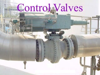
Control Valves
Control Valve
● Control Valve plays a very important part in
industries.
● It controls and distributes pressure, flow,
level, temperature etc.
● Control valve may be considered the
MUSCLE of automatic control.
Types of Valves
● Gate Valve
● Globe Valve
● Plug Valve
● Butterfly Valve
● Diaphragm Valve
Major Parts of a control Valve
● A control valve consists of two major
sub-assemblies.
– A valve body sub-assembly
– An actuator.
● The valve body sub-assembly is the portion
that actually controls the passing fluid.
● It consists:
– Housing
– Internal trim
– Bonnet
Types of Valve Bodies
● Globe Styles
– The most common control valve body style is
in the form of a globe.
– Such a control valve body can be either single
or double-seated.
– Single-seated valves, are usually employed
when tight shut-off is required.
– Tight shut-off in this case usually means that
the maximum expected leakage is less than
0.01% of the maximum valve CV
Single Seated Valves
● Single-seated valves usually have a top
guided construction.
● It also allows a somewhat higher flow
capacity than top and bottom guided valves
for a given orifice size.
Double-seated value
● A double-seated value, is generally top and
bottom guided.
● Leakage figure approaches 0.5% of the rated
CV.
● It is nearly impossible to close the two ports
simultaneously
● Advantage of double-seated construction
lies in the reduction of required actuator
forces.
Angle Valves
● These Valves are single-seated.
● Used for high pressure drop service.
● Minimum Space required.
Cage Valves
● So-called "top entry" or cage valves have
the advantage of easy trim removal.
● Typical top entry valve with unbalanced,
single-seated trim.
● The inner valve parts, often referred to as
"quick change trim," can easily be removed
after removing the bonnet, because of the
absence of internal threads.
Rotary Types of Control Valves
● Advantages
– Low weight
– Simple design
– High relative CV
– More reliable
– Friction-free packing
– Low initial cost.
Rotary Types of Control Valves
● Disadvantage
– Generally not suitable below 1 to 2 inches.
– Operating shaft must be designed to support a
fairly heavy side-thrust.
– Leakage problem.
Butterfly Valves
● The most common type of rotary valve
used for control is the butterfly valve.
● The typical application range is in sizes
from 2 inches through 36 inches or larger,
for low or moderate pressures.
● Leakage 0.5% of rated CV.
Valve Bonnets
● The valve bonnet or top closure is the
removable upper portion of the valve body
sub-assembly and is normally connected to
the body by high strength bolting.
● It is a pressure-carrying part and is,
therefore, subject to the same design
requirements as the valve housing.
● Removal of the valve bonnet generally
provides access to the valve trim.
Valve Bonnets
● Some low-pressure valves, particularly in
sizes below 2 inches, have a threaded
bonnet connection which is more
economical than a flanged joint.
● The upper portion of the bonnet contains
the valve packing.
Valve Body
Bonnet
Valve Body
Valve Body
Packing Box Assembly
● The purpose of the packing box assembly is
to contain an elastic means for preventing
the leakage of a process fluid.
● Suitable adjustments should be provided for
varying the compression of the packing
material against the surface of the stem.
● The ideal packing material should be elastic
and easily de formable.
Packing Box Assembly
● In addition, the packing should be as
chemically inert as possible
● Should be able to withstand high pressures
and high temperatures.
● Selection must be made from a variety of
materials to suit the specific service
conditions.
Packing Box Assembly
● The assembly consists of a:-
– Packing flange
– Packing follower (Bush)
– Lantern ring
– A number of equally spaced packing rings.
– The lantern ring provides a space for the
insertion of lubricating grease though an
isolating valve.
Packing Material
● Teflon (PTFE)
● Graphite
● Grafoil
● Asbestos (Now a days it is not being used)
● Teflon Cord
● Graphite cord
Packing Material
● To make rings
● Special Tool or
● With the help of a Electrician knife
● How to cut and paste the rings
Inert Gas as a Packing
● Another approach is to pressurize the area
between the two packing with inert gas at a
pressure level, slightly higher than the fluid
pressure inside the valve.
● In this case, the inert gas might leak into the
valve, but no fluid is allowed to leak by the
stem.
● This packing arrangement is more reliable.
● Very Expensive
Teflon
● The most popular valve packing material is
Teflon.
● Because of its excellent chemical inertness
and its good lubricating properties.
● Teflon can be used in solid-molded or
turned form (rings).
● Solid rings should be spring-loaded to
provide a minimum initial pressure against
the stem.
● It can be used below 250°C.
Braided Asbestos
● Braided asbestos is still a popular packing
material (even prohibited to use).
● It can be made as split rings.
● Which can be wrapped around the valve
stem.
● This type of packing usually used with mica
or graphite, particularly in high temperature
service.
Grafoil
● A recent addition to the list of available
packing materials is Grafoil.
● Grafoil is an all-graphite product that is
flexible and has direction-dependent
properties.
● It is essentially, chemically inert, except
when strong oxidizers are handled.
Valve Trim
● Main Items:
– Plug
– Seat Ring
– Stem
– Cage
– Guide Bushing
– Stuffing Box
Plug
● Types
● Types depends upon flow characteristic:
– Quick Opening
– Linear
– Parabolic or Equal Percentage
Plug / Seat
● Direct Action Single Seated
● Reverse Action Single Seated
● Direct Action Double-Seated
● Reverse Action Double-Seated
Plug
● Contoured Plug
– Top Guided
– Shape of the plug
• Flat Quick Opening
• A bit Conical Linear
• Tapered but not conical Equal Percentage
Plug Linear
Plug Equal Percentage
Plug Quick Opening
Different Shapes of Plugs
Characteristics of Different Plugs
● Valve Opening 30 %
– Quick Opening CV 62
– Linear CV 30
– Equal % CV 8
– V-Port CV 6
Characteristics of Different Plugs
● Valve Opening 70 %
– Quick Opening CV 90
– Linear CV 70
– Equal % CV 33
– V-Port CV 30
Characteristics of Different Plugs
● Valve Opening 100 %
– Quick Opening CV 100
– Linear CV 100
– Equal % CV 100
– V-Port CV 100
Valve Body
Plug & Cage
Complete Control Valve
● Actuator
● Diaphragm
● Spring
● Yoke
● Indicator
● Coupling Assembly
Complete Control Valve
● Stem
● Bush
● Check Nut of yoke
● Packing Box
● Bonnet
● Body
Complete Control Valve
● Plug
● Seat Ring
● Cage
● Gaskets
● Bottom Guide
Plug
● Types
– Contoured Plug
• Single Port
• Double Port
• Different Shapes
– V- Port
• Single Port
• Double Port
• Multi-v-port plug
– Reduces noise
Contoured Plug
Contoured Plug
Contoured Plug
Plug
● Disc
– Single Port
– Double Port
● Mixed Type
– (Used to reduced the dynamic unbalance fluid
forces)
● Balanced Plug
Disc Type Plugs
Butterfly Disc
● Butterfly
– Very simple construction
– High Capacity with Low Pressure
– Leakage Class III
Butterfly Valve
Butterfly
V Port Plug
Ball Valve
– These Valves offer the advantages
• Highest Flow Capacity
• Low Operating Force
• Tight Shut Off
Ball Valve
Ball Valve
Ball Valve
Plug
● Material
– CS Carbon Steel
– SS Stainless Steel
• 410 SS
• 440-C SS
• 316
• 304
• 17-4 PH
– To improve Hardness
• Stellite
Seat Ring
● Just like a Washer
● Same material as Plug
● With Threads / Without Threads
● Alignment
– Face to Face
● Stellite
Seat Ring
Alignment
Alignment
Cage
● A bit less hard material
● But according to the requirement of process
● Guides the Plug
● Reduces the noise (10 to 15 db)
● Quick Opening
● Linear
● Equal Percentage
● Slotted Cage
Quick Opening
Linear
Equal Percentage
Different shape of Cages
Sealing Arrangement
● 2nd Major leakage between plug and cage
● Back up Rings
● Material
– Graphite
• Very Careful Brittle
– Teflon (PTFE)
Gaskets
● Seat Ring Gasket
● Upper Cage
● Body Gasket
● Material
– Graphite / Grafoil
– Asbestos
– Neoprene
Actuators
● Diaphragm
● Piston
● Direct Action
● Reverse Action
Diaphragm
● Direct Action
● Reverse Action
● Flexible material
– Rubber
– Neoprene
– With Enforced material Fiberglass, cotton,
nylon
Direct Action Diaphragm
Reverse Action
Diaphragm
● Size of actuator depends upon
– Valve size
– Process pressures
● Large size
– Un-necessary expensive
– Delay
● Under size
– Might be impossible to open or close the valve 100 %.
● Diaphragm casings
● Diaphragm Plate
● O rings
Piston Actuators
● Piston Actuator Cylinder Actuator
● For high pressure
● Large diameter of pipe line
● Single Acting with spring
● Double acting
Range Spring
● Diaphragm size
● Bench Set
– 3 to 15 PSI
– 6 to 21 PSI
– 6 to 30 PSI
Yoke
● Linkage between actuator and valve body
● Usually self aligned but needed very
carefully to install.
● Tag, Name plate
– All data about actuator
– Supply Pressure
– Bench set
– Air to open or air to close
Yoke
Working of Control Valve
● Simple Valve
● Without Positioner
● Bench Set 3 to 15 PSI
● No air supply needed
● Only I/P or controller out put 3 to 15 PSI
will operate the Valve.
● Direct Action
Control Valve without Positioner
Positioner
● Main function
– Just like a controller
– To cover bench set
– Quick Response
Positioner
● In put
– 3 to 15 PSI
● Out Put
– 3 to 15 PSI
– 6 to 21 PSI
– 6 to 30 PSI
– Depends upon Bench Set of the valve
Application of Positioner
● Common Applications
– To increase the control valve speed.
– To operate spring-less actuators
– Split range operation
– Reverse action
– To change the control valve flow characteristics
– Nature of flow medium
• For jam type process
Application of Positioner
● Limitations
– Adding in the loop a controlling device
• Loop must have minimum devices
– Expensive
– Can be achieved better results with the help of
– Volume booster
– Pressure booster
Types of Positioners
● Side mounted
● Top mounted
● Double acting Positioner
● Electronic
Control Valve With Positioner
Valve with Positioner
Valve With Positioner
Positioner
Control Valve with Positioner
Cams
● Linear
● Equal Percentage
● Quick Opening
Cams
Cams
Cams
Cams
Volume Booster / Pressure Booster
● Volume booster increases volume of air for
diaphragm
● To increase the speed of operation
● Almost a essential component of a vent
valve
● Pressure booster also used for increasing
the speed of control valves by increasing
the pressure.
Flashing / Cavitations
● Flashing
– Just like a sand blasting
– Flashing liquid contains vapours
– Vapours acts like a sand and liquid acts like a
carrier
● Cavitation
– Two stage phenomenon
– 1st stage Formation of voids or cavitations
with the liquid system
Flashing / Cavitations
● 2nd stage Collapse or implosion of the
cavitaion back to the liquid
● Result Cavitaion Damage of trim
material of
valves.
Flashing
Cavitation
Complete Valve
To Inspect Trim Material
● Marking the side of yoke with bonnet
● Marking the side of bonnet with body
● Noting Threads
● Valve is under Bench Set Pressure
● To release the bench spring pressure, apply
signal to open the valve
– Even the valve is faulty and not in operation
condition.
Yoke / Bonnet Marking
To Inspect Trim Material
● Loose coupling / Connector
● The lift of valve should be not more than
10%.
● After disconnecting stem & coupling,
Remove Check nut of yoke
● Remove Valve Actuator etc.
● Loose bonnet bolts
To Inspect Trim Material
● Inspect every trim material especially
● Seat Ring
● Plug
● Gaskets
● Body erosions
● Bonnet erosions
To Inspect Trim Material
● Any crack
● Not leave any thing abnormal.
● Replace Glands
– If OK then insert one or more rings if possible
● Outer surface of seat and plug are usually
made harden.
– If machining is required then be careful about
the depth of cut.
To Inspect Trim Material
● If cage is being used then
● Check its sealing gasket
● Back up rings
● If not original available then locally
fabricated should match the material with
process.
Sealing Gasket / Back up Ring
Tightening Procedure
To Dismantle Diaphragm
● Marking
● Spring Force
● Bench Set
● Usually Force becomes minimum, while
loosing the nut / bolts
● Four long bolts
To Dismantle Diaphragm
Installation
Control Valve With Two H.Wheels
Dryer
Control Valve
NRV
Supply
Capacity Tank
110 V DC
SOV
Positioner
Regulator
3 to 15 PSI Signal
Volume Booster
Control Valve Loop
SOV
Energized De-Energized
Supply
1
Out Put
2
Bleed
3
1 2
3
Precautions
● In case of Electric device such as
– SOV
– Must have Explosion proof class.
– When working at terminal or in J.B.
– It is in open condition, one must be more
careful, because Explosion proof system is
violated.
Control Valve Loop
NRV
Supply
Capacity Tank
Positioner
Regulator
3 to 15 PSI Signal
Lock Up Relay
Setting Procedure of Lock Up Device
● To provide Regulated supply.
● Monitor the supply at out put gauge
● No leakage should other ports
● Decrease the set pressure, Port should
change its path.
● E Port pressure gauge should indicate the
above signal pressure.
● Repeat the same procedure for other ports
also.
Checking & calibrating Procedure of Lock Up Device
Supply
Signal A
C
B
D
E F
Control Valve Loop
Valve Loop
Hand Jack / Hand Wheels
● Top Mounted
● Side Mounted
● Two Hand Jacks
● Hand Jacks can be used as Stopper
● Must have opened 5%, 10% or should not
be closed more than 90%.
Auto/Manual Procedure of Control Valves (A)
● Auto to Hand Jack
– Check the hand jack indicator is in “neutral”
position.
– Move the hand jack clockwise / anti-clockwise
to engage the lever mechanism.
– Close instrument air supply of control valve.
– Move the hand wheel clock wise or anti-clock
wise to open or close the valve.
Auto/Manual Procedure of Control Valves (A)
● Hand Jack to Auto
● Inform control room crew to give the signal of
controller according to the valve opening.
● Open instrument air supply of control valve.
● Move the hand wheel to “neutral” position slowly.
● Check pressure gauge indication of signal to the
diaphragm for further confirmation.
Side Mounted Hand Jack
Auto/Manual Procedure of Control Valves (B)
● Auto to Hand Jack
● Move the handwheel clockwise to engage
valve stem with handwheel by inserting pin
in it.
● Open instrument air by pass valve of piston
● Move the handwheel clockwise / anti-
clockwise to open / close the valve
respectively.
● Always check the heath of inserting pin.
Auto/Manual Procedure of Control Valves (B)
● Hand Jack ToAuto
● Close instrument air signal by pass valve.
● Inform Control room crew to give out put
signal of controller according to the valve
opening.
● Remove the pin and disengage the stem and
hand wheel.
● Move the handwheel to full anti clock wise
position.
Auto/Manual Procedure of Control Valves (B)
Auto/Manual Procedure of Control Valves (C)
Auto/Manual Procedure of Control Valves (B)
Louver
Different Type of Hand Wheels
Leakage
● Between:
– Seat & Plug
– Cage & Plug
– Packing Material (Glands)
– Bonnet
– Flanges
To Check Valve is Passing
1. Down stream isolating valve
2. Body Temperature
3. Valve Opening Reduces 50% 35%
4. Abnormal Sound
Valve Sizing
G
P
Cv  Q
Liquid
TfG
Q
1360 P(P2)
Cv 
Gases
Cv 
w 
63.3 P
Steam & Vapours
Valve Sizing
● Where
– Cv = Flow Rate – liquid (gpm)
- gases (scfh)
- vapours (lb/h)
– G = Specific gravity of the process.
– Tf = Flowing temperature in degree F°
P = Process drop in PSI (P1-P2)
– P1 = Upstream Pressure at valve inlet in
PSI absolute
– P2 = Downstream Pressure at valve
discharge in PSI absolute
–  = Down stream specific volume in cubic feet per
pound
Jacketed Valve
Globe Style
● V-Port
● Double Seated
● ¾” to 24”
● General Service
● Leakage 0.5% of Rated CV
● Small Actuator Force Required than Single
Seat
Globe Style
Single Seated
● Single Seated
– Top and Bottom Guided
● 1 – 16”
● General Service
● Leakage 0.01% of Rated CV
Single Seated
Single Seated
● Single Seated
● Top Guided
● ½ - 16” (30” Max)
● General Service
● Leakage 0.01% of Rated CV
Single Seated-Top Guided
Cage Design
● 1 – 12”
● Better Plug Guiding
● More Stable Throttling
● Quick Change Trim
Cage
Angle
● ½ - 12”
Y Style
● ¾ -14”
● Used more frequently in On – Off Service
● Corrosive service
Complete Control Valve
Direct Action Double Seated
Reverse Action Double Seated
Reverse Action Single Seated
Double Seated – Top & Bottom Guided
Single Seated -Top Guided
Single Seated
Linear Valve
Direct Action
Reverse Action
3 Way Valve

CONTROL VALVES.pptx

  • 1.
  • 2.
    Control Valve ● ControlValve plays a very important part in industries. ● It controls and distributes pressure, flow, level, temperature etc. ● Control valve may be considered the MUSCLE of automatic control.
  • 3.
    Types of Valves ●Gate Valve ● Globe Valve ● Plug Valve ● Butterfly Valve ● Diaphragm Valve
  • 4.
    Major Parts ofa control Valve ● A control valve consists of two major sub-assemblies. – A valve body sub-assembly – An actuator. ● The valve body sub-assembly is the portion that actually controls the passing fluid. ● It consists: – Housing – Internal trim – Bonnet
  • 5.
    Types of ValveBodies ● Globe Styles – The most common control valve body style is in the form of a globe. – Such a control valve body can be either single or double-seated. – Single-seated valves, are usually employed when tight shut-off is required. – Tight shut-off in this case usually means that the maximum expected leakage is less than 0.01% of the maximum valve CV
  • 6.
    Single Seated Valves ●Single-seated valves usually have a top guided construction. ● It also allows a somewhat higher flow capacity than top and bottom guided valves for a given orifice size.
  • 7.
    Double-seated value ● Adouble-seated value, is generally top and bottom guided. ● Leakage figure approaches 0.5% of the rated CV. ● It is nearly impossible to close the two ports simultaneously ● Advantage of double-seated construction lies in the reduction of required actuator forces.
  • 8.
    Angle Valves ● TheseValves are single-seated. ● Used for high pressure drop service. ● Minimum Space required.
  • 9.
    Cage Valves ● So-called"top entry" or cage valves have the advantage of easy trim removal. ● Typical top entry valve with unbalanced, single-seated trim. ● The inner valve parts, often referred to as "quick change trim," can easily be removed after removing the bonnet, because of the absence of internal threads.
  • 10.
    Rotary Types ofControl Valves ● Advantages – Low weight – Simple design – High relative CV – More reliable – Friction-free packing – Low initial cost.
  • 11.
    Rotary Types ofControl Valves ● Disadvantage – Generally not suitable below 1 to 2 inches. – Operating shaft must be designed to support a fairly heavy side-thrust. – Leakage problem.
  • 12.
    Butterfly Valves ● Themost common type of rotary valve used for control is the butterfly valve. ● The typical application range is in sizes from 2 inches through 36 inches or larger, for low or moderate pressures. ● Leakage 0.5% of rated CV.
  • 13.
    Valve Bonnets ● Thevalve bonnet or top closure is the removable upper portion of the valve body sub-assembly and is normally connected to the body by high strength bolting. ● It is a pressure-carrying part and is, therefore, subject to the same design requirements as the valve housing. ● Removal of the valve bonnet generally provides access to the valve trim.
  • 14.
    Valve Bonnets ● Somelow-pressure valves, particularly in sizes below 2 inches, have a threaded bonnet connection which is more economical than a flanged joint. ● The upper portion of the bonnet contains the valve packing.
  • 15.
  • 16.
  • 17.
  • 18.
    Packing Box Assembly ●The purpose of the packing box assembly is to contain an elastic means for preventing the leakage of a process fluid. ● Suitable adjustments should be provided for varying the compression of the packing material against the surface of the stem. ● The ideal packing material should be elastic and easily de formable.
  • 19.
    Packing Box Assembly ●In addition, the packing should be as chemically inert as possible ● Should be able to withstand high pressures and high temperatures. ● Selection must be made from a variety of materials to suit the specific service conditions.
  • 20.
    Packing Box Assembly ●The assembly consists of a:- – Packing flange – Packing follower (Bush) – Lantern ring – A number of equally spaced packing rings. – The lantern ring provides a space for the insertion of lubricating grease though an isolating valve.
  • 21.
    Packing Material ● Teflon(PTFE) ● Graphite ● Grafoil ● Asbestos (Now a days it is not being used) ● Teflon Cord ● Graphite cord
  • 22.
    Packing Material ● Tomake rings ● Special Tool or ● With the help of a Electrician knife ● How to cut and paste the rings
  • 23.
    Inert Gas asa Packing ● Another approach is to pressurize the area between the two packing with inert gas at a pressure level, slightly higher than the fluid pressure inside the valve. ● In this case, the inert gas might leak into the valve, but no fluid is allowed to leak by the stem. ● This packing arrangement is more reliable. ● Very Expensive
  • 24.
    Teflon ● The mostpopular valve packing material is Teflon. ● Because of its excellent chemical inertness and its good lubricating properties. ● Teflon can be used in solid-molded or turned form (rings). ● Solid rings should be spring-loaded to provide a minimum initial pressure against the stem. ● It can be used below 250°C.
  • 25.
    Braided Asbestos ● Braidedasbestos is still a popular packing material (even prohibited to use). ● It can be made as split rings. ● Which can be wrapped around the valve stem. ● This type of packing usually used with mica or graphite, particularly in high temperature service.
  • 26.
    Grafoil ● A recentaddition to the list of available packing materials is Grafoil. ● Grafoil is an all-graphite product that is flexible and has direction-dependent properties. ● It is essentially, chemically inert, except when strong oxidizers are handled.
  • 27.
    Valve Trim ● MainItems: – Plug – Seat Ring – Stem – Cage – Guide Bushing – Stuffing Box
  • 28.
    Plug ● Types ● Typesdepends upon flow characteristic: – Quick Opening – Linear – Parabolic or Equal Percentage
  • 29.
    Plug / Seat ●Direct Action Single Seated ● Reverse Action Single Seated ● Direct Action Double-Seated ● Reverse Action Double-Seated
  • 30.
    Plug ● Contoured Plug –Top Guided – Shape of the plug • Flat Quick Opening • A bit Conical Linear • Tapered but not conical Equal Percentage
  • 31.
  • 32.
  • 33.
  • 34.
  • 35.
    Characteristics of DifferentPlugs ● Valve Opening 30 % – Quick Opening CV 62 – Linear CV 30 – Equal % CV 8 – V-Port CV 6
  • 36.
    Characteristics of DifferentPlugs ● Valve Opening 70 % – Quick Opening CV 90 – Linear CV 70 – Equal % CV 33 – V-Port CV 30
  • 37.
    Characteristics of DifferentPlugs ● Valve Opening 100 % – Quick Opening CV 100 – Linear CV 100 – Equal % CV 100 – V-Port CV 100
  • 38.
  • 39.
  • 40.
    Complete Control Valve ●Actuator ● Diaphragm ● Spring ● Yoke ● Indicator ● Coupling Assembly
  • 41.
    Complete Control Valve ●Stem ● Bush ● Check Nut of yoke ● Packing Box ● Bonnet ● Body
  • 42.
    Complete Control Valve ●Plug ● Seat Ring ● Cage ● Gaskets ● Bottom Guide
  • 43.
    Plug ● Types – ContouredPlug • Single Port • Double Port • Different Shapes – V- Port • Single Port • Double Port • Multi-v-port plug – Reduces noise
  • 44.
  • 45.
  • 46.
  • 47.
    Plug ● Disc – SinglePort – Double Port ● Mixed Type – (Used to reduced the dynamic unbalance fluid forces) ● Balanced Plug
  • 48.
  • 49.
    Butterfly Disc ● Butterfly –Very simple construction – High Capacity with Low Pressure – Leakage Class III
  • 50.
  • 51.
  • 52.
  • 53.
    Ball Valve – TheseValves offer the advantages • Highest Flow Capacity • Low Operating Force • Tight Shut Off
  • 54.
  • 55.
  • 56.
  • 57.
    Plug ● Material – CSCarbon Steel – SS Stainless Steel • 410 SS • 440-C SS • 316 • 304 • 17-4 PH – To improve Hardness • Stellite
  • 58.
    Seat Ring ● Justlike a Washer ● Same material as Plug ● With Threads / Without Threads ● Alignment – Face to Face ● Stellite
  • 59.
  • 60.
  • 61.
  • 62.
    Cage ● A bitless hard material ● But according to the requirement of process ● Guides the Plug ● Reduces the noise (10 to 15 db) ● Quick Opening ● Linear ● Equal Percentage ● Slotted Cage
  • 63.
  • 64.
  • 65.
  • 66.
  • 67.
  • 68.
  • 69.
    Sealing Arrangement ● 2ndMajor leakage between plug and cage ● Back up Rings ● Material – Graphite • Very Careful Brittle – Teflon (PTFE)
  • 70.
    Gaskets ● Seat RingGasket ● Upper Cage ● Body Gasket ● Material – Graphite / Grafoil – Asbestos – Neoprene
  • 71.
    Actuators ● Diaphragm ● Piston ●Direct Action ● Reverse Action
  • 72.
    Diaphragm ● Direct Action ●Reverse Action ● Flexible material – Rubber – Neoprene – With Enforced material Fiberglass, cotton, nylon
  • 73.
  • 74.
  • 75.
    Diaphragm ● Size ofactuator depends upon – Valve size – Process pressures ● Large size – Un-necessary expensive – Delay ● Under size – Might be impossible to open or close the valve 100 %. ● Diaphragm casings ● Diaphragm Plate ● O rings
  • 76.
    Piston Actuators ● PistonActuator Cylinder Actuator ● For high pressure ● Large diameter of pipe line ● Single Acting with spring ● Double acting
  • 77.
    Range Spring ● Diaphragmsize ● Bench Set – 3 to 15 PSI – 6 to 21 PSI – 6 to 30 PSI
  • 78.
    Yoke ● Linkage betweenactuator and valve body ● Usually self aligned but needed very carefully to install. ● Tag, Name plate – All data about actuator – Supply Pressure – Bench set – Air to open or air to close
  • 79.
  • 80.
    Working of ControlValve ● Simple Valve ● Without Positioner ● Bench Set 3 to 15 PSI ● No air supply needed ● Only I/P or controller out put 3 to 15 PSI will operate the Valve. ● Direct Action
  • 81.
  • 82.
    Positioner ● Main function –Just like a controller – To cover bench set – Quick Response
  • 83.
    Positioner ● In put –3 to 15 PSI ● Out Put – 3 to 15 PSI – 6 to 21 PSI – 6 to 30 PSI – Depends upon Bench Set of the valve
  • 84.
    Application of Positioner ●Common Applications – To increase the control valve speed. – To operate spring-less actuators – Split range operation – Reverse action – To change the control valve flow characteristics – Nature of flow medium • For jam type process
  • 85.
    Application of Positioner ●Limitations – Adding in the loop a controlling device • Loop must have minimum devices – Expensive – Can be achieved better results with the help of – Volume booster – Pressure booster
  • 86.
    Types of Positioners ●Side mounted ● Top mounted ● Double acting Positioner ● Electronic
  • 87.
  • 88.
  • 89.
  • 90.
  • 91.
  • 92.
  • 93.
    Cams ● Linear ● EqualPercentage ● Quick Opening
  • 94.
  • 95.
  • 96.
  • 97.
  • 98.
    Volume Booster /Pressure Booster ● Volume booster increases volume of air for diaphragm ● To increase the speed of operation ● Almost a essential component of a vent valve ● Pressure booster also used for increasing the speed of control valves by increasing the pressure.
  • 99.
    Flashing / Cavitations ●Flashing – Just like a sand blasting – Flashing liquid contains vapours – Vapours acts like a sand and liquid acts like a carrier ● Cavitation – Two stage phenomenon – 1st stage Formation of voids or cavitations with the liquid system
  • 100.
    Flashing / Cavitations ●2nd stage Collapse or implosion of the cavitaion back to the liquid ● Result Cavitaion Damage of trim material of valves.
  • 101.
  • 102.
  • 103.
  • 104.
    To Inspect TrimMaterial ● Marking the side of yoke with bonnet ● Marking the side of bonnet with body ● Noting Threads ● Valve is under Bench Set Pressure ● To release the bench spring pressure, apply signal to open the valve – Even the valve is faulty and not in operation condition.
  • 105.
  • 106.
    To Inspect TrimMaterial ● Loose coupling / Connector ● The lift of valve should be not more than 10%. ● After disconnecting stem & coupling, Remove Check nut of yoke ● Remove Valve Actuator etc. ● Loose bonnet bolts
  • 107.
    To Inspect TrimMaterial ● Inspect every trim material especially ● Seat Ring ● Plug ● Gaskets ● Body erosions ● Bonnet erosions
  • 108.
    To Inspect TrimMaterial ● Any crack ● Not leave any thing abnormal. ● Replace Glands – If OK then insert one or more rings if possible ● Outer surface of seat and plug are usually made harden. – If machining is required then be careful about the depth of cut.
  • 109.
    To Inspect TrimMaterial ● If cage is being used then ● Check its sealing gasket ● Back up rings ● If not original available then locally fabricated should match the material with process.
  • 110.
    Sealing Gasket /Back up Ring
  • 111.
  • 112.
    To Dismantle Diaphragm ●Marking ● Spring Force ● Bench Set ● Usually Force becomes minimum, while loosing the nut / bolts ● Four long bolts
  • 113.
  • 114.
  • 115.
  • 116.
    Control Valve WithTwo H.Wheels
  • 117.
  • 118.
    Control Valve NRV Supply Capacity Tank 110V DC SOV Positioner Regulator 3 to 15 PSI Signal Volume Booster Control Valve Loop
  • 119.
  • 120.
    Precautions ● In caseof Electric device such as – SOV – Must have Explosion proof class. – When working at terminal or in J.B. – It is in open condition, one must be more careful, because Explosion proof system is violated.
  • 121.
    Control Valve Loop NRV Supply CapacityTank Positioner Regulator 3 to 15 PSI Signal Lock Up Relay
  • 122.
    Setting Procedure ofLock Up Device ● To provide Regulated supply. ● Monitor the supply at out put gauge ● No leakage should other ports ● Decrease the set pressure, Port should change its path. ● E Port pressure gauge should indicate the above signal pressure. ● Repeat the same procedure for other ports also.
  • 123.
    Checking & calibratingProcedure of Lock Up Device Supply Signal A C B D E F
  • 124.
  • 125.
  • 126.
    Hand Jack /Hand Wheels ● Top Mounted ● Side Mounted ● Two Hand Jacks ● Hand Jacks can be used as Stopper ● Must have opened 5%, 10% or should not be closed more than 90%.
  • 127.
    Auto/Manual Procedure ofControl Valves (A) ● Auto to Hand Jack – Check the hand jack indicator is in “neutral” position. – Move the hand jack clockwise / anti-clockwise to engage the lever mechanism. – Close instrument air supply of control valve. – Move the hand wheel clock wise or anti-clock wise to open or close the valve.
  • 128.
    Auto/Manual Procedure ofControl Valves (A) ● Hand Jack to Auto ● Inform control room crew to give the signal of controller according to the valve opening. ● Open instrument air supply of control valve. ● Move the hand wheel to “neutral” position slowly. ● Check pressure gauge indication of signal to the diaphragm for further confirmation.
  • 129.
  • 130.
  • 131.
    Auto/Manual Procedure ofControl Valves (B) ● Auto to Hand Jack ● Move the handwheel clockwise to engage valve stem with handwheel by inserting pin in it. ● Open instrument air by pass valve of piston ● Move the handwheel clockwise / anti- clockwise to open / close the valve respectively. ● Always check the heath of inserting pin.
  • 132.
    Auto/Manual Procedure ofControl Valves (B) ● Hand Jack ToAuto ● Close instrument air signal by pass valve. ● Inform Control room crew to give out put signal of controller according to the valve opening. ● Remove the pin and disengage the stem and hand wheel. ● Move the handwheel to full anti clock wise position.
  • 133.
    Auto/Manual Procedure ofControl Valves (B)
  • 134.
    Auto/Manual Procedure ofControl Valves (B)
  • 135.
    Auto/Manual Procedure ofControl Valves (C)
  • 136.
    Auto/Manual Procedure ofControl Valves (C)
  • 137.
    Auto/Manual Procedure ofControl Valves (B)
  • 138.
  • 139.
    Different Type ofHand Wheels
  • 140.
    Different Type ofHand Wheels
  • 141.
    Leakage ● Between: – Seat& Plug – Cage & Plug – Packing Material (Glands) – Bonnet – Flanges
  • 142.
    To Check Valveis Passing 1. Down stream isolating valve 2. Body Temperature 3. Valve Opening Reduces 50% 35% 4. Abnormal Sound
  • 143.
    Valve Sizing G P Cv Q Liquid TfG Q 1360 P(P2) Cv  Gases Cv  w  63.3 P Steam & Vapours
  • 144.
    Valve Sizing ● Where –Cv = Flow Rate – liquid (gpm) - gases (scfh) - vapours (lb/h) – G = Specific gravity of the process. – Tf = Flowing temperature in degree F° P = Process drop in PSI (P1-P2) – P1 = Upstream Pressure at valve inlet in PSI absolute – P2 = Downstream Pressure at valve discharge in PSI absolute –  = Down stream specific volume in cubic feet per pound
  • 145.
  • 146.
    Globe Style ● V-Port ●Double Seated ● ¾” to 24” ● General Service ● Leakage 0.5% of Rated CV ● Small Actuator Force Required than Single Seat
  • 147.
  • 148.
    Single Seated ● SingleSeated – Top and Bottom Guided ● 1 – 16” ● General Service ● Leakage 0.01% of Rated CV
  • 149.
  • 150.
    Single Seated ● SingleSeated ● Top Guided ● ½ - 16” (30” Max) ● General Service ● Leakage 0.01% of Rated CV
  • 151.
  • 152.
    Cage Design ● 1– 12” ● Better Plug Guiding ● More Stable Throttling ● Quick Change Trim
  • 153.
  • 154.
  • 155.
    Y Style ● ¾-14” ● Used more frequently in On – Off Service ● Corrosive service
  • 156.
  • 157.
  • 158.
  • 159.
  • 160.
    Double Seated –Top & Bottom Guided
  • 161.
  • 162.
  • 163.
  • 164.
  • 165.
  • 166.