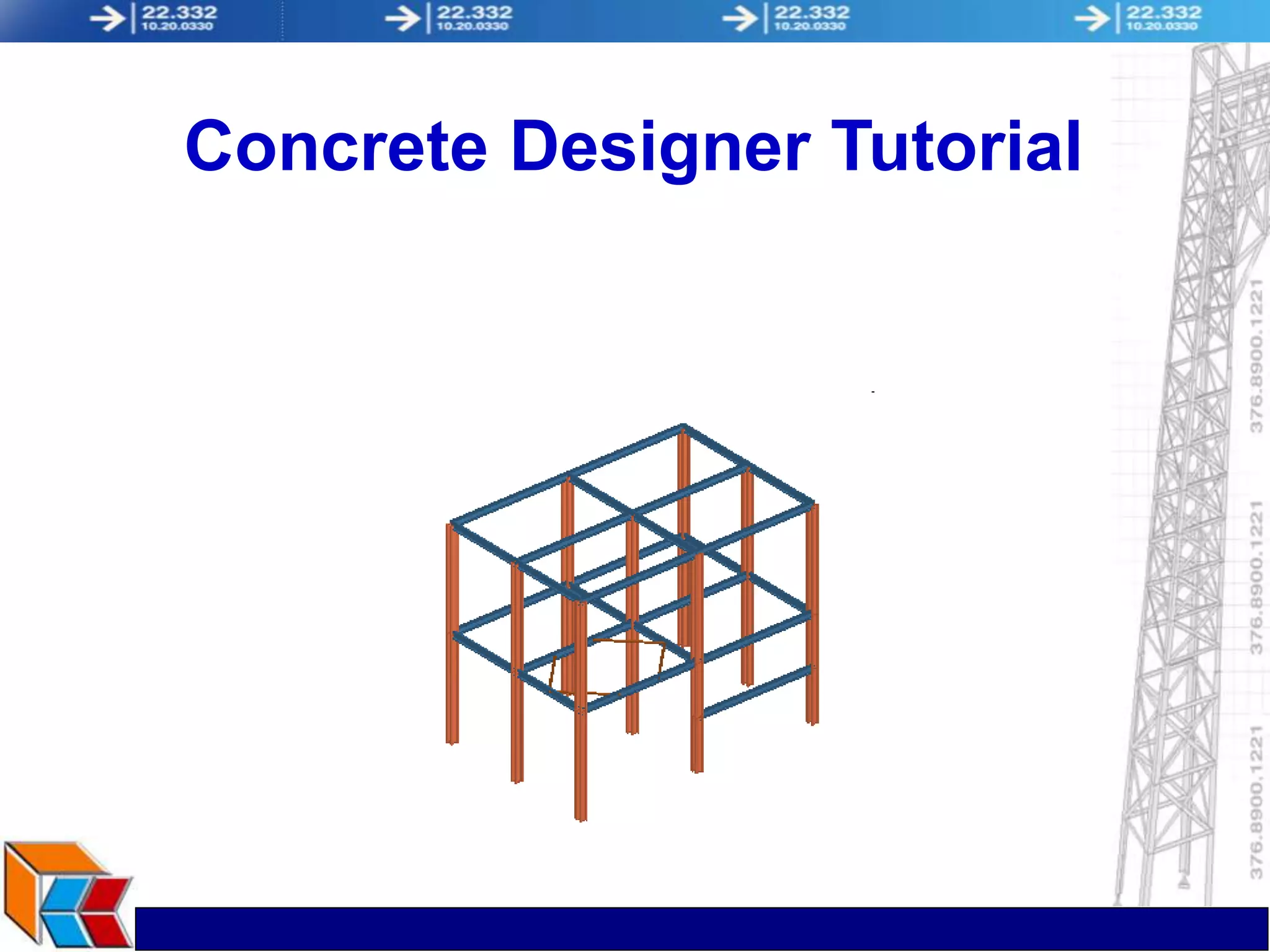
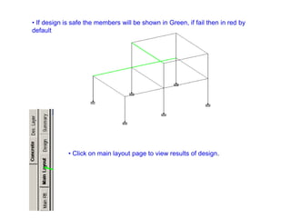
1) The document provides a tutorial on using a concrete design program with a worked example to design beams and columns.
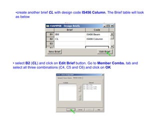
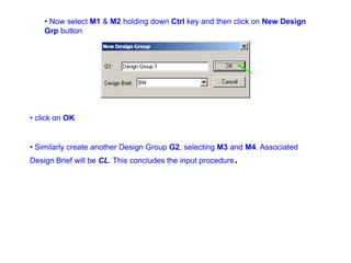
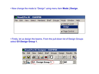
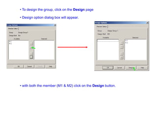
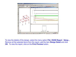
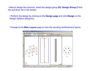
2) It outlines the steps to run the analysis, create load combinations, form members, create design groups and briefs, perform the design, and view results and a design report.
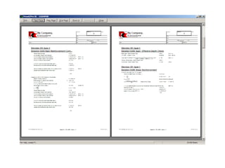
3) The key steps are to run the analysis, create load combinations, form members like beams and columns, assign design codes and combinations to briefs, assign members to design groups, perform the design, and review results and a design details report.