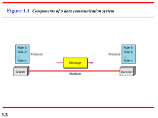
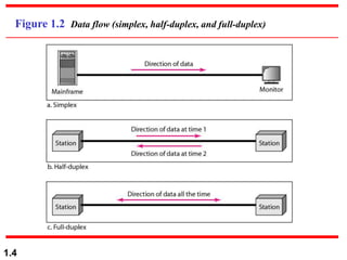
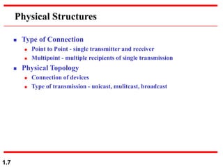
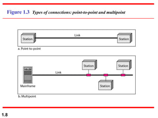
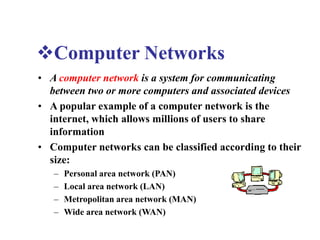
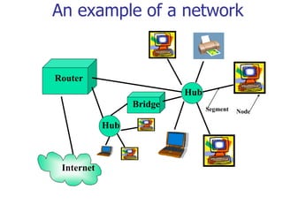
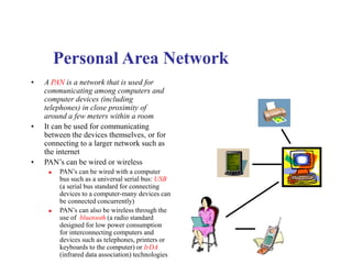
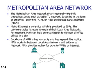
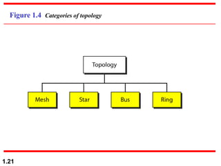
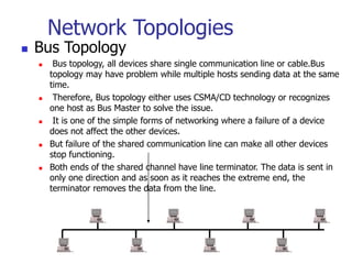
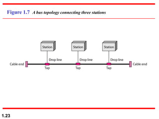
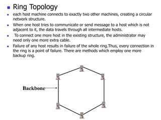
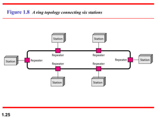
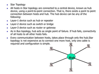
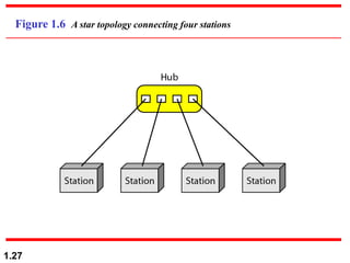
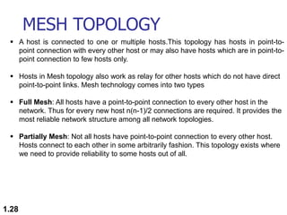
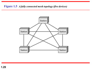
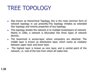
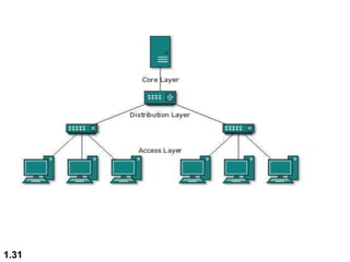
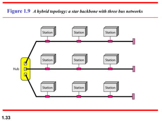
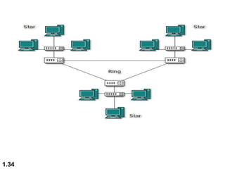
1.1
Chapter 1
Introduction
 COMPUTER NETWORK
1.2
1-1 DATA COMMUNICATIONS
The term telecommunication means communication at a
distance. The word data refers to information presented
in whatever form is agreed upon by the parties creating
and using the data. Data communications are the
exchange of data between two devices via some form of
transmission medium such as a wire cable.
 Components of a data communications system
 Data Flow
Topics discussed in this section:
1.3
Figure 1.1 Components of a data communication system
1.4
Figure 1.2 Data flow (simplex, half-duplex, and full-duplex)
1.5
1-2 NETWORKS
A network is a set of devices (often referred to as nodes)
connected by communication links. A node can be a
computer, printer, or any other device capable of sending
and/or receiving data generated by other nodes on the
network. A link can be a cable, air, optical fiber, or any
medium which can transport a signal carrying
information.
 Network Criteria
 Physical Structures
 Categories of Networks
Topics discussed in this section:
1.6
Network Criteria
 Performance
 Depends on Network Elements
 Measured in terms of Delay and Throughput
 Reliability
 Failure rate of network components
 Measured in terms of availability/robustness
 Security
 Data protection against corruption/loss of data due to:
 Errors
 Malicious users
1.7
Physical Structures
 Type of Connection
 Point to Point - single transmitter and receiver
 Multipoint - multiple recipients of single transmission
 Physical Topology
 Connection of devices
 Type of transmission - unicast, mulitcast, broadcast
1.8
Figure 1.3 Types of connections: point-to-point and multipoint
Computer Networks
• A computer network is a system for communicating
between two or more computers and associated devices
• A popular example of a computer network is the
internet, which allows millions of users to share
information
• Computer networks can be classified according to their
size:
– Personal area network (PAN)
– Local area network (LAN)
– Metropolitan area network (MAN)
– Wide area network (WAN)
Router
An example of a network
Internet
Segment Node
Hub
Hub
Bridge
Personal Area Network
• A PAN is a network that is used for
communicating among computers and
computer devices (including
telephones) in close proximity of
around a few meters within a room
• It can be used for communicating
between the devices themselves, or for
connecting to a larger network such as
the internet
• PAN’s can be wired or wireless
 PAN’s can be wired with a computer
bus such as a universal serial bus: USB
(a serial bus standard for connecting
devices to a computer-many devices can
be connected concurrently)
 PAN’s can also be wireless through the
use of bluetooth (a radio standard
designed for low power consumption
for interconnecting computers and
devices such as telephones, printers or
keyboards to the computer) or IrDA
(infrared data association) technologies
• A LAN is a network that is used for communicating
among computer devices, usually within an office
building or home
• LAN’s enable the sharing of resources such as files or
hardware devices that may be needed by multiple users
• Is limited in size, typically spanning a few hundred
meters, and no more than a mile
• Is very fast, with speeds from 10 Mbps to 10 Gbps
• Requires very little wiring, typically a single cable
connecting to each device
• Has lower cost compared to MAN’s or WAN’s
Local Area Network
LAN basics
 LAN’s can either be made wired or wireless. Twisted pair, coax or fiber optic cable can be
used in wired LAN’s
 Nodes in a LAN are linked together with a certain topology. These topologies include:
 Bus
 Ring
 Star
 Branching tree
 A node is defined to be any device connected to the network. This could be a computer, a
printer etc.
 A Hub is a networking device that connects multiple segments of the network together
 A Network Interface Card (NIC) is the circuit board that is used to connect computers to the
network. In most cases, this is an Ethernet card plugged in a computer’s motherboard
 The Network Operating System (NOS) is the software that enables users to share files and
hardware and communicate with other computers. Examples of NOS include: Windows XP,
Windows NT, Sun Solaris, Linux, etc..
 Resource sharing in a LAN is accomplished with different access methods. These include:
 Token based access
 CSMA/CD
METROPOLITAN AREA NETWROK
 The Metropolitan Area Network (MAN) generally expands
throughout a city such as cable TV network. It can be in the form
of Ethernet,Token-ring, ATM, or Fiber Distributed Data Interface
(FDDI).
 Metro Ethernet is a service which is provided by ISPs. This
service enables its users to expand their Local Area Networks.
For example, MAN can help an organization to connect all of its
offices in a city.
 Backbone of MAN is high-capacity and high-speed fiber optics.
MAN works in between Local Area Network and Wide Area
Network. MAN provides uplink for LANs to WANs or internet.
1.14
WIDE AREA NETWORK
 As the name suggests,the Wide Area Network (WAN) covers a
wide area which may span across provinces and even a whole
country.
 Generally, telecommunication networks are Wide Area Network.
These networks provide connectivity to MANs and LANs. Since
they are equipped with very high speed backbone, WANs use
very expensive network equipment.
 WAN may use advanced technologies such as Asynchronous
Transfer Mode (ATM), Frame Relay, and Synchronous Optical
Network (SONET). WAN may be managed by multiple
administration.
1.15
1.16
1.17
ATM Machine working
1.18
Debit/Credit Card
INTERNETWORK
 A network of networks is called an internetwork, or simply the
internet.
 It is the largest network in existence on this planet.
 The internet hugely connects all WANs and it can have connection to
LANs and Home networks. Internet uses TCP/IP protocol suite and
uses IP as its addressing protocol.
 Present day, Internet is widely implemented using IPv4. Because of
shortage of address spaces, it is gradually migrating from IPv4 to IPv6.
 Internet enables its users to share and access enormous amount of
information worldwide. It uses WWW, FTP, email services, audio and
video streaming etc. At huge level, internet works on Client-Server
model.
 Internet uses very high speed backbone of fiber optics. To inter-
connect various continents, fibers are laid under sea known to us as
submarine communication cable.
1.19
1.20
 Internet is widely deployed on World Wide Web services using HTML
linked pages and is accessible by client software known as Web
Browsers.
 When a user requests a page using some web browser located on
some Web Server anywhere in the world, the Web Server responds with
the proper HTML page. The communication delay is very low.
 Internet is serving many proposes and is involved in many aspects of
life. Some of them are:
 Web sites
 E-mail
 Instant Messaging
 Blogging
 Social Media
 Marketing
 Networking
 Resource Sharing
 Audio and Video Streaming
1.21
Figure 1.4 Categories of topology
Network Topologies
 Bus Topology
 Bus topology, all devices share single communication line or cable.Bus
topology may have problem while multiple hosts sending data at the same
time.
 Therefore, Bus topology either uses CSMA/CD technology or recognizes
one host as Bus Master to solve the issue.
 It is one of the simple forms of networking where a failure of a device
does not affect the other devices.
 But failure of the shared communication line can make all other devices
stop functioning.
 Both ends of the shared channel have line terminator. The data is sent in
only one direction and as soon as it reaches the extreme end, the
terminator removes the data from the line.
1.23
Figure 1.7 A bus topology connecting three stations
 Ring Topology
 each host machine connects to exactly two other machines, creating a circular
network structure.
 When one host tries to communicate or send message to a host which is not
adjacent to it, the data travels through all intermediate hosts.
 To connect one more host in the existing structure, the administrator may
need only one more extra cable.
 Failure of any host results in failure of the whole ring.Thus, every connection in
the ring is a point of failure. There are methods which employ one more
backup ring.
Backbone
1.25
Figure 1.8 A ring topology connecting six stations
 Star Topology
 All hosts in Star topology are connected to a central device, known as hub
device, using a point-to-point connection. That is, there exists a point to point
connection between hosts and hub. The hub device can be any of the
following:
 Layer-1 device such as hub or repeater
 Layer-2 device such as switch or bridge
 Layer-3 device such as router or gateway
 As in Bus topology, hub acts as single point of failure. If hub fails, connectivity
of all hosts to all other hosts fails.
 Every communication between hosts, takes place through only the hub.Star
topology is not expensive as to connect one more host, only one cable is
required and configuration is simple.
Hub
1.27
Figure 1.6 A star topology connecting four stations
MESH TOPOLOGY
1.28
 A host is connected to one or multiple hosts.This topology has hosts in point-to-
point connection with every other host or may also have hosts which are in point-to-
point connection to few hosts only.
 Hosts in Mesh topology also work as relay for other hosts which do not have direct
point-to-point links. Mesh technology comes into two types
 Full Mesh: All hosts have a point-to-point connection to every other host in the
network. Thus for every new host n(n-1)/2 connections are required. It provides the
most reliable network structure among all network topologies.
 Partially Mesh: Not all hosts have point-to-point connection to every other host.
Hosts connect to each other in some arbitrarily fashion. This topology exists where
we need to provide reliability to some hosts out of all.
1.29
Figure 1.5 A fully connected mesh topology (five devices)
TREE TOPOLOGY
 Also known as Hierarchical Topology, this is the most common form of
network topology in use presently.This topology imitates as extended
Star topology and inherits properties of bus topology.
 This topology divides the network in to multiple levels/layers of network.
Mainly in LANs, a network is bifurcated into three types of network
devices.
 The lowermost is access-layer where computers are attached. The
middle layer is known as distribution layer, which works as mediator
between upper layer and lower layer.
 The highest layer is known as core layer, and is central point of the
network, i.e. root of the tree from which all nodes fork.
1.30
1.31
HYBRID TOPOLOGY
 A network structure whose design contains more than one
topology is said to be hybrid topology. Hybrid topology inherits
merits and demerits of all the incorporating topologies.
 The combining topologies may contain attributes of Star, Ring,
Bus, and Daisy-chain topologies. Most WANs are connected by
means of Dual-Ring topology and networks connected to them
are mostly Star topology networks.
 Internet is the best example of largest Hybrid topology
1.32
1.33
Figure 1.9 A hybrid topology: a star backbone with three bus networks
1.34
Networking Devices
1.35
ND
HUB SWITCHES REPETERS ROUTERS BRIDGES GATEWAY
Seven layers of the OSI model
Hub/Repeater
Bridge/Switch
Router/Layer-3
Gateway
Gateway
HUB
 A hub, also called a network hub, is a common connection point
for devices in a network.
 Hubs are devices commonly used to connect segments of a LAN.
 The hub contains multiple ports. When a packet arrives at one port, it is
copied to the other ports so that all segments of the LAN can see all
packets.
 Hubs and switches serve as a central connection for all of your network
equipment and handles a data type known as frames. Frames carry your
data.
 When a frame is received, it is amplified and then transmitted on to the
port of the destination PC.
 Port 2/4/6/8 max.
1.37

1.38
• In a hub, a frame is passed along or “broadcast” to every one of its ports. It doesn’t
matter that the frame is only destined for one port.
• The hub has no way of distinguishing which port a frame should be sent to. Passing
it along to every port ensures that it will reach its intended destination.
• This places a lot of traffic on the network and can lead to poor network response
times.
• Compared to a standard switch, the hub is slower as it can send or receive
information just not at the same time, but typically costs more than a hub.
• Electrical signal or bits.
• Half Duplex.
• Can not Store MAC address.
• Always Broadcast.
• Single Collision Domain
• LAN Device.
• Active & Passive Hub.
PASSIVE & ACTIVE HUBS
 Active hub need electricity.
 Amplifies Signals.
 Regenerate Signals.
 Passive Hub do not require electricity.
 Simply receive and forward.
1.39
HOME AND SMALL BUSINESS
HUBS
 Hubs can be used as a standalone device or
connected to compatible hubs and switches to form
a larger network.
 Hubs are generally easy to install and maintain,
making these devices a good option for home
networking. A hub is also easily configured for
small business branch office networking.
1.40
REPEATER
 Kind of Active hub .
 Amplifies Signals.
 It Regenerate Signals.
 Works on LAN devices.
 Increase the length of connection
 10 base 2 = 185 meter.(so we can connect after certain
distance to increase the distance)
1.41
BRIDGE
 Bridge inspect incoming traffic and decide whether to
forward or reject .It check source & destination MAC
address.
 Layer -2 device.
 Used to connect multiple network segment or LAN
segment.
 Filter data traffic .
 Bridges reduce the amount of traffic on a LAN by dividing
it into two segment.
 It has 2 collision.
1.42
1.43
SWITCHES (Multi-port Bridge)
 Switches are intelligent devices. Switches are considered intelligent because
switches have memory in which switches maintain hardware address tables.
 These have the address of all hosts stored, as well as the host which is
connected to the switch through the port, is also stored.
 Hosts are used to connect each other under a switch LAN. You cannot connect
2 networks with the switch.
 The switch has the space to store your data where it checks to see the
incoming packet for any device.
 The physical address of all network devices is saved near the switch, after
checking them, the switch sends the information directly to that device and
without broadcasting the information.
 Layer-2 device , Full Duplex , Maintain CAM table.(content accessible
memory)
 First Broadcast then Unicast , Multicast.
 Every port of switch has separate collision domain.
 Switch has one broadcast domain (8/6/24/48).
1.44
WORKING OF SWITCHES
 Whenever a host sends a frame to any other host, then the
source host is stored with the port in the address table of the
MAC address switch.
 A switch always stores the address of the source in the table.
Unless a host does send some data, its MAC address and port
number will not be stored in the table of the switch.
 Unless a host does send some data, its MAC address and port
number will not be stored in the table of the switch.
 When you initialize the switch, the switch does not contain any
information about any host and its address. In such a situation,
when a host frame sends, its MAC address is stored in the table
but due to no destination information, the switch sends the
frame to all the hosts.
1.45
1.46
1. Store and forward :- The switch buffers and verifies each frame before
forwarding it Little bit slow but very reliable.
2. Cut through Switch :- The switch reads only upto to the frame hardware address
before starting to forward it no error checking.
3. Fragment free switch :- A method that attempt to retain the benefits of both
store and forward and cut through check first 64 bytes.
4. Adaptive switching :- A method of Automatically selecting between other three
mode.
ROUTERS
 The router forwards data packets along networks. It is connected to at
least two networks, commonly two LANs or WANs or a LAN and its
ISP’s network.
 Layer 3 device , based on WAN.
 Router Internetworking device , Maintain Routing Table
 Use IP address send in form of packets.
 Routers are located at gateways, the places where two or more
networks connect.
 Routers use headers and forwarding tables to determine the best path for
forwarding the packets, and they use protocols to communicate with
each other and configure the best route between any two hosts
 One of the key features of a packet is that it not only contains data, but
the destination address of where it’s going.
 A router will typically include a 4 to 8 port Ethernet switch (or hub) and
a Network Address Translator (NAT)
1.47
GATEWAY
 A Gateway is a connecting device used to
connect remote networks with the host
network Generally it acts as a Entry or Exit
point. Mostly Gateway operators at
application layer.
 Example University
1.48

Computer_Network_Basic.ppt

  • 1.
  • 2.
    1.2 1-1 DATA COMMUNICATIONS Theterm telecommunication means communication at a distance. The word data refers to information presented in whatever form is agreed upon by the parties creating and using the data. Data communications are the exchange of data between two devices via some form of transmission medium such as a wire cable.  Components of a data communications system  Data Flow Topics discussed in this section:
  • 3.
    1.3 Figure 1.1 Componentsof a data communication system
  • 4.
    1.4 Figure 1.2 Dataflow (simplex, half-duplex, and full-duplex)
  • 5.
    1.5 1-2 NETWORKS A networkis a set of devices (often referred to as nodes) connected by communication links. A node can be a computer, printer, or any other device capable of sending and/or receiving data generated by other nodes on the network. A link can be a cable, air, optical fiber, or any medium which can transport a signal carrying information.  Network Criteria  Physical Structures  Categories of Networks Topics discussed in this section:
  • 6.
    1.6 Network Criteria  Performance Depends on Network Elements  Measured in terms of Delay and Throughput  Reliability  Failure rate of network components  Measured in terms of availability/robustness  Security  Data protection against corruption/loss of data due to:  Errors  Malicious users
  • 7.
    1.7 Physical Structures  Typeof Connection  Point to Point - single transmitter and receiver  Multipoint - multiple recipients of single transmission  Physical Topology  Connection of devices  Type of transmission - unicast, mulitcast, broadcast
  • 8.
    1.8 Figure 1.3 Typesof connections: point-to-point and multipoint
  • 9.
    Computer Networks • Acomputer network is a system for communicating between two or more computers and associated devices • A popular example of a computer network is the internet, which allows millions of users to share information • Computer networks can be classified according to their size: – Personal area network (PAN) – Local area network (LAN) – Metropolitan area network (MAN) – Wide area network (WAN)
  • 10.
    Router An example ofa network Internet Segment Node Hub Hub Bridge
  • 11.
    Personal Area Network •A PAN is a network that is used for communicating among computers and computer devices (including telephones) in close proximity of around a few meters within a room • It can be used for communicating between the devices themselves, or for connecting to a larger network such as the internet • PAN’s can be wired or wireless  PAN’s can be wired with a computer bus such as a universal serial bus: USB (a serial bus standard for connecting devices to a computer-many devices can be connected concurrently)  PAN’s can also be wireless through the use of bluetooth (a radio standard designed for low power consumption for interconnecting computers and devices such as telephones, printers or keyboards to the computer) or IrDA (infrared data association) technologies
  • 12.
    • A LANis a network that is used for communicating among computer devices, usually within an office building or home • LAN’s enable the sharing of resources such as files or hardware devices that may be needed by multiple users • Is limited in size, typically spanning a few hundred meters, and no more than a mile • Is very fast, with speeds from 10 Mbps to 10 Gbps • Requires very little wiring, typically a single cable connecting to each device • Has lower cost compared to MAN’s or WAN’s Local Area Network
  • 13.
    LAN basics  LAN’scan either be made wired or wireless. Twisted pair, coax or fiber optic cable can be used in wired LAN’s  Nodes in a LAN are linked together with a certain topology. These topologies include:  Bus  Ring  Star  Branching tree  A node is defined to be any device connected to the network. This could be a computer, a printer etc.  A Hub is a networking device that connects multiple segments of the network together  A Network Interface Card (NIC) is the circuit board that is used to connect computers to the network. In most cases, this is an Ethernet card plugged in a computer’s motherboard  The Network Operating System (NOS) is the software that enables users to share files and hardware and communicate with other computers. Examples of NOS include: Windows XP, Windows NT, Sun Solaris, Linux, etc..  Resource sharing in a LAN is accomplished with different access methods. These include:  Token based access  CSMA/CD
  • 14.
    METROPOLITAN AREA NETWROK The Metropolitan Area Network (MAN) generally expands throughout a city such as cable TV network. It can be in the form of Ethernet,Token-ring, ATM, or Fiber Distributed Data Interface (FDDI).  Metro Ethernet is a service which is provided by ISPs. This service enables its users to expand their Local Area Networks. For example, MAN can help an organization to connect all of its offices in a city.  Backbone of MAN is high-capacity and high-speed fiber optics. MAN works in between Local Area Network and Wide Area Network. MAN provides uplink for LANs to WANs or internet. 1.14
  • 15.
    WIDE AREA NETWORK As the name suggests,the Wide Area Network (WAN) covers a wide area which may span across provinces and even a whole country.  Generally, telecommunication networks are Wide Area Network. These networks provide connectivity to MANs and LANs. Since they are equipped with very high speed backbone, WANs use very expensive network equipment.  WAN may use advanced technologies such as Asynchronous Transfer Mode (ATM), Frame Relay, and Synchronous Optical Network (SONET). WAN may be managed by multiple administration. 1.15
  • 16.
  • 17.
  • 18.
  • 19.
    INTERNETWORK  A networkof networks is called an internetwork, or simply the internet.  It is the largest network in existence on this planet.  The internet hugely connects all WANs and it can have connection to LANs and Home networks. Internet uses TCP/IP protocol suite and uses IP as its addressing protocol.  Present day, Internet is widely implemented using IPv4. Because of shortage of address spaces, it is gradually migrating from IPv4 to IPv6.  Internet enables its users to share and access enormous amount of information worldwide. It uses WWW, FTP, email services, audio and video streaming etc. At huge level, internet works on Client-Server model.  Internet uses very high speed backbone of fiber optics. To inter- connect various continents, fibers are laid under sea known to us as submarine communication cable. 1.19
  • 20.
    1.20  Internet iswidely deployed on World Wide Web services using HTML linked pages and is accessible by client software known as Web Browsers.  When a user requests a page using some web browser located on some Web Server anywhere in the world, the Web Server responds with the proper HTML page. The communication delay is very low.  Internet is serving many proposes and is involved in many aspects of life. Some of them are:  Web sites  E-mail  Instant Messaging  Blogging  Social Media  Marketing  Networking  Resource Sharing  Audio and Video Streaming
  • 21.
  • 22.
    Network Topologies  BusTopology  Bus topology, all devices share single communication line or cable.Bus topology may have problem while multiple hosts sending data at the same time.  Therefore, Bus topology either uses CSMA/CD technology or recognizes one host as Bus Master to solve the issue.  It is one of the simple forms of networking where a failure of a device does not affect the other devices.  But failure of the shared communication line can make all other devices stop functioning.  Both ends of the shared channel have line terminator. The data is sent in only one direction and as soon as it reaches the extreme end, the terminator removes the data from the line.
  • 23.
    1.23 Figure 1.7 Abus topology connecting three stations
  • 24.
     Ring Topology each host machine connects to exactly two other machines, creating a circular network structure.  When one host tries to communicate or send message to a host which is not adjacent to it, the data travels through all intermediate hosts.  To connect one more host in the existing structure, the administrator may need only one more extra cable.  Failure of any host results in failure of the whole ring.Thus, every connection in the ring is a point of failure. There are methods which employ one more backup ring. Backbone
  • 25.
    1.25 Figure 1.8 Aring topology connecting six stations
  • 26.
     Star Topology All hosts in Star topology are connected to a central device, known as hub device, using a point-to-point connection. That is, there exists a point to point connection between hosts and hub. The hub device can be any of the following:  Layer-1 device such as hub or repeater  Layer-2 device such as switch or bridge  Layer-3 device such as router or gateway  As in Bus topology, hub acts as single point of failure. If hub fails, connectivity of all hosts to all other hosts fails.  Every communication between hosts, takes place through only the hub.Star topology is not expensive as to connect one more host, only one cable is required and configuration is simple. Hub
  • 27.
    1.27 Figure 1.6 Astar topology connecting four stations
  • 28.
    MESH TOPOLOGY 1.28  Ahost is connected to one or multiple hosts.This topology has hosts in point-to- point connection with every other host or may also have hosts which are in point-to- point connection to few hosts only.  Hosts in Mesh topology also work as relay for other hosts which do not have direct point-to-point links. Mesh technology comes into two types  Full Mesh: All hosts have a point-to-point connection to every other host in the network. Thus for every new host n(n-1)/2 connections are required. It provides the most reliable network structure among all network topologies.  Partially Mesh: Not all hosts have point-to-point connection to every other host. Hosts connect to each other in some arbitrarily fashion. This topology exists where we need to provide reliability to some hosts out of all.
  • 29.
    1.29 Figure 1.5 Afully connected mesh topology (five devices)
  • 30.
    TREE TOPOLOGY  Alsoknown as Hierarchical Topology, this is the most common form of network topology in use presently.This topology imitates as extended Star topology and inherits properties of bus topology.  This topology divides the network in to multiple levels/layers of network. Mainly in LANs, a network is bifurcated into three types of network devices.  The lowermost is access-layer where computers are attached. The middle layer is known as distribution layer, which works as mediator between upper layer and lower layer.  The highest layer is known as core layer, and is central point of the network, i.e. root of the tree from which all nodes fork. 1.30
  • 31.
  • 32.
    HYBRID TOPOLOGY  Anetwork structure whose design contains more than one topology is said to be hybrid topology. Hybrid topology inherits merits and demerits of all the incorporating topologies.  The combining topologies may contain attributes of Star, Ring, Bus, and Daisy-chain topologies. Most WANs are connected by means of Dual-Ring topology and networks connected to them are mostly Star topology networks.  Internet is the best example of largest Hybrid topology 1.32
  • 33.
    1.33 Figure 1.9 Ahybrid topology: a star backbone with three bus networks
  • 34.
  • 35.
    Networking Devices 1.35 ND HUB SWITCHESREPETERS ROUTERS BRIDGES GATEWAY
  • 36.
    Seven layers ofthe OSI model Hub/Repeater Bridge/Switch Router/Layer-3 Gateway Gateway
  • 37.
    HUB  A hub,also called a network hub, is a common connection point for devices in a network.  Hubs are devices commonly used to connect segments of a LAN.  The hub contains multiple ports. When a packet arrives at one port, it is copied to the other ports so that all segments of the LAN can see all packets.  Hubs and switches serve as a central connection for all of your network equipment and handles a data type known as frames. Frames carry your data.  When a frame is received, it is amplified and then transmitted on to the port of the destination PC.  Port 2/4/6/8 max. 1.37
  • 38.
     1.38 • In ahub, a frame is passed along or “broadcast” to every one of its ports. It doesn’t matter that the frame is only destined for one port. • The hub has no way of distinguishing which port a frame should be sent to. Passing it along to every port ensures that it will reach its intended destination. • This places a lot of traffic on the network and can lead to poor network response times. • Compared to a standard switch, the hub is slower as it can send or receive information just not at the same time, but typically costs more than a hub. • Electrical signal or bits. • Half Duplex. • Can not Store MAC address. • Always Broadcast. • Single Collision Domain • LAN Device. • Active & Passive Hub.
  • 39.
    PASSIVE & ACTIVEHUBS  Active hub need electricity.  Amplifies Signals.  Regenerate Signals.  Passive Hub do not require electricity.  Simply receive and forward. 1.39
  • 40.
    HOME AND SMALLBUSINESS HUBS  Hubs can be used as a standalone device or connected to compatible hubs and switches to form a larger network.  Hubs are generally easy to install and maintain, making these devices a good option for home networking. A hub is also easily configured for small business branch office networking. 1.40
  • 41.
    REPEATER  Kind ofActive hub .  Amplifies Signals.  It Regenerate Signals.  Works on LAN devices.  Increase the length of connection  10 base 2 = 185 meter.(so we can connect after certain distance to increase the distance) 1.41
  • 42.
    BRIDGE  Bridge inspectincoming traffic and decide whether to forward or reject .It check source & destination MAC address.  Layer -2 device.  Used to connect multiple network segment or LAN segment.  Filter data traffic .  Bridges reduce the amount of traffic on a LAN by dividing it into two segment.  It has 2 collision. 1.42
  • 43.
  • 44.
    SWITCHES (Multi-port Bridge) Switches are intelligent devices. Switches are considered intelligent because switches have memory in which switches maintain hardware address tables.  These have the address of all hosts stored, as well as the host which is connected to the switch through the port, is also stored.  Hosts are used to connect each other under a switch LAN. You cannot connect 2 networks with the switch.  The switch has the space to store your data where it checks to see the incoming packet for any device.  The physical address of all network devices is saved near the switch, after checking them, the switch sends the information directly to that device and without broadcasting the information.  Layer-2 device , Full Duplex , Maintain CAM table.(content accessible memory)  First Broadcast then Unicast , Multicast.  Every port of switch has separate collision domain.  Switch has one broadcast domain (8/6/24/48). 1.44
  • 45.
    WORKING OF SWITCHES Whenever a host sends a frame to any other host, then the source host is stored with the port in the address table of the MAC address switch.  A switch always stores the address of the source in the table. Unless a host does send some data, its MAC address and port number will not be stored in the table of the switch.  Unless a host does send some data, its MAC address and port number will not be stored in the table of the switch.  When you initialize the switch, the switch does not contain any information about any host and its address. In such a situation, when a host frame sends, its MAC address is stored in the table but due to no destination information, the switch sends the frame to all the hosts. 1.45
  • 46.
    1.46 1. Store andforward :- The switch buffers and verifies each frame before forwarding it Little bit slow but very reliable. 2. Cut through Switch :- The switch reads only upto to the frame hardware address before starting to forward it no error checking. 3. Fragment free switch :- A method that attempt to retain the benefits of both store and forward and cut through check first 64 bytes. 4. Adaptive switching :- A method of Automatically selecting between other three mode.
  • 47.
    ROUTERS  The routerforwards data packets along networks. It is connected to at least two networks, commonly two LANs or WANs or a LAN and its ISP’s network.  Layer 3 device , based on WAN.  Router Internetworking device , Maintain Routing Table  Use IP address send in form of packets.  Routers are located at gateways, the places where two or more networks connect.  Routers use headers and forwarding tables to determine the best path for forwarding the packets, and they use protocols to communicate with each other and configure the best route between any two hosts  One of the key features of a packet is that it not only contains data, but the destination address of where it’s going.  A router will typically include a 4 to 8 port Ethernet switch (or hub) and a Network Address Translator (NAT) 1.47
  • 48.
    GATEWAY  A Gatewayis a connecting device used to connect remote networks with the host network Generally it acts as a Entry or Exit point. Mostly Gateway operators at application layer.  Example University 1.48