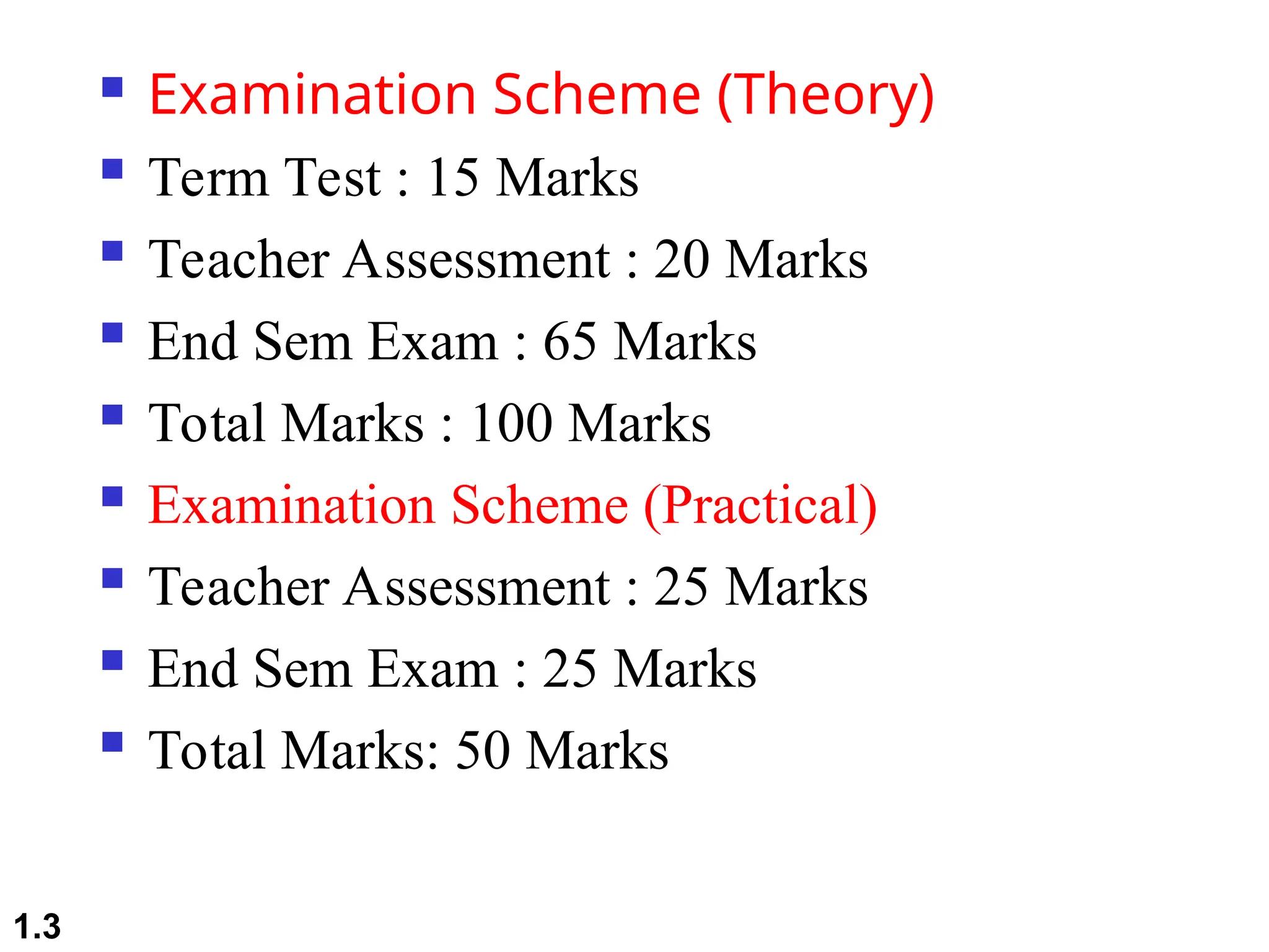
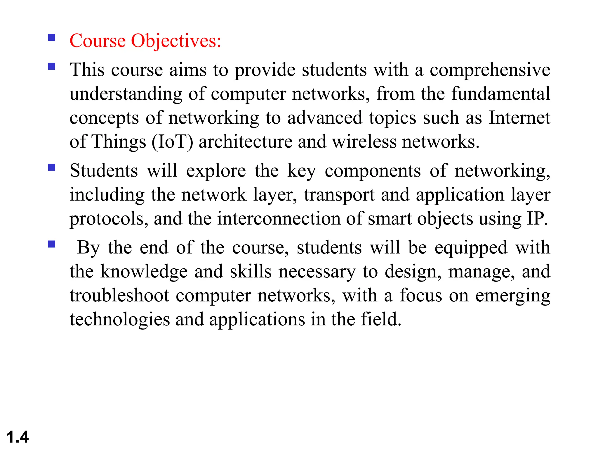
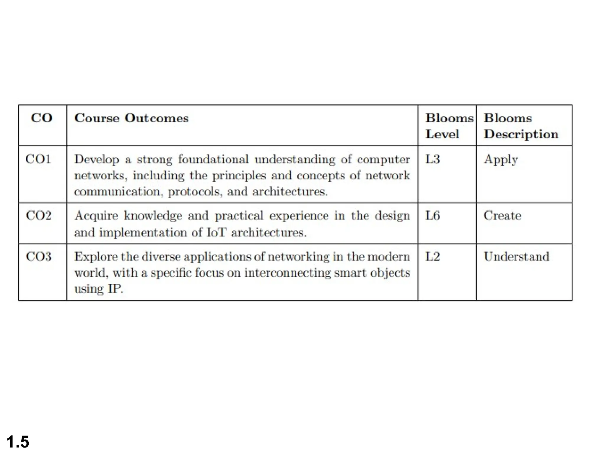
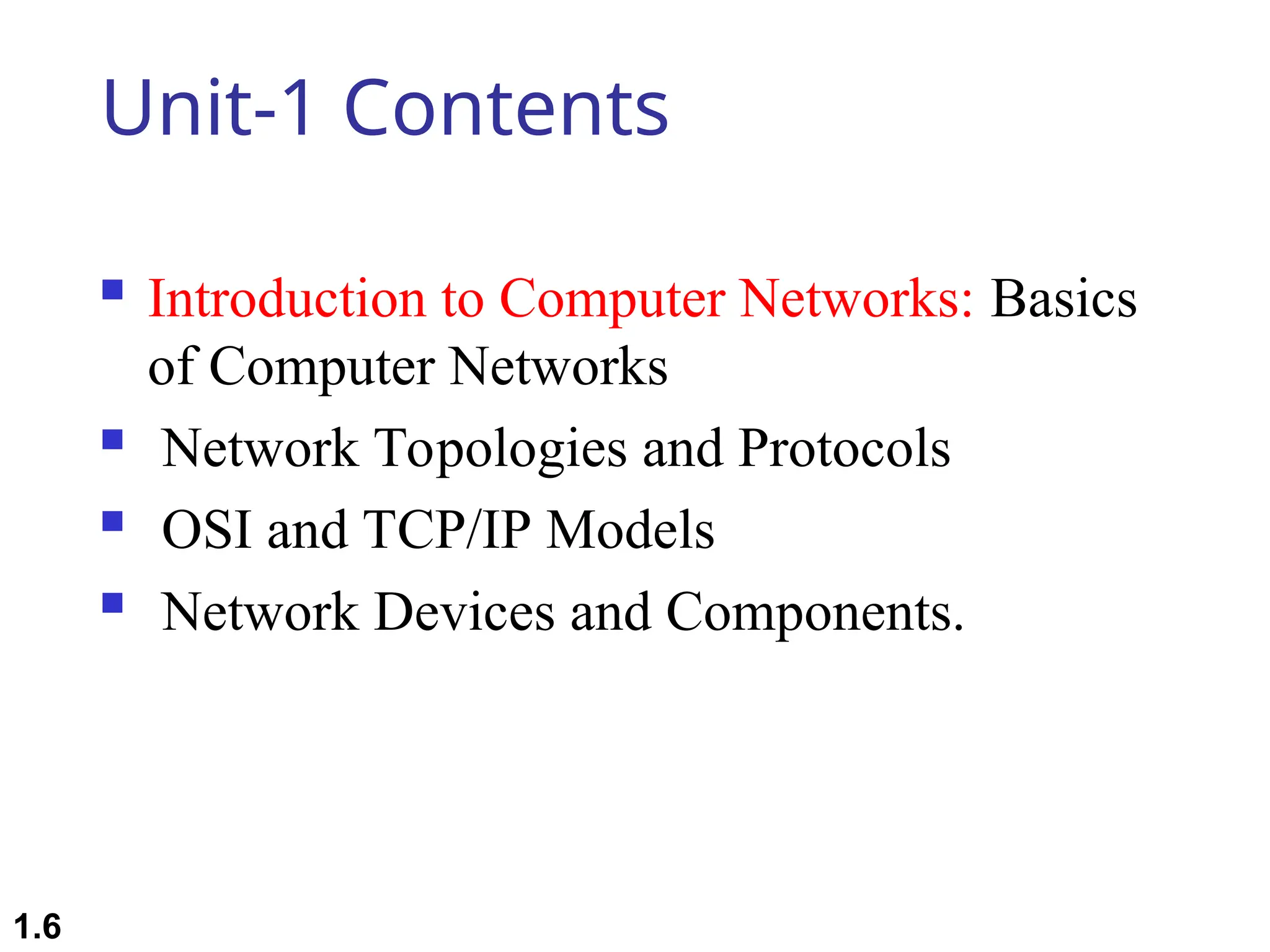
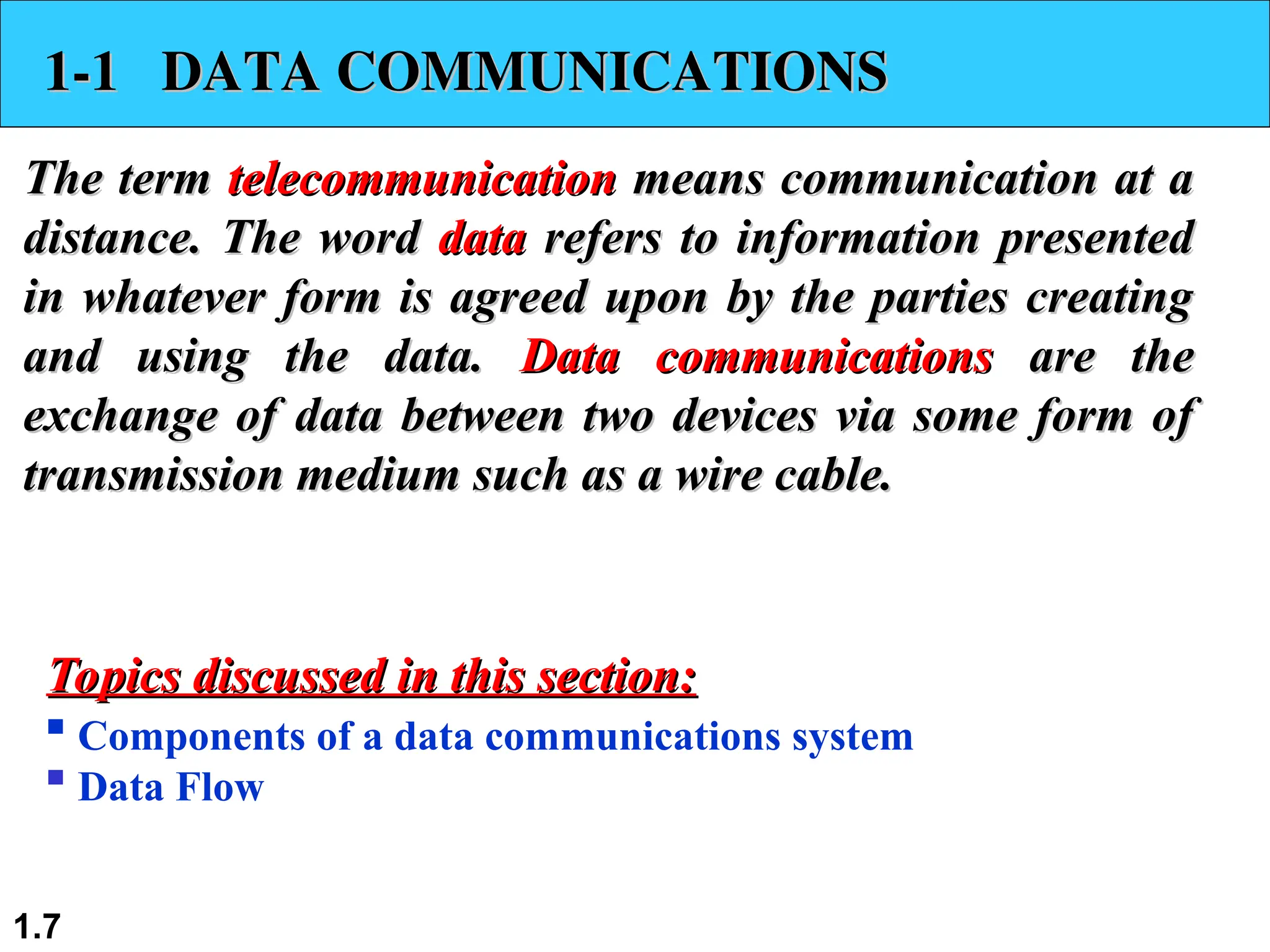
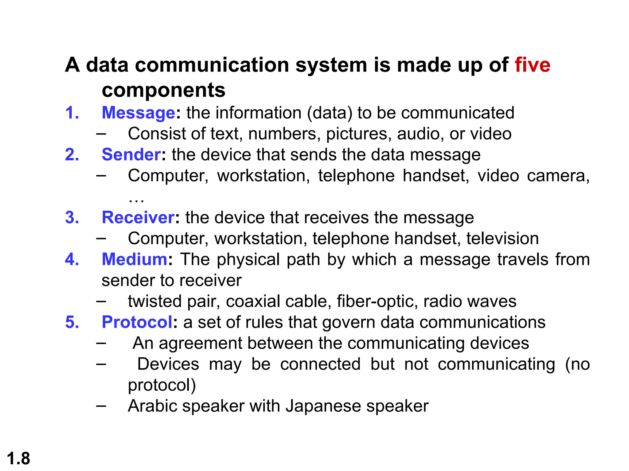
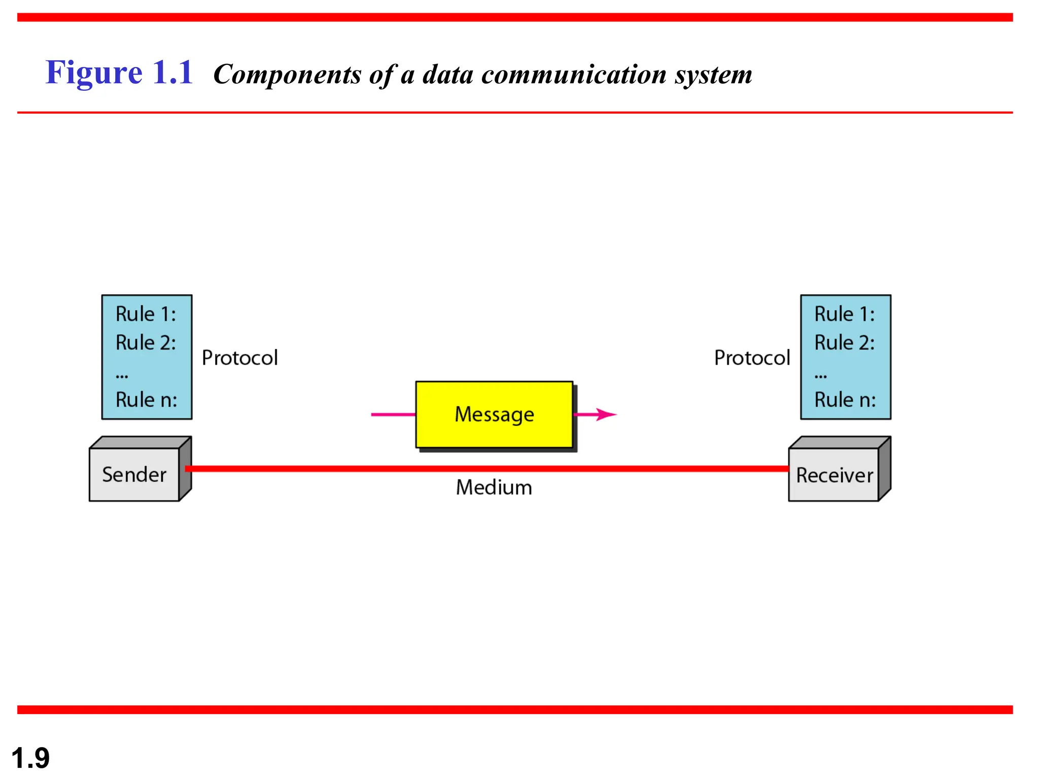
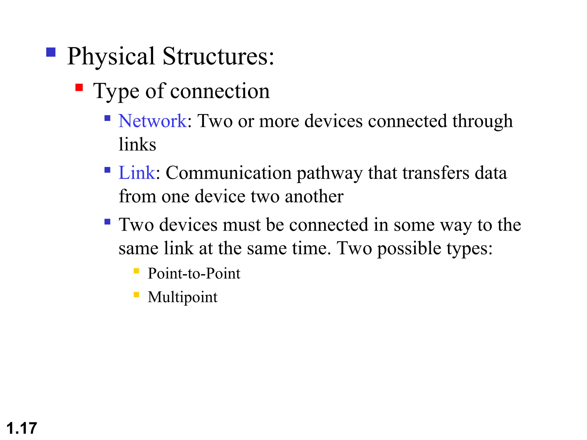
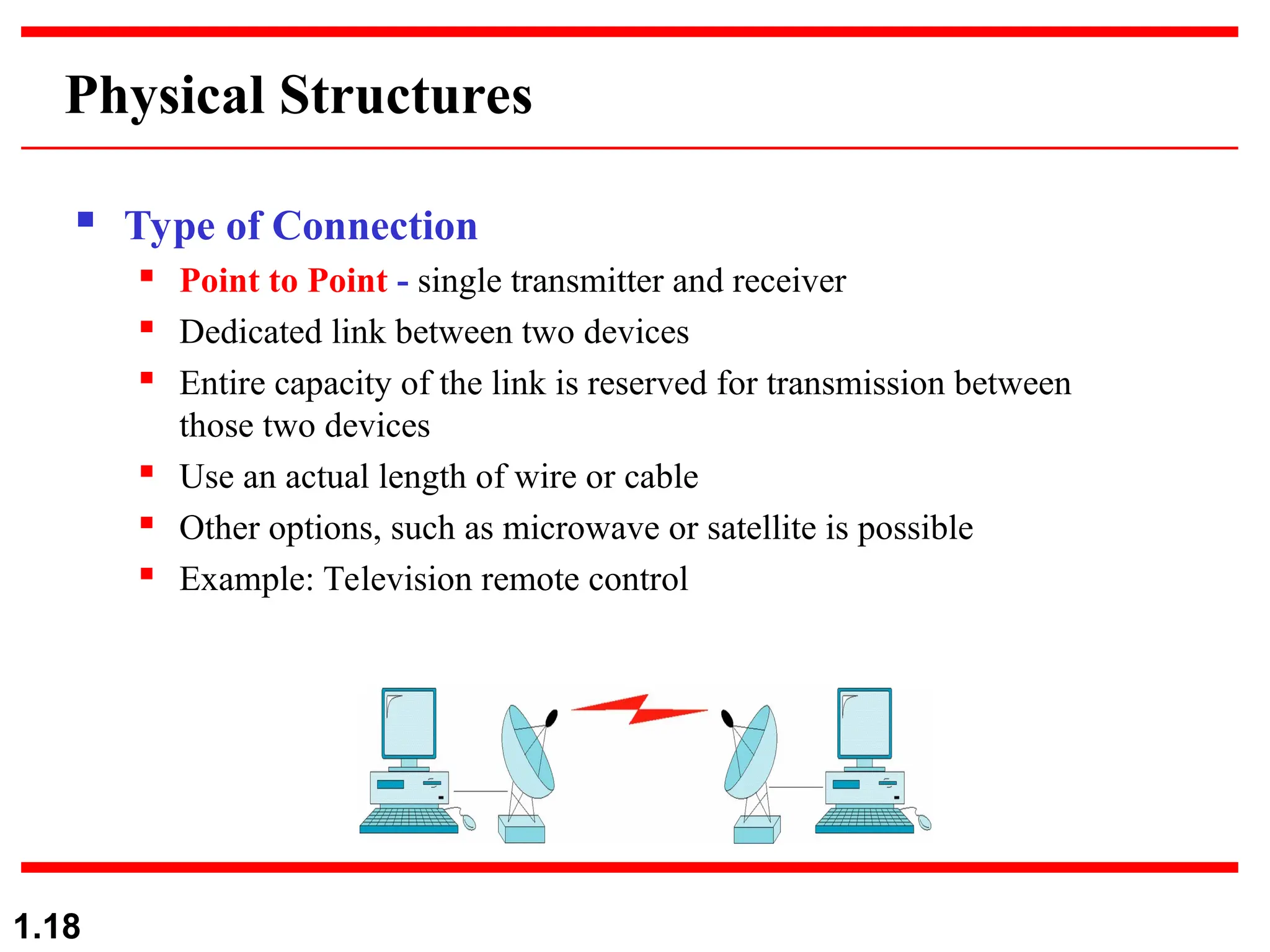
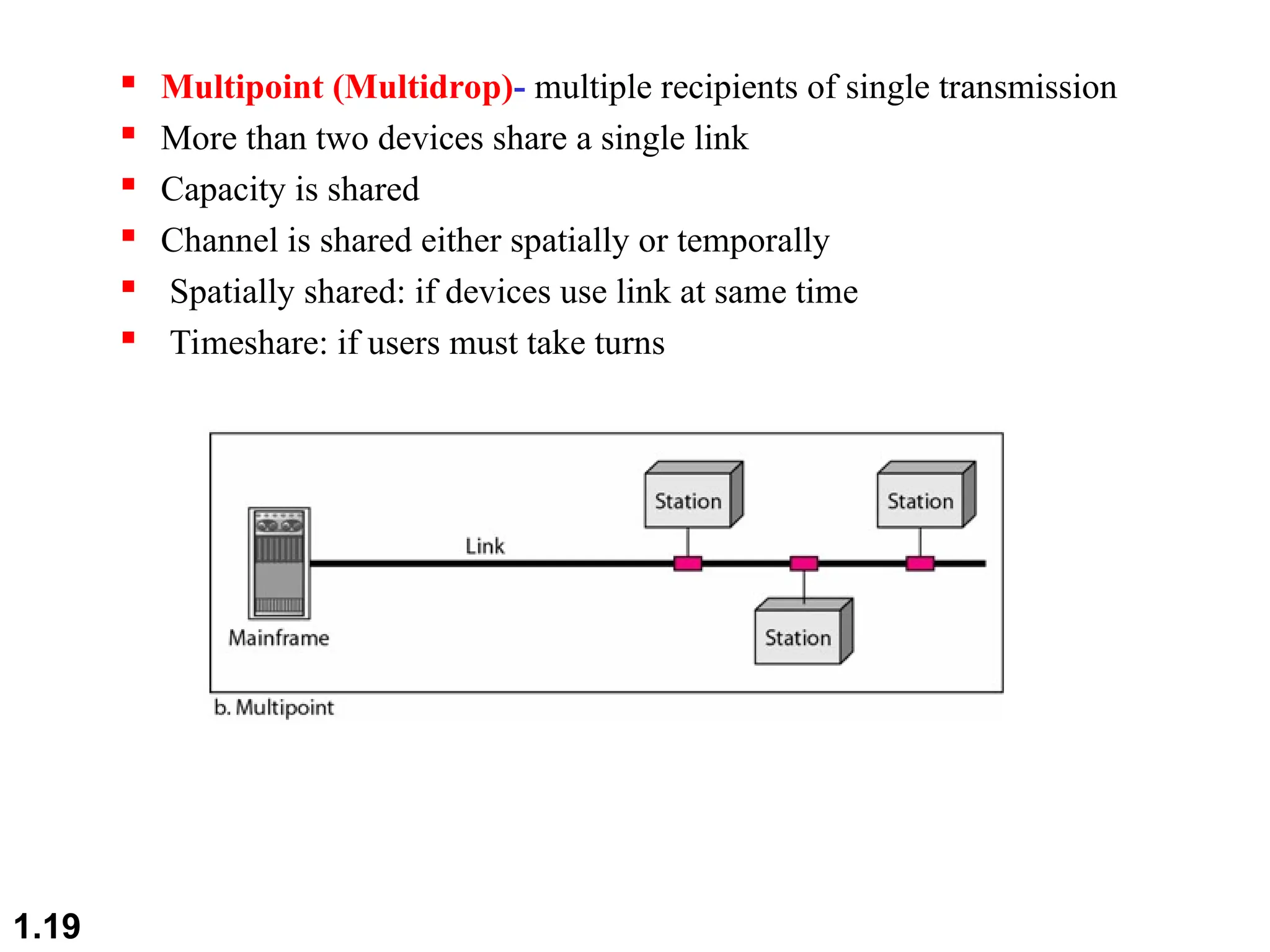
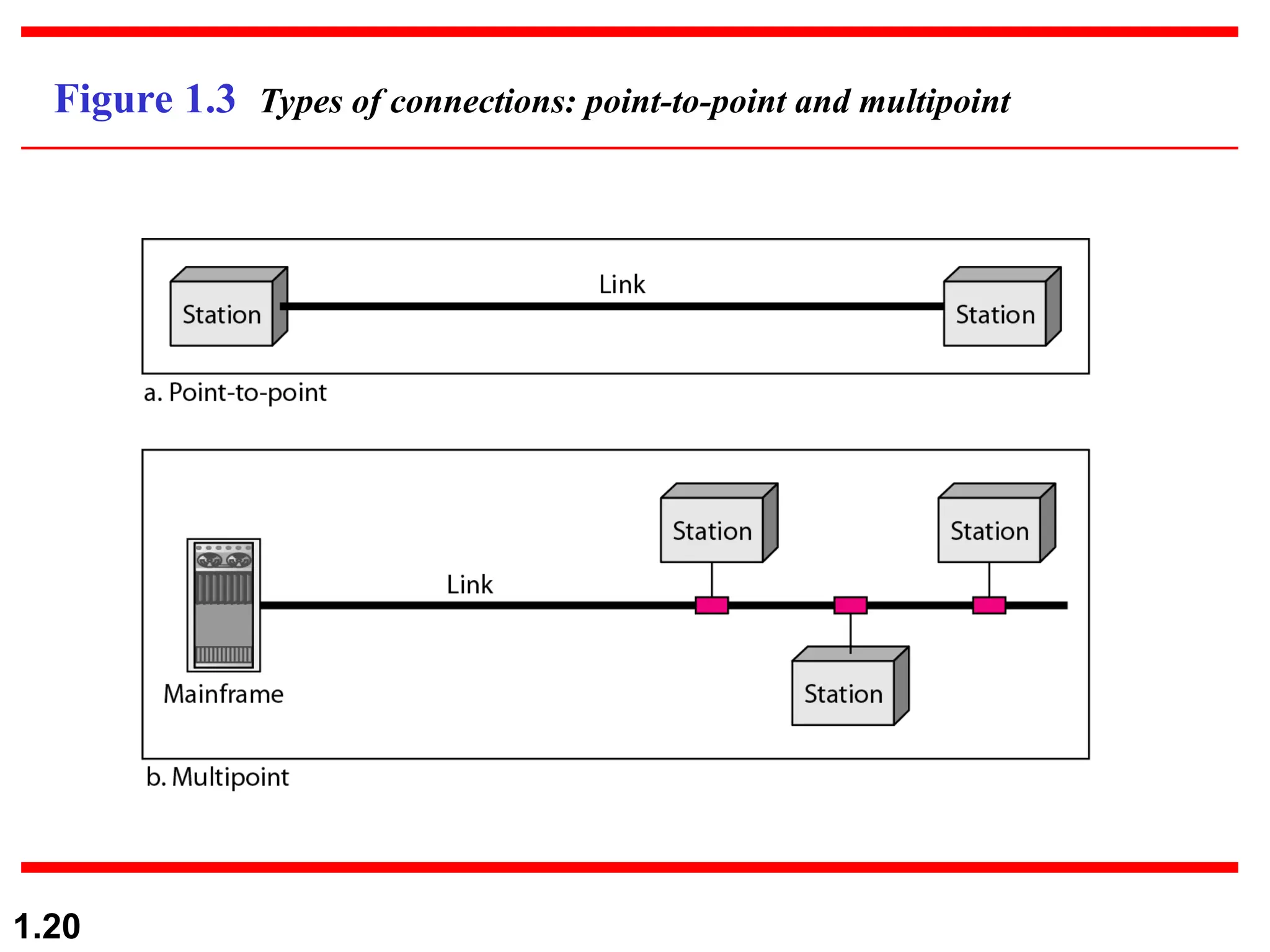
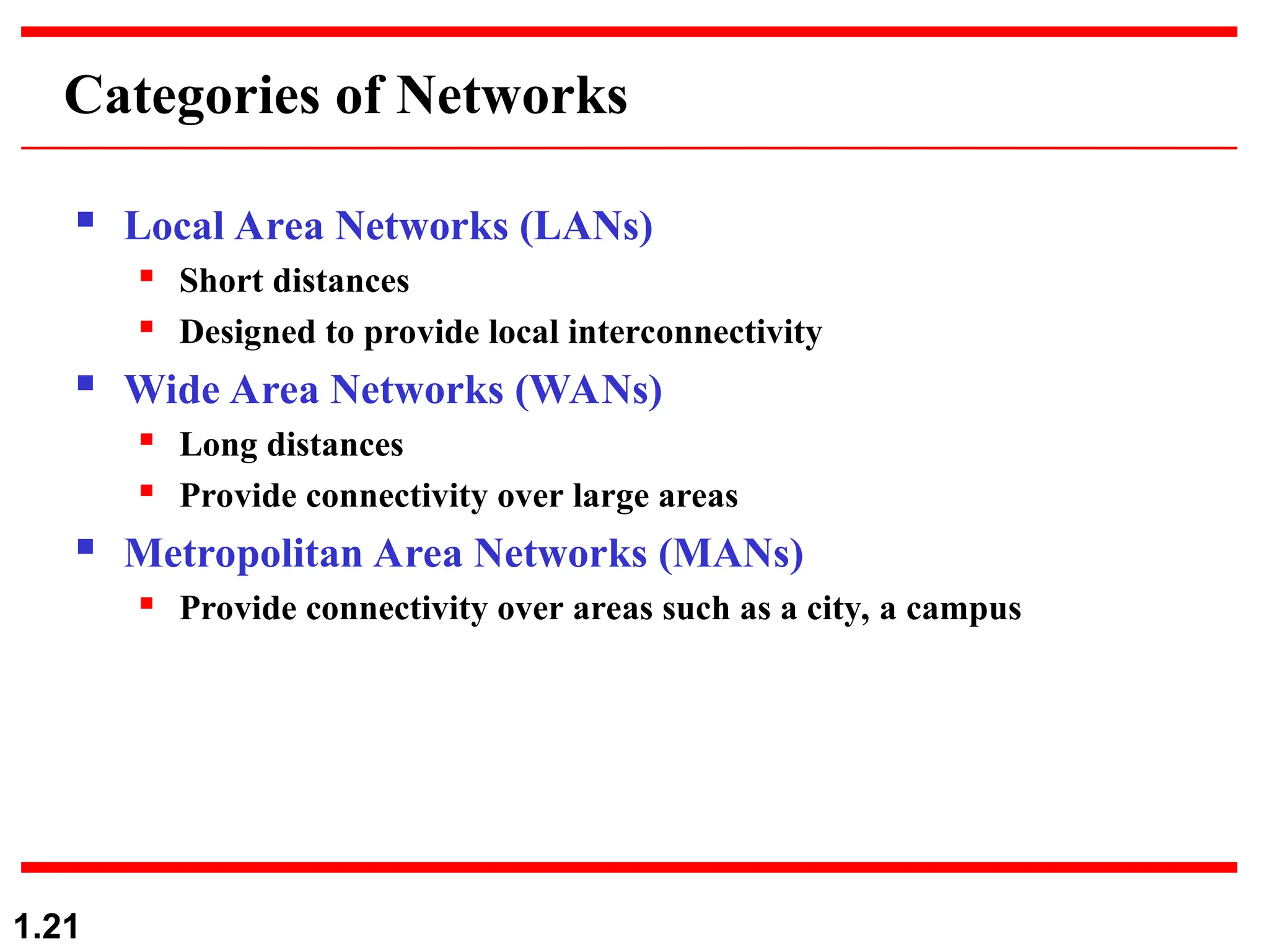
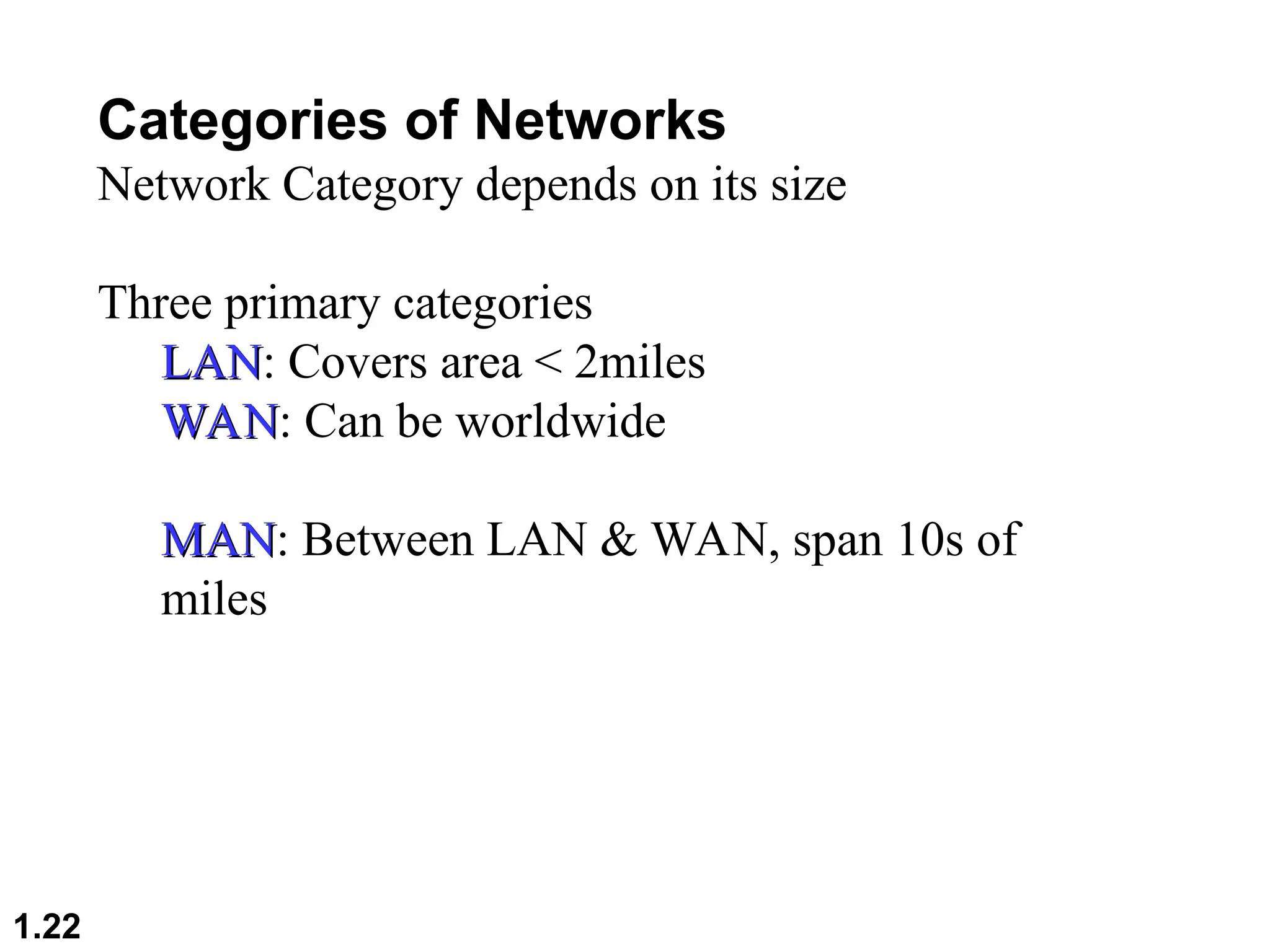
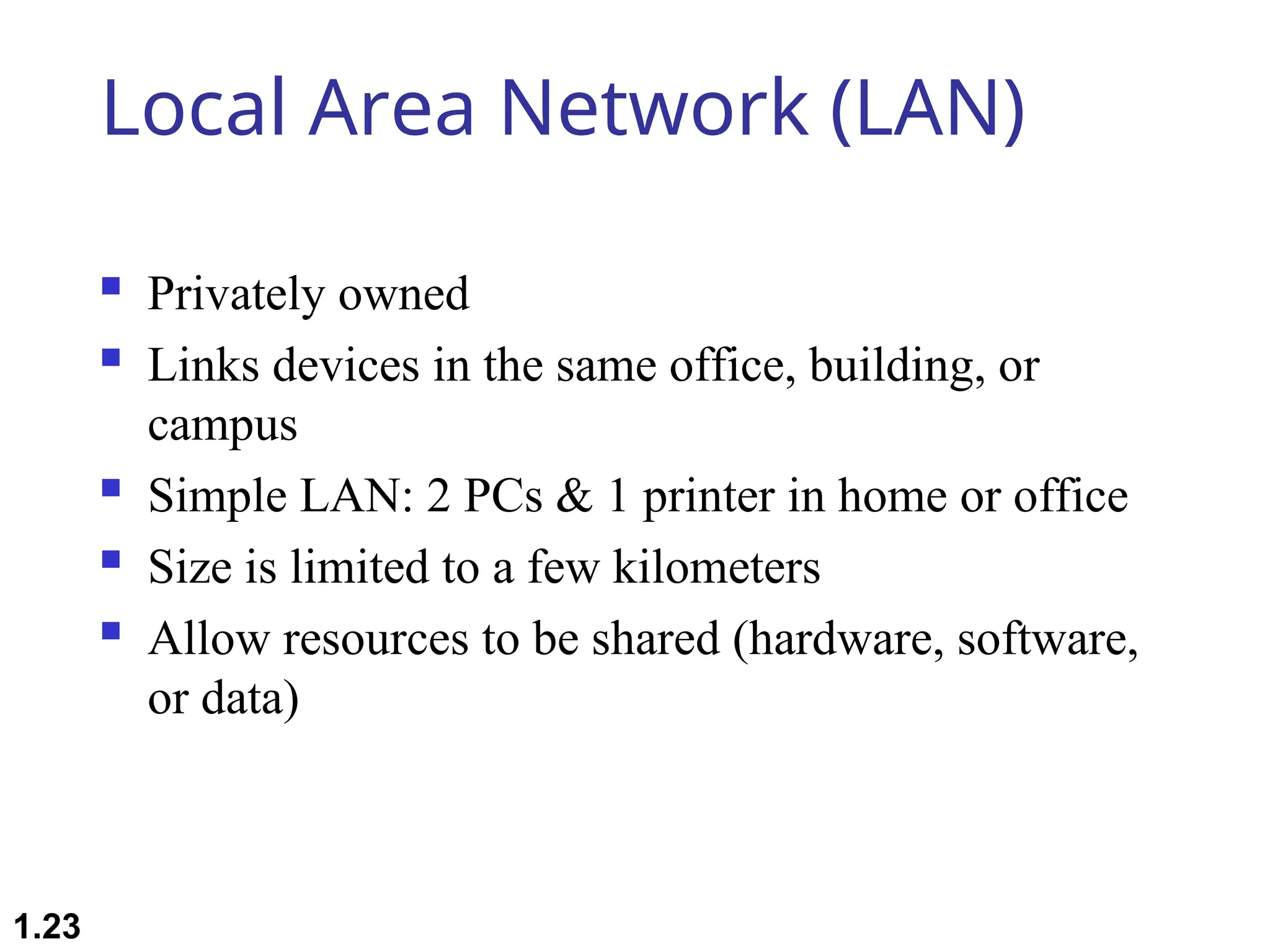
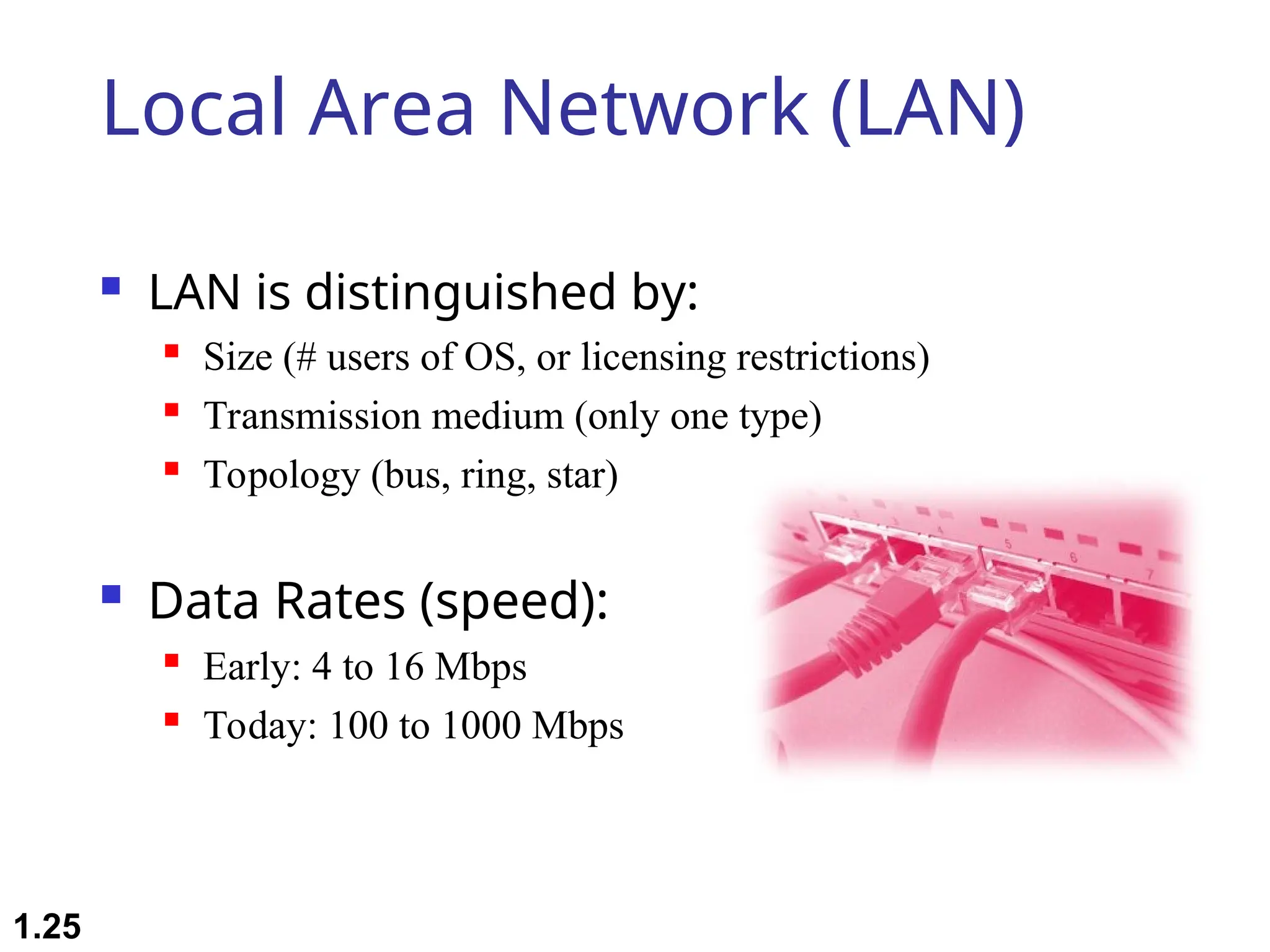
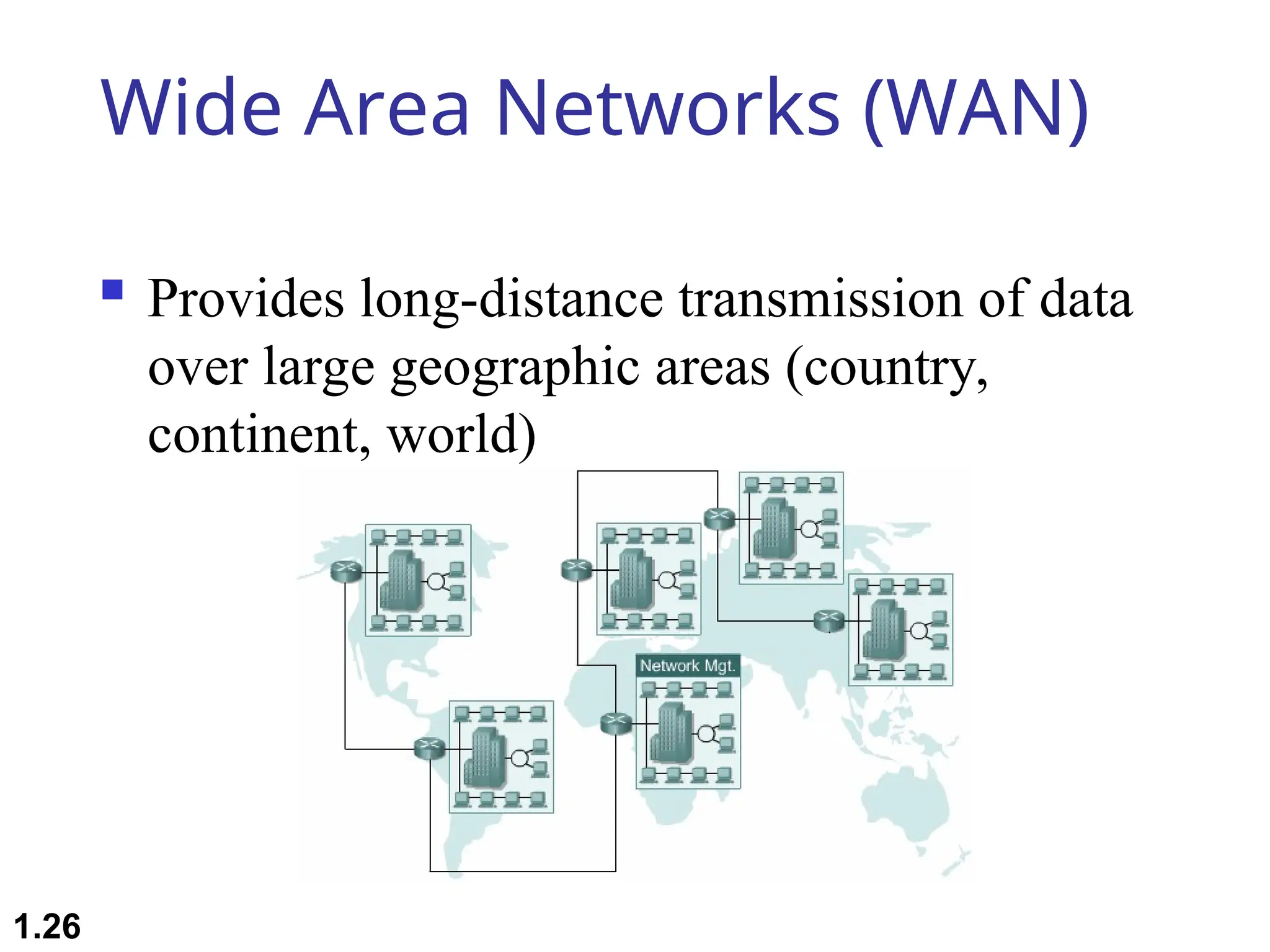
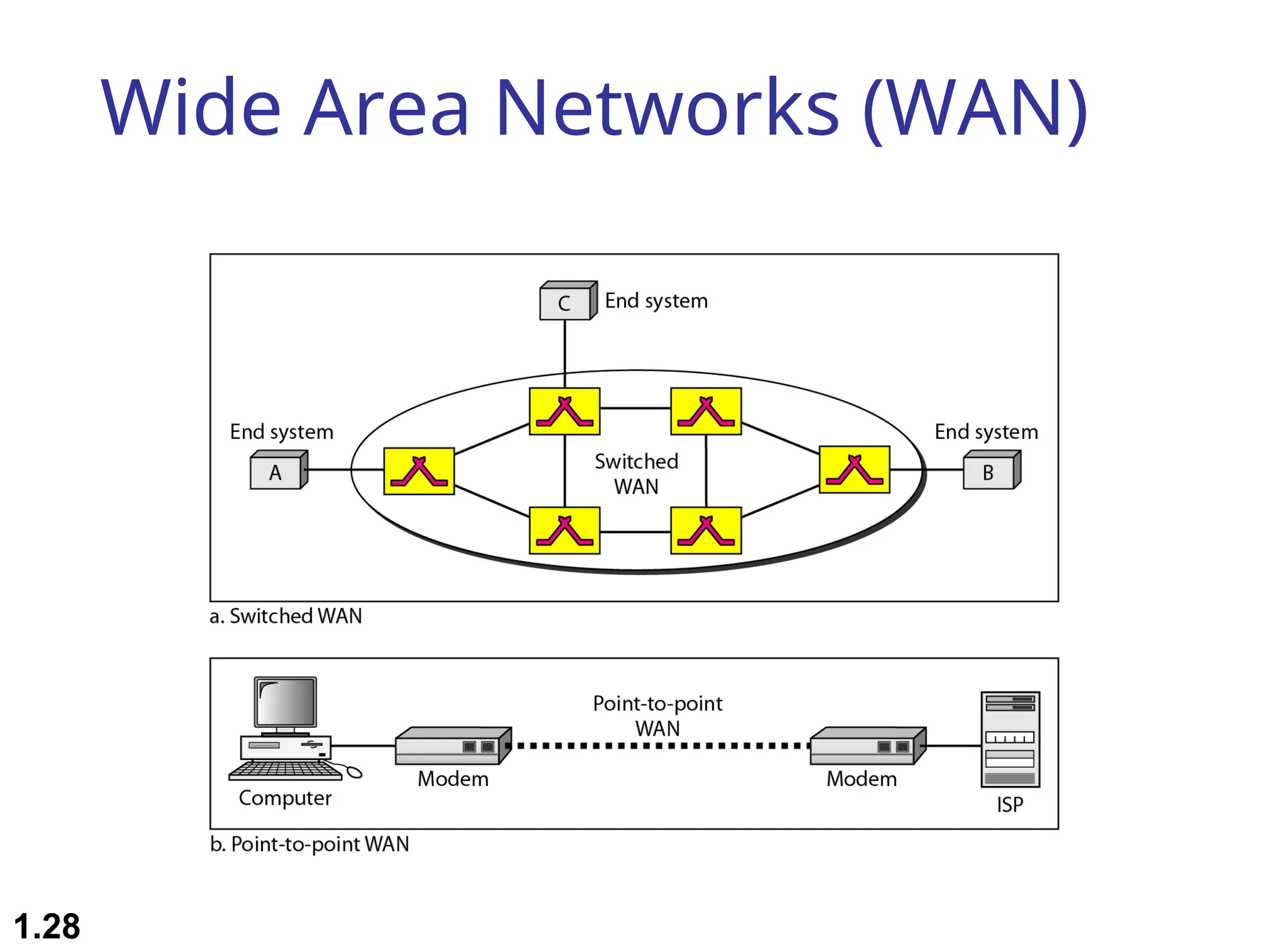
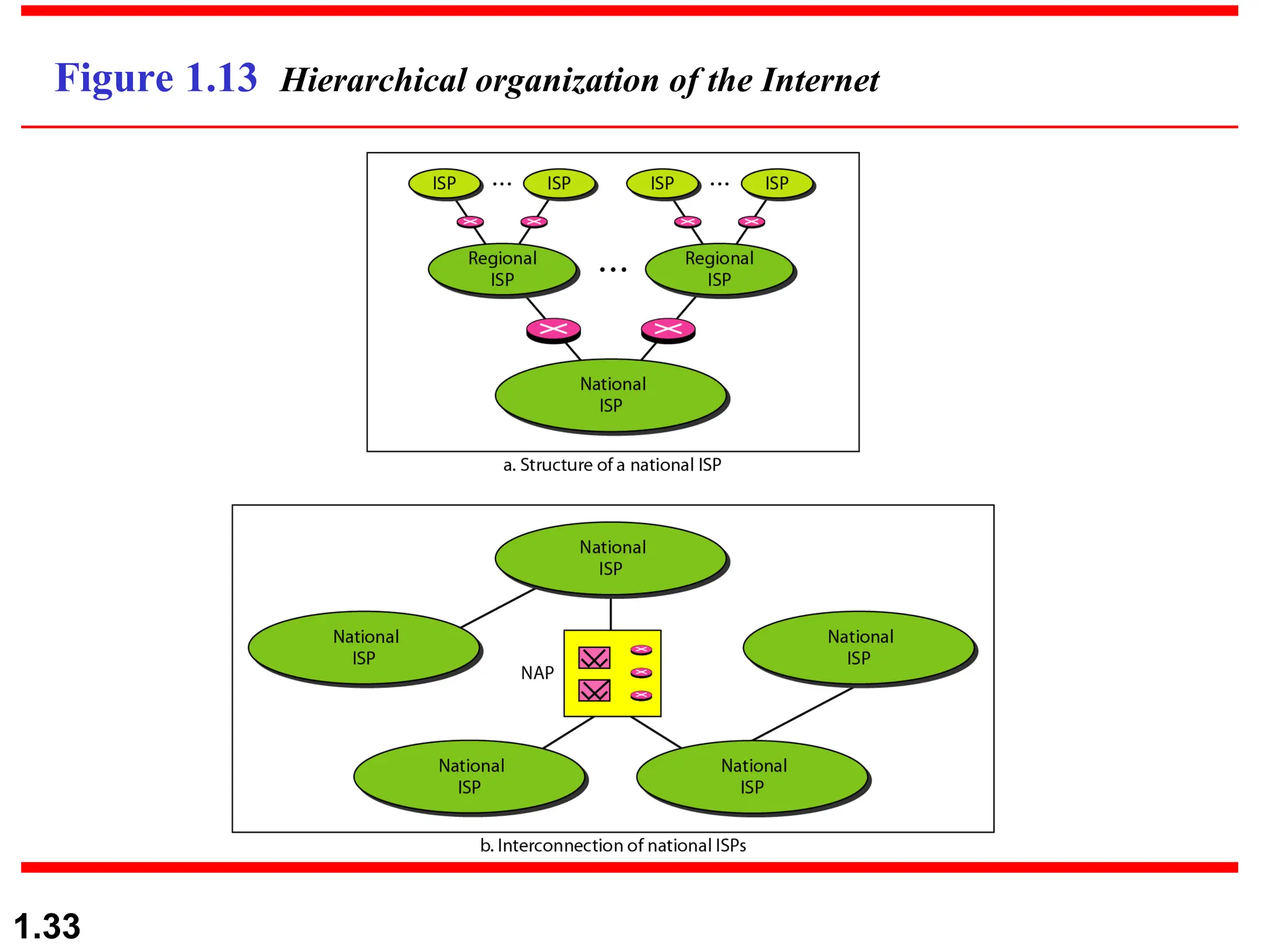
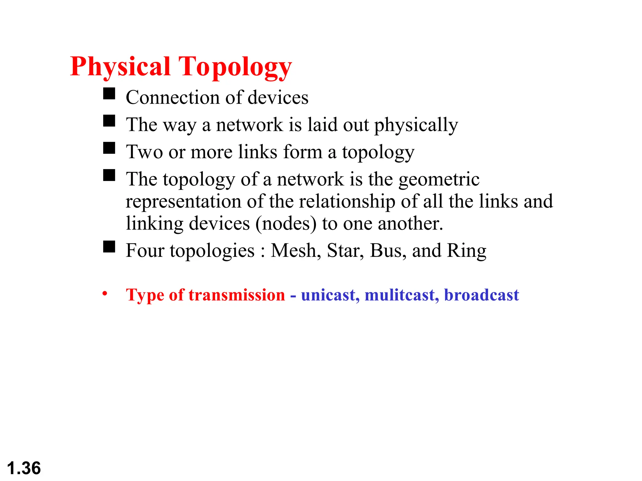
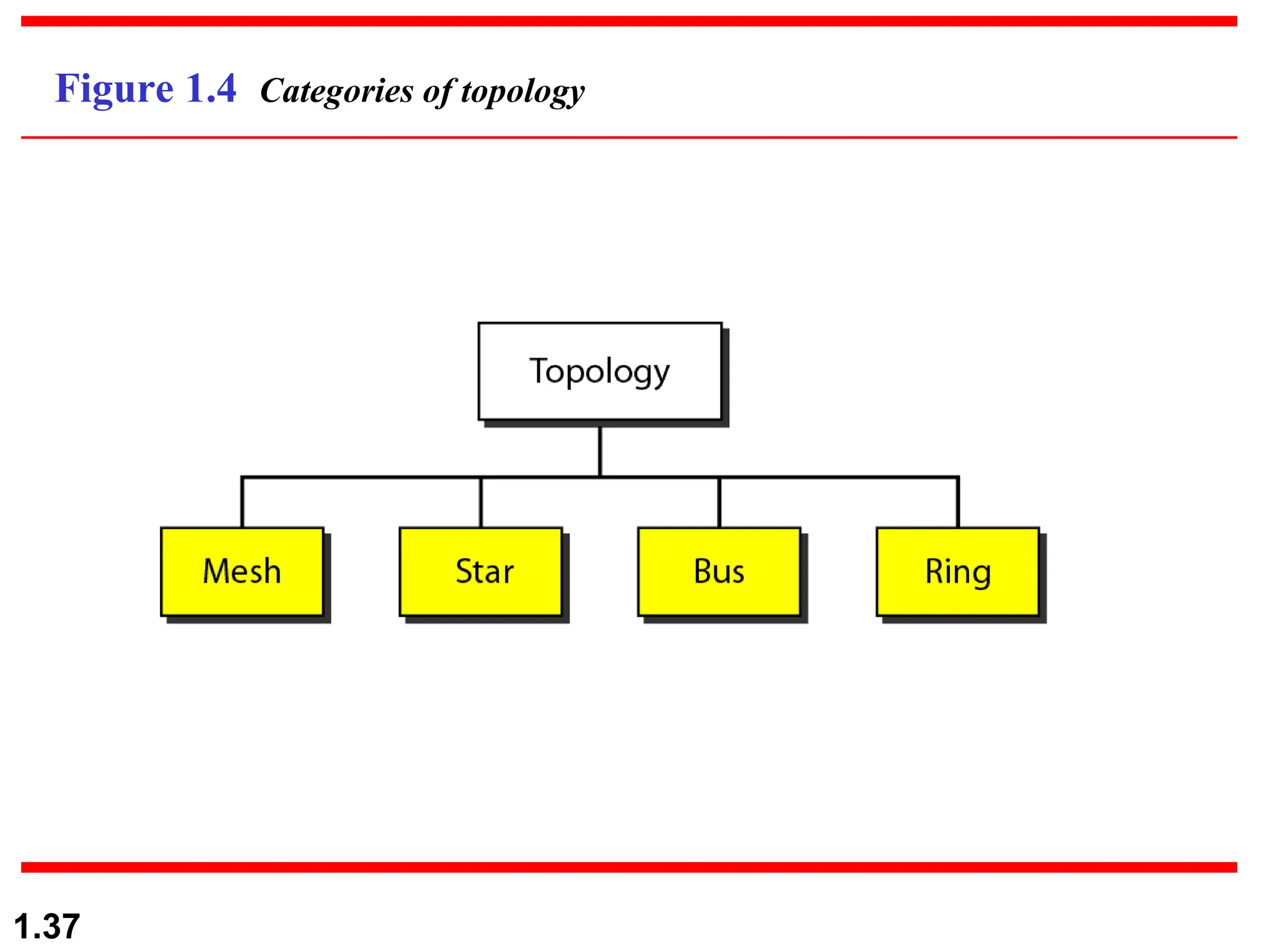
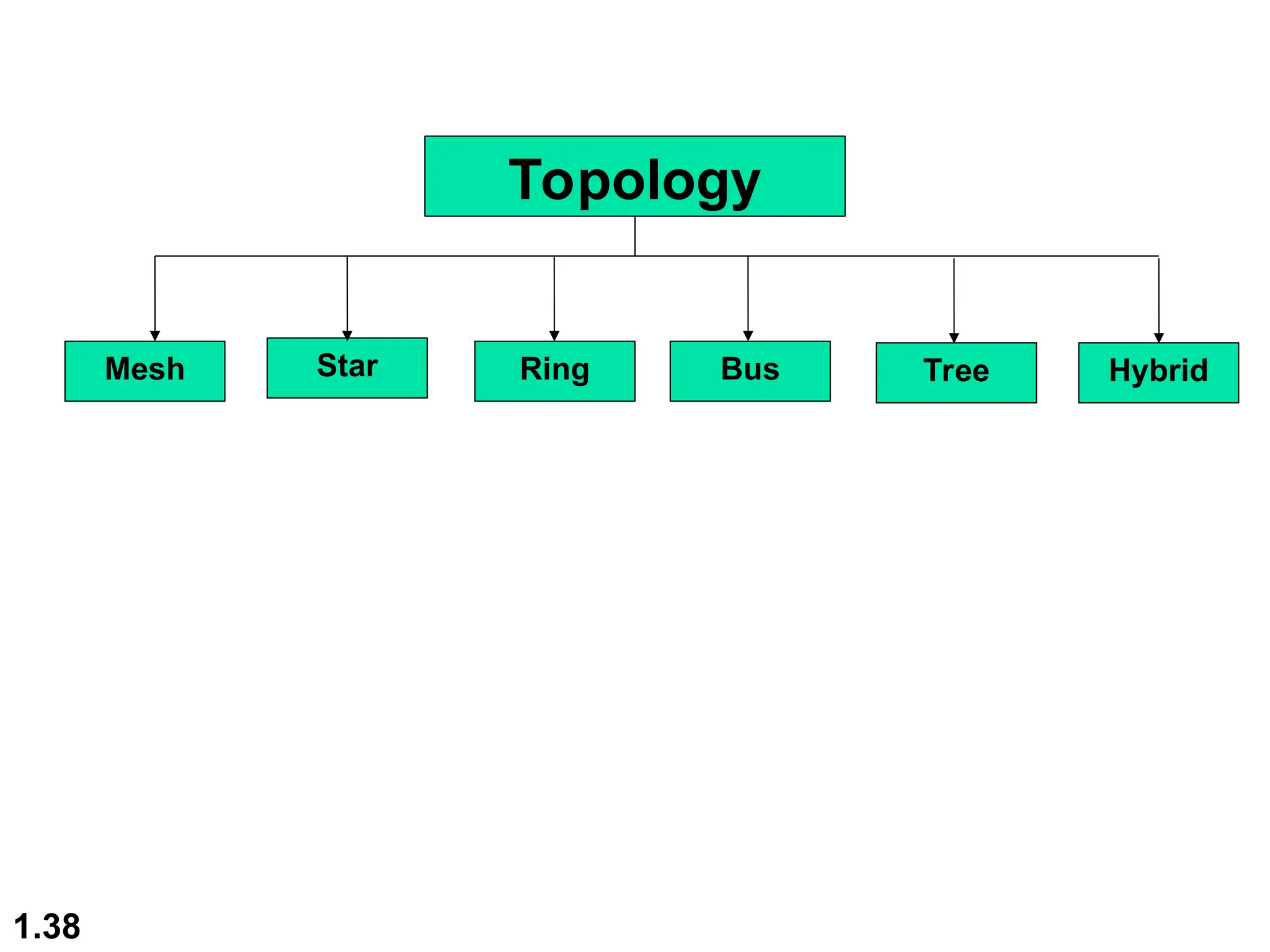
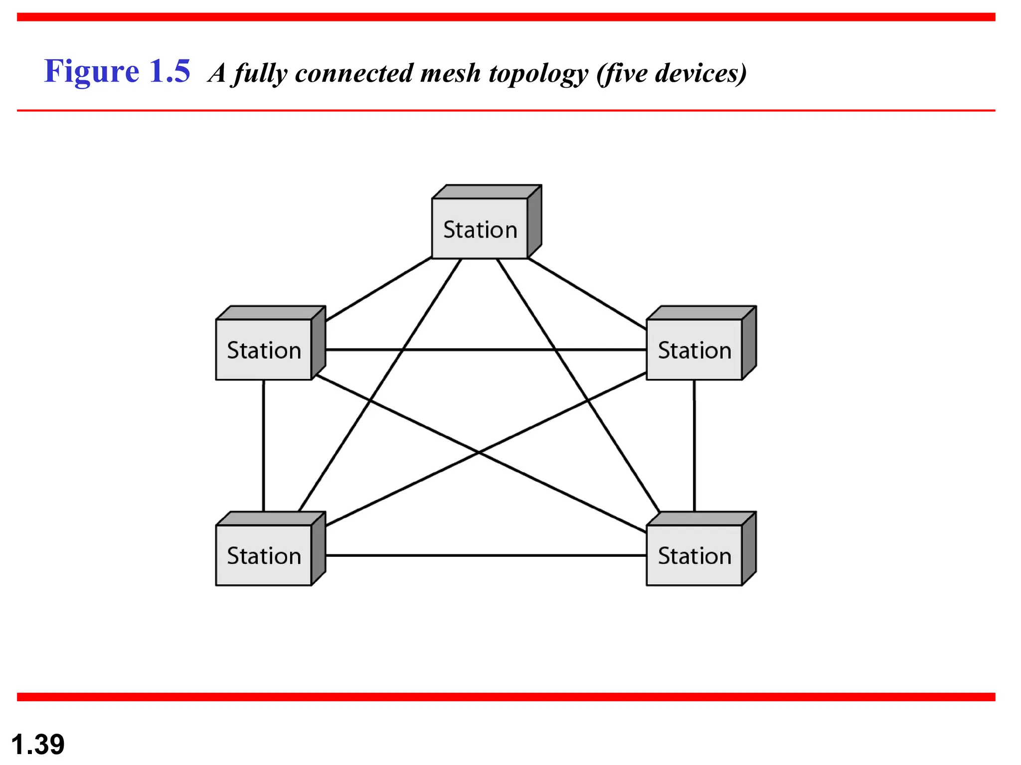
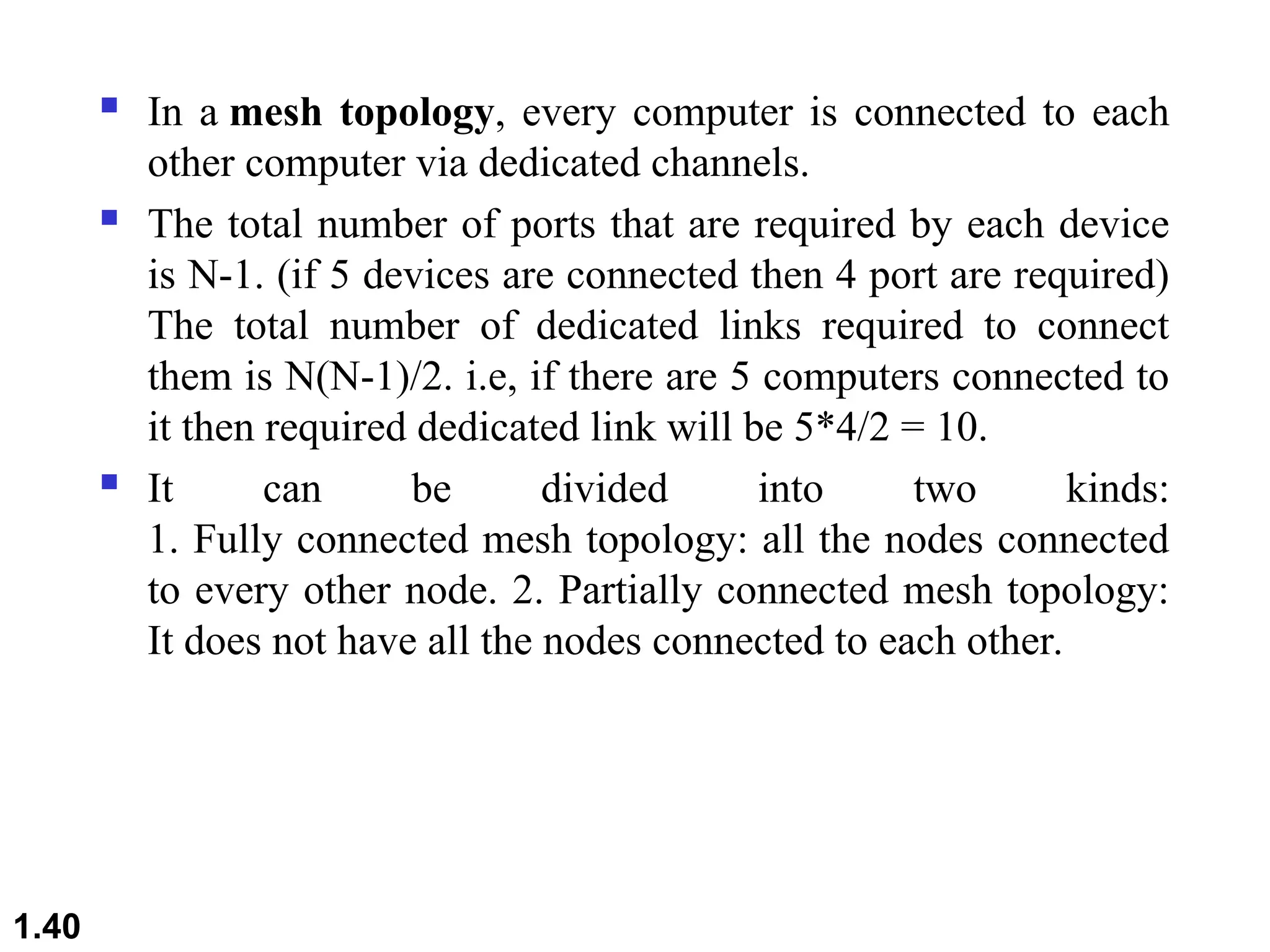
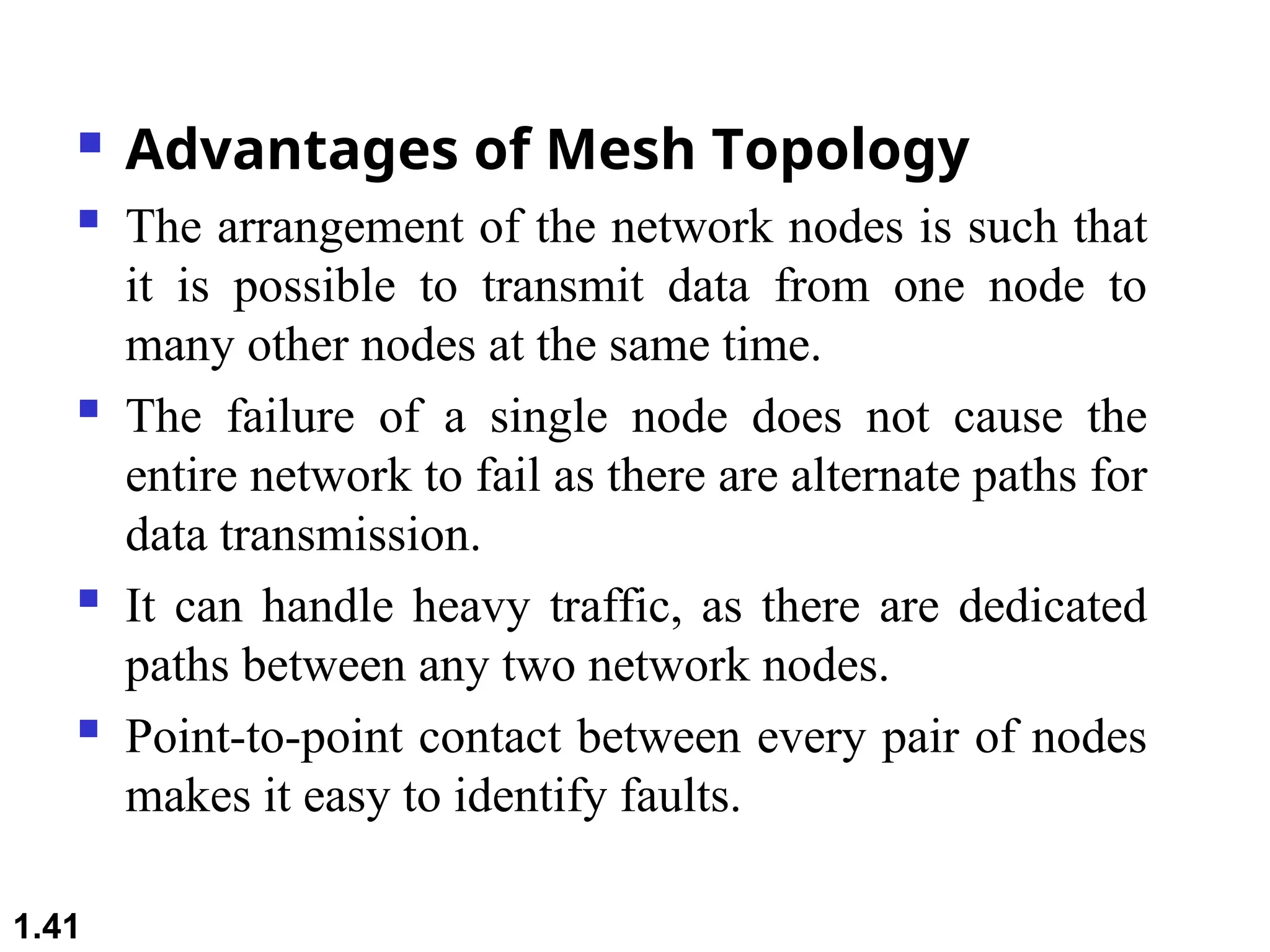
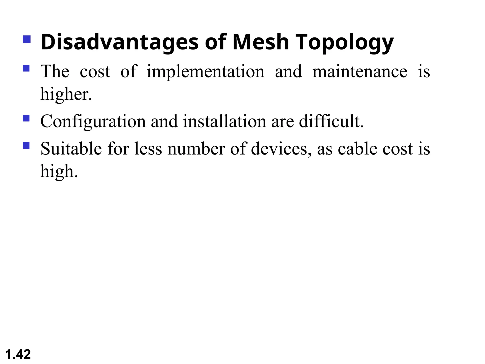
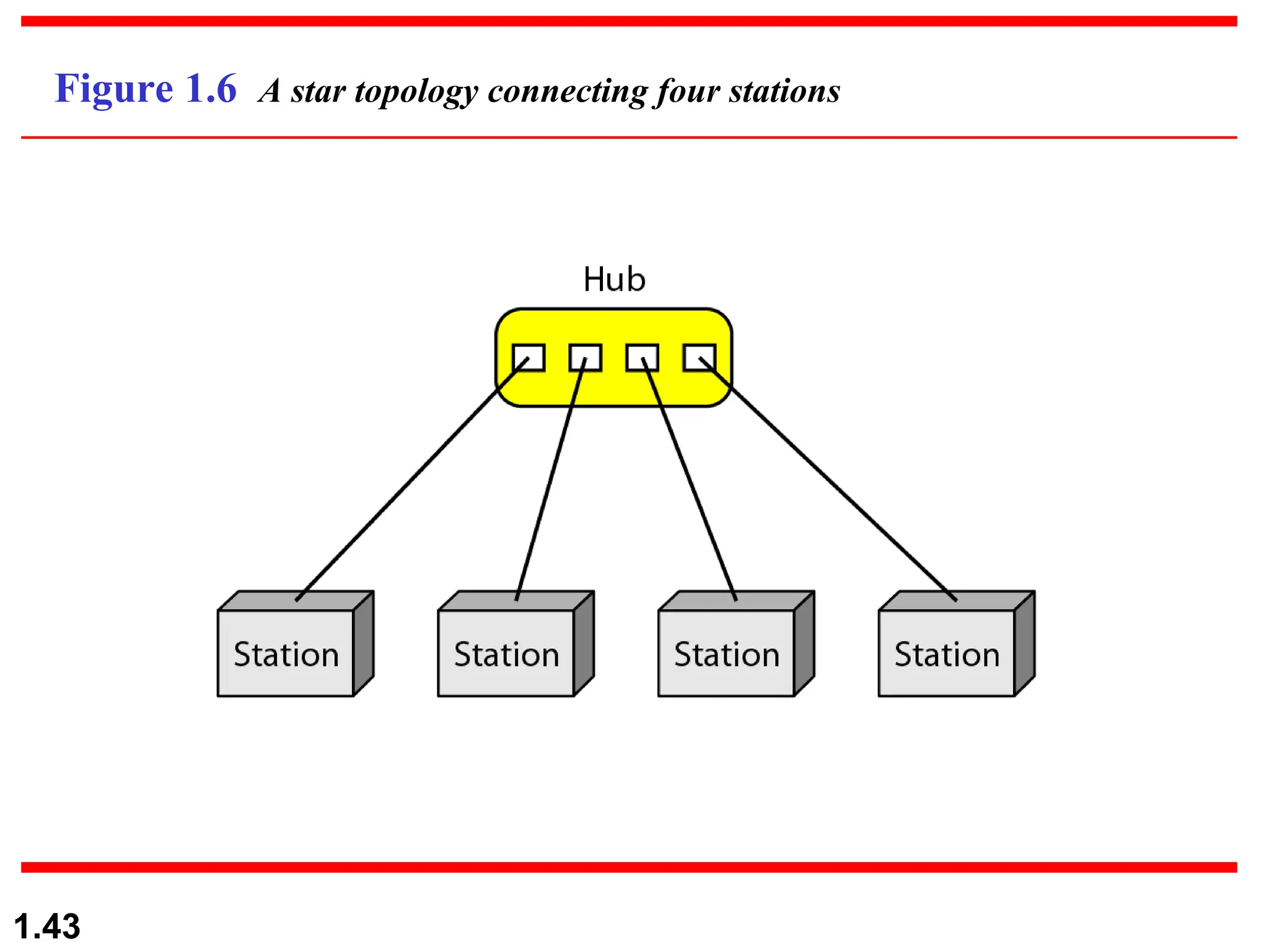
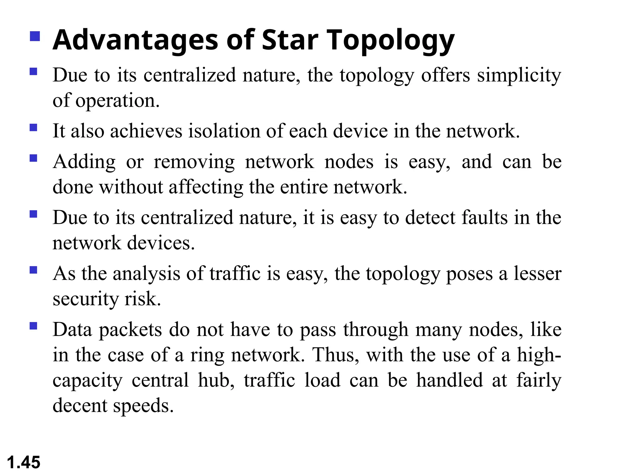
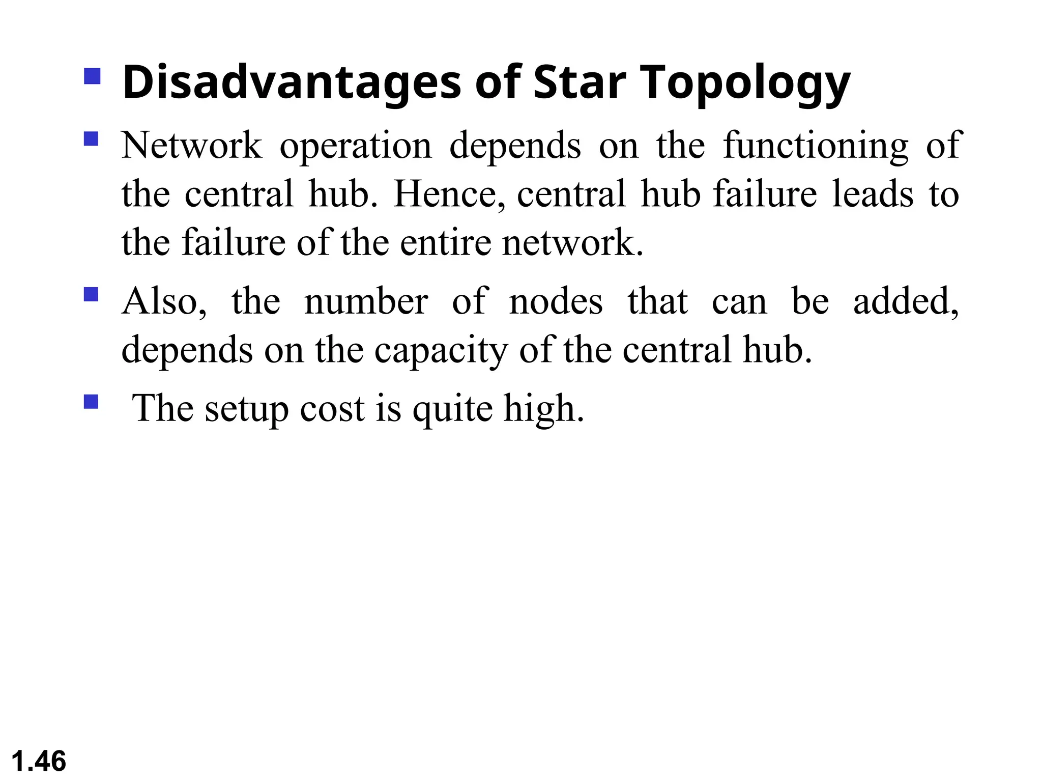
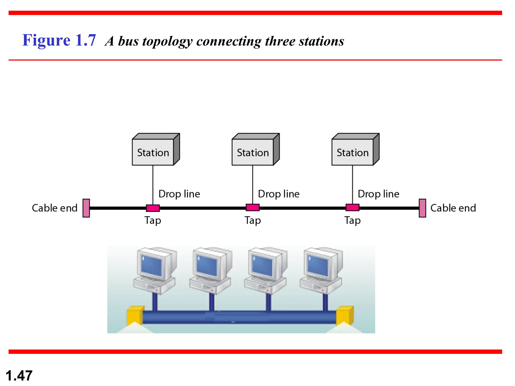
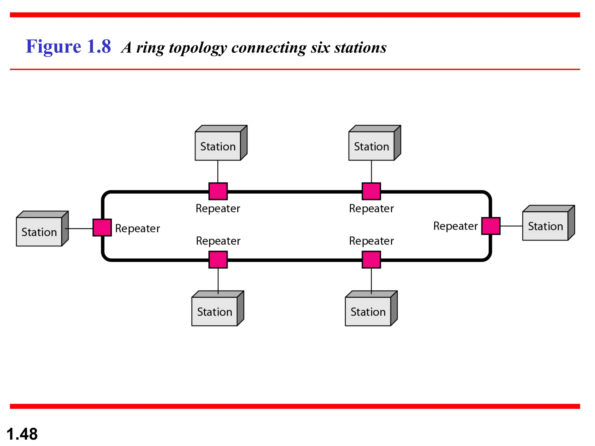
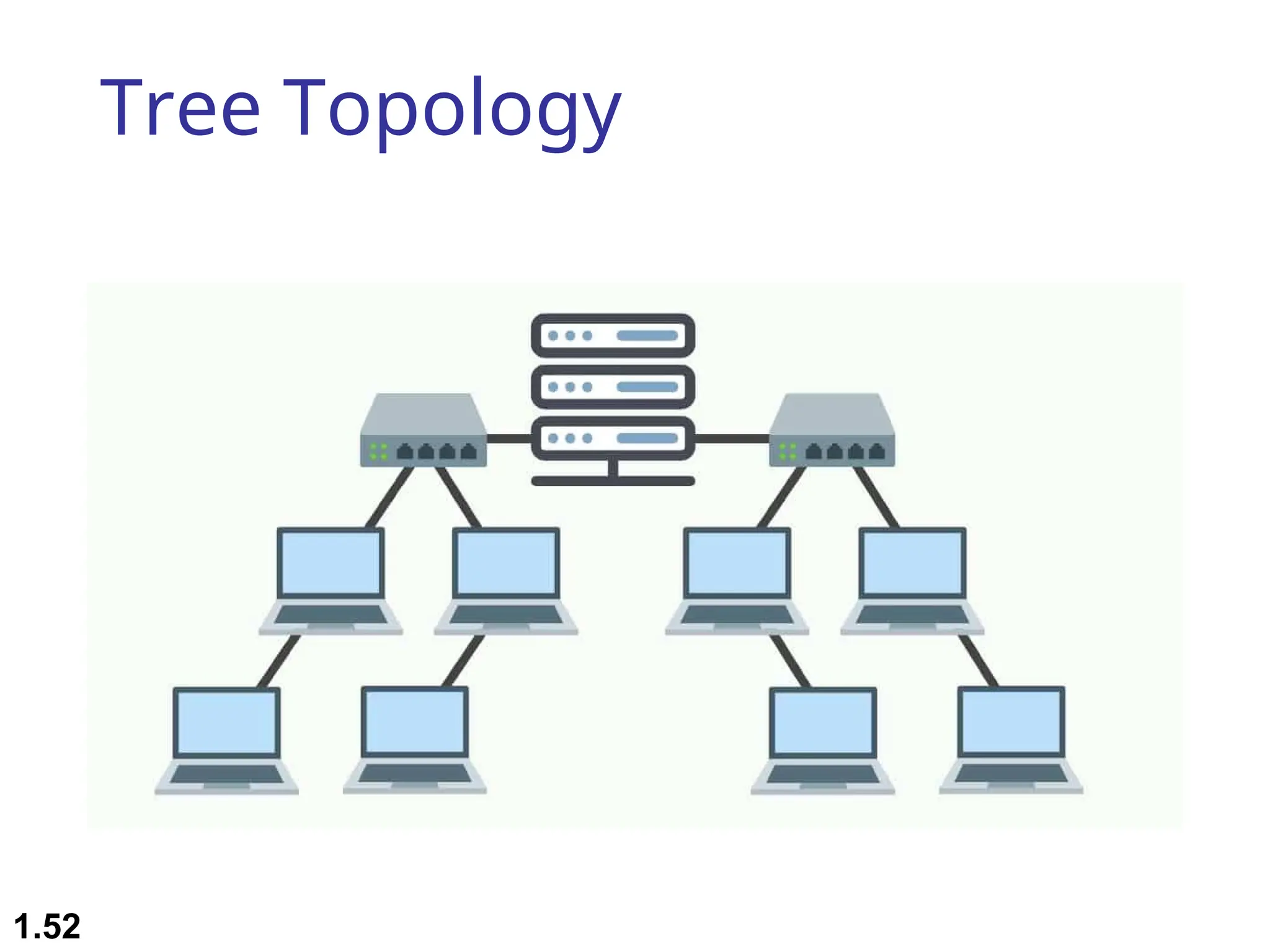
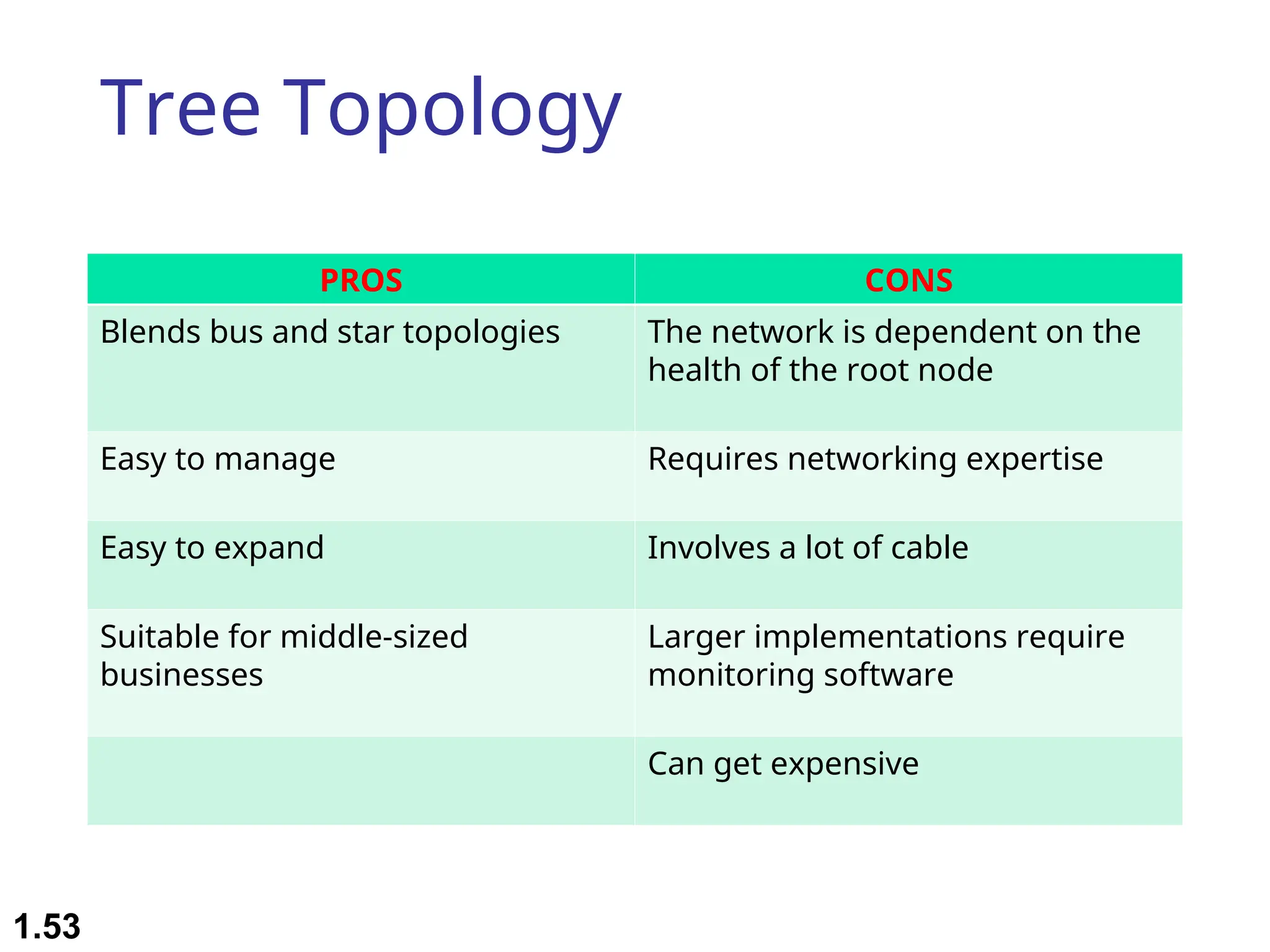
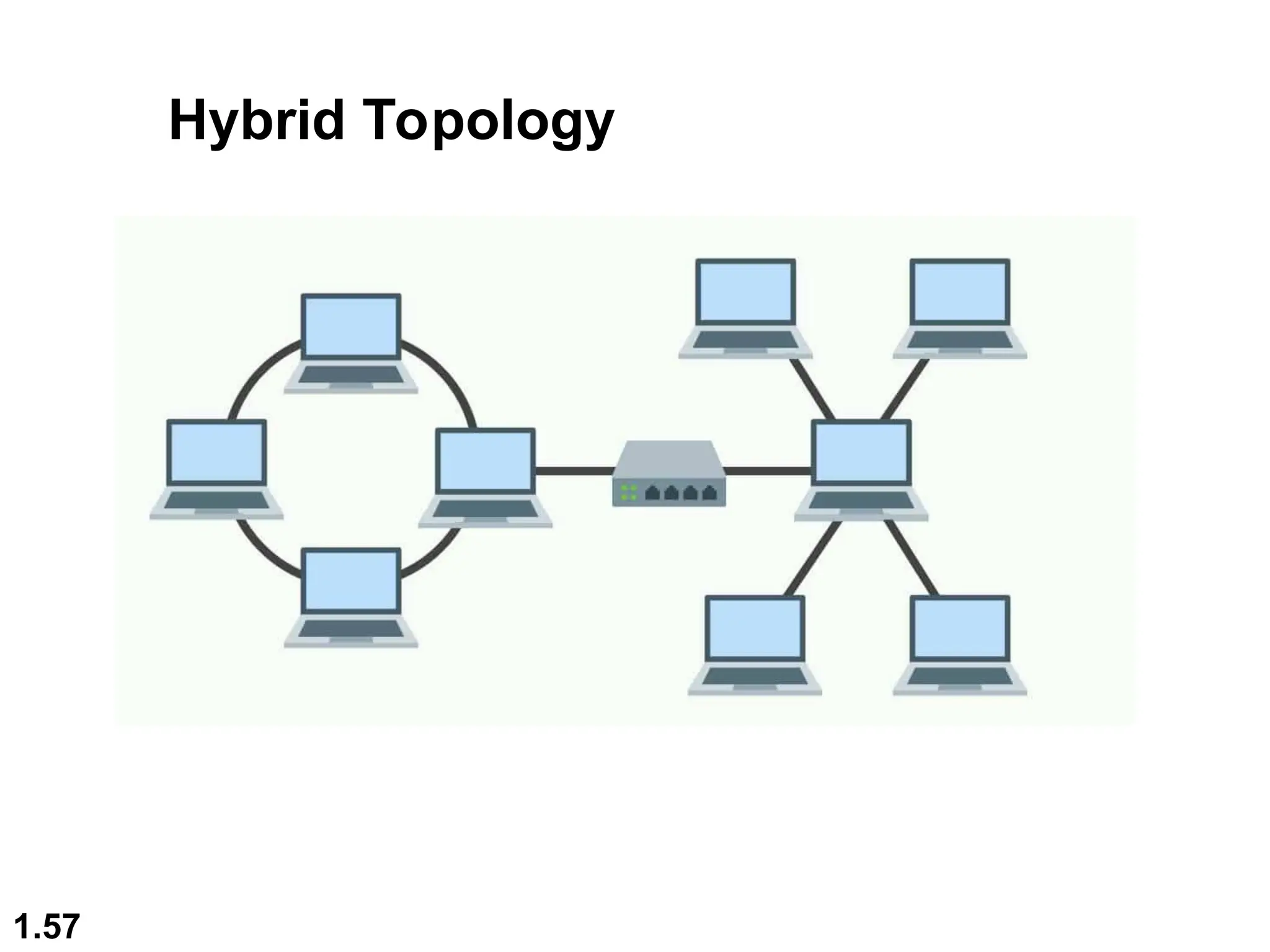
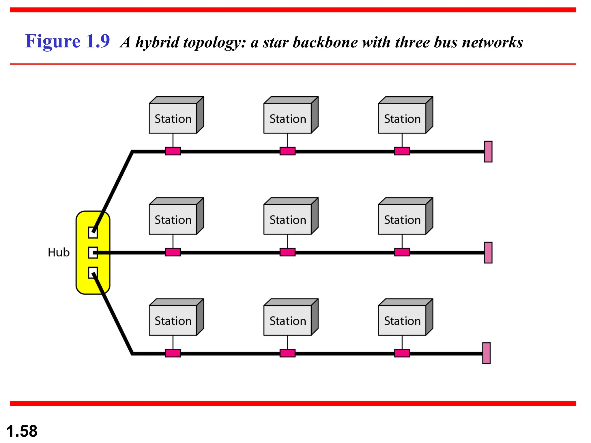
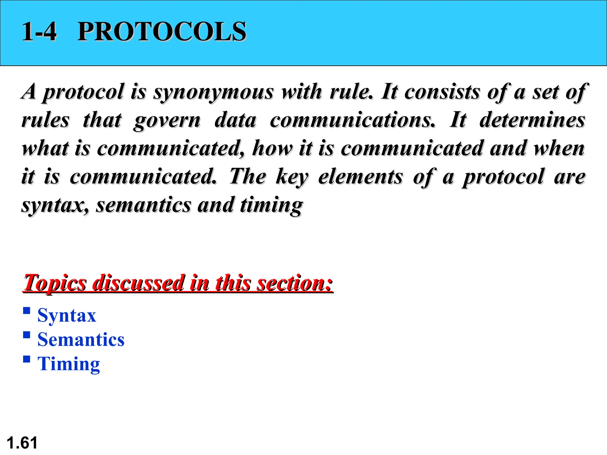
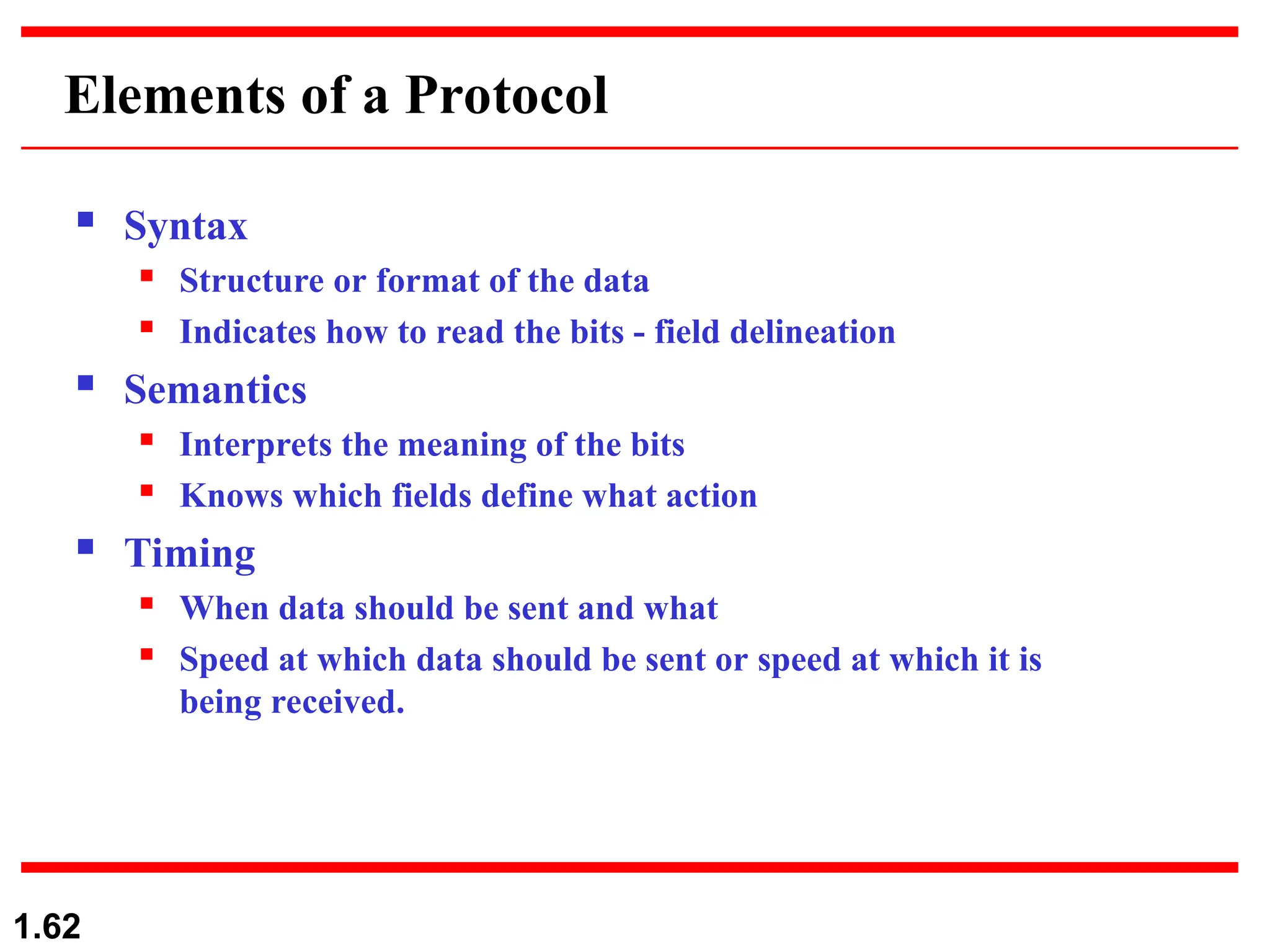
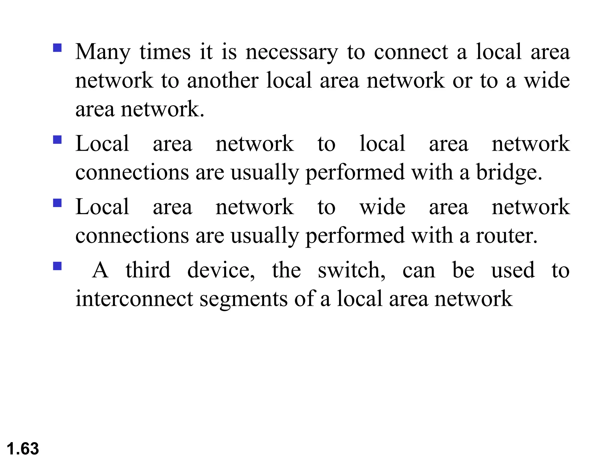
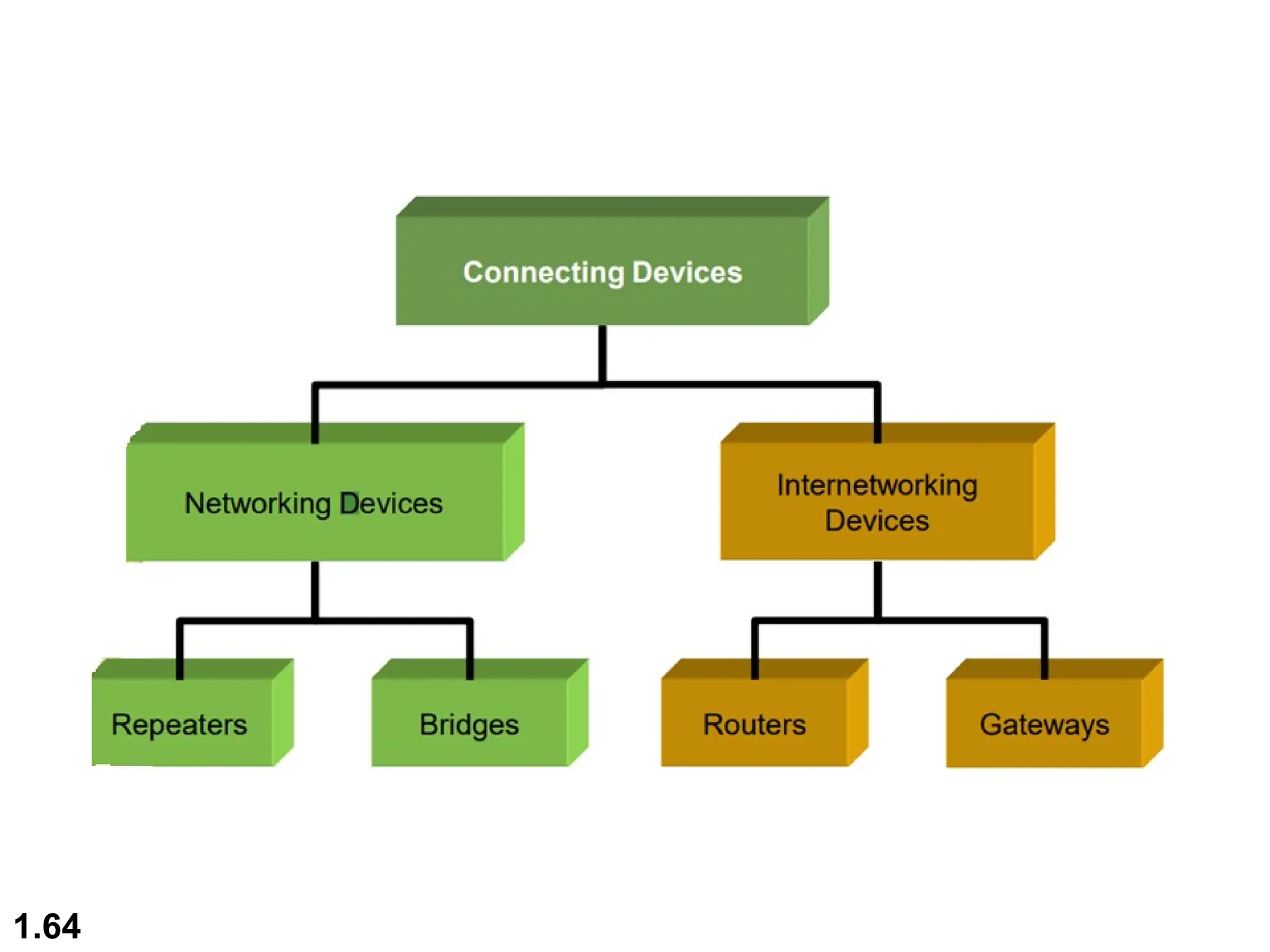
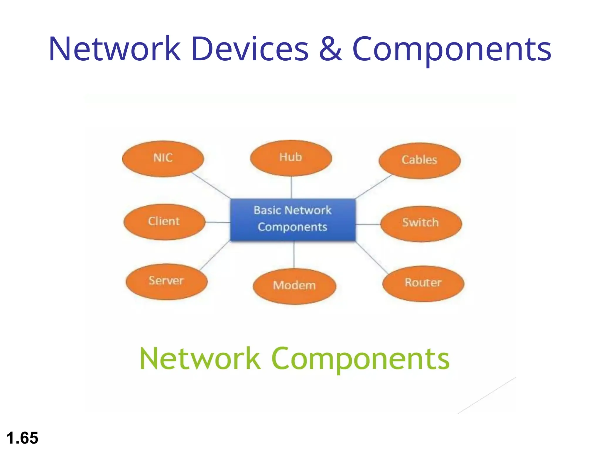
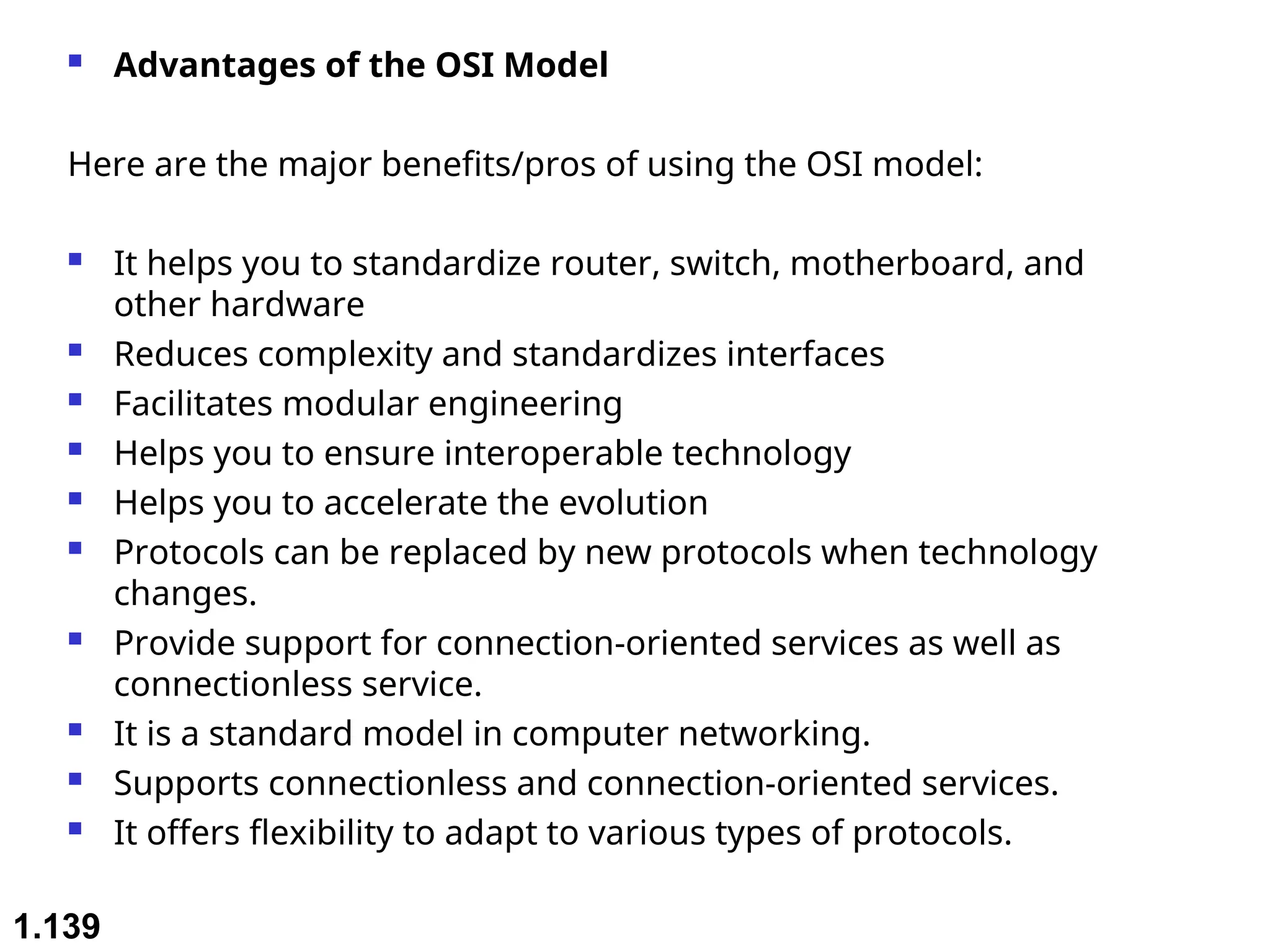
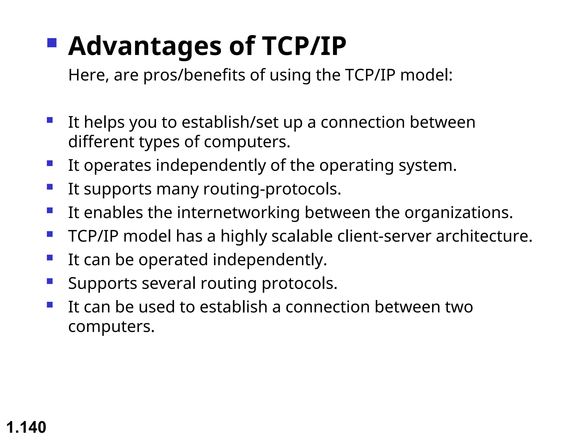
1.1
Chapter 1
Introduction
Copyright © The McGraw-Hill Companies, Inc. Permission required for reproduction or display.
1.2
 Examination Scheme (Theory)
 Term Test : 15 Marks
 Teacher Assessment : 20 Marks
 End Sem Exam : 65 Marks
 Total Marks : 100 Marks
 Examination Scheme (Practical)
 Teacher Assessment : 25 Marks
 End Sem Exam : 25 Marks
 Total Marks: 50 Marks
1.3
 Course Objectives:
 This course aims to provide students with a comprehensive
understanding of computer networks, from the fundamental
concepts of networking to advanced topics such as Internet
of Things (IoT) architecture and wireless networks.
 Students will explore the key components of networking,
including the network layer, transport and application layer
protocols, and the interconnection of smart objects using IP.
 By the end of the course, students will be equipped with
the knowledge and skills necessary to design, manage, and
troubleshoot computer networks, with a focus on emerging
technologies and applications in the field.
1.4
1.5
Unit-1 Contents
 Introduction to Computer Networks: Basics
of Computer Networks
 Network Topologies and Protocols
 OSI and TCP/IP Models
 Network Devices and Components.
1.6
1.7
1-1 DATA COMMUNICATIONS
The term
The term telecommunication
telecommunication means communication at a
means communication at a
distance. The word
distance. The word data
data refers to information presented
refers to information presented
in whatever form is agreed upon by the parties creating
and using the data.
and using the data. Data communications
Data communications are the
are the
exchange of data between two devices via some form of
transmission medium such as a wire cable.
 Components of a data communications system
 Data Flow
Topics discussed in this section:
1.8
A data communication system is made up of five
components
1. Message: the information (data) to be communicated
– Consist of text, numbers, pictures, audio, or video
2. Sender: the device that sends the data message
– Computer, workstation, telephone handset, video camera,
…
3. Receiver: the device that receives the message
– Computer, workstation, telephone handset, television
4. Medium: The physical path by which a message travels from
sender to receiver
– twisted pair, coaxial cable, fiber-optic, radio waves
5. Protocol: a set of rules that govern data communications
– An agreement between the communicating devices
– Devices may be connected but not communicating (no
protocol)
– Arabic speaker with Japanese speaker
1.9
Figure 1.1 Components of a data communication system
1.10
Data Flow
Communication between two devices can be:
• Simplex
• Half-Duplex
• Full-Duplex
1.11
Figure 1.2 Data flow (simplex, half-duplex, and full-duplex)
 Simplex (one way street)
 The communication is unidirectional
 Only one device on a link can transmit; the other can
only receive
 Use the entire capacity of the channel to send data
 Example: Keyboards, Monitors
1.12
 Half-Duplex (one-lane with two-directional traffic)
 Each station can both transmit and receive, but not at
the same time
 When one device is sending, the other can only
receive, and vice versa
 The entire capacity of a channel is taken over by the
transmitting device
 Example: Walkie-talkies
1.13

Full-Duplex (Duplex) (two-way street)
 Both stations can transmit and receive at same time
 Signals going in either direction sharing the capacity of
the link
 Sharing can occur in two ways:
 Link has two physically separate transmission paths
 One for sending and the other for receiving
 The capacity of the channel is divided between signals
travelling in both directions
 Example: Telephone network
1.14
1.15
1-2 NETWORKS
1-2 NETWORKS
A
A network
network is a set of devices (often referred to as
is a set of devices (often referred to as nodes
nodes)
)
connected by communication
connected by communication links
links. A node can be a
. A node can be a
computer, printer, or any other device capable of sending
and/or receiving data generated by other nodes on the
network. A link can be a cable, air, optical fiber, or any
medium which can transport a signal carrying
information.
information.
 Network Criteria
 Physical Structures
 Categories of Networks
Topics discussed in this section:
1.16
Network Criteria
 Performance
 Depends on Network Elements
 Measured in terms of Delay(low) and Throughput( (high): a
measure of how fast we can actually send data through a network)
 Reliability
 Failure rate of network components
 Recovery time of a network after a failure
 Network’s robustness in a catastrophe: protect by good back up
network system
 Measured in terms of availability/robustness
 Security
 Data protection against corruption/loss of data due to:
 Errors
 Malicious users
 Physical Structures:
 Type of connection

Network: Two or more devices connected through
links

Link: Communication pathway that transfers data
from one device two another

Two devices must be connected in some way to the
same link at the same time. Two possible types:
 Point-to-Point
 Multipoint
1.17
1.18
Physical Structures
 Type of Connection
 Point to Point - single transmitter and receiver
 Dedicated link between two devices
 Entire capacity of the link is reserved for transmission between
those two devices
 Use an actual length of wire or cable
 Other options, such as microwave or satellite is possible
 Example: Television remote control
 Multipoint (Multidrop)- multiple recipients of single transmission
 More than two devices share a single link
 Capacity is shared
 Channel is shared either spatially or temporally
 Spatially shared: if devices use link at same time
 Timeshare: if users must take turns
1.19
1.20
Figure 1.3 Types of connections: point-to-point and multipoint
1.21
Categories of Networks
 Local Area Networks (LANs)
 Short distances
 Designed to provide local interconnectivity
 Wide Area Networks (WANs)
 Long distances
 Provide connectivity over large areas
 Metropolitan Area Networks (MANs)
 Provide connectivity over areas such as a city, a campus
1.22
Categories of Networks
Network Category depends on its size
Three primary categories
LAN
LAN: Covers area < 2miles
WAN
WAN: Can be worldwide
MAN
MAN: Between LAN & WAN, span 10s of
miles
Local Area Network (LAN)
 Privately owned
 Links devices in the same office, building, or
campus
 Simple LAN: 2 PCs & 1 printer in home or office
 Size is limited to a few kilometers
 Allow resources to be shared (hardware, software,
or data)
1.23
Local Area Network (LAN)
1.24
An isolated LAN connecting 12 computers to a hub in a closet
Local Area Network (LAN)
 LAN is distinguished by:
 Size (# users of OS, or licensing restrictions)
 Transmission medium (only one type)
 Topology (bus, ring, star)
 Data Rates (speed):
 Early: 4 to 16 Mbps
 Today: 100 to 1000 Mbps
1.25
Wide Area Networks (WAN)
 Provides long-distance transmission of data
over large geographic areas (country,
continent, world)
1.26
Wide Area Networks (WAN)
 Switched WAN
 Backbone of the Internet
 Dialup line point-to-point WAN
 Leased line from a telephone company
1.27
Wide Area Networks (WAN)
1.28
Metropolitan Area Networks (MAN)
 Size between LAN and WAN
 Inside a town or a city
 Example: the part of the telephone company
network that can provide a high-speed DSL
to the customer
1.29
Metropolitan Area Networks (MAN)
 Two or more networks connected together
1.30
1.31
Figure 1.12 A heterogeneous network made of four WANs and two LANs
The Internet
 Internet has revolutionized many aspects of our daily lives.
 It has affected the way we do business as well as the way
we spend our leisure time.
 Internet is a communication system that has brought a
wealth of information to our fingertips and organized it for
our use
 An internet is 2 or more networks that can communicate
with each other
 The Internet is a collaboration of more than hundreds of
thousands of interconnected networks
1.32
1.33
Figure 1.13 Hierarchical organization of the Internet
Protocols and Standards
 Protocol synonymous with rule
 Standards: agreed-upon rules
 Protocols
 A protocol is a set of rules that govern data
communications
 Defines What, How, and When it is communicated
1.34
Protocols and Standards
 Elements of a protocol:
 Syntax: structure or format of data

Example: 8-bits address of sender, 8-bits address of receiver,
remaining bits: message stream
 Semantics: meaning of each section of bits. It refers
when data sent and how fast it is sent

Example: Does the address is a route to be taken or the
final destination of the message
 Timing: when data should be sent and how fast they can
be sent

Example: sender produces data at 100 Mbps but the
receiver can process data at only 1 Mbps  overload
and data loose
1.35
1.36
Physical Topology
 Connection of devices
 The way a network is laid out physically
 Two or more links form a topology
 The topology of a network is the geometric
representation of the relationship of all the links and
linking devices (nodes) to one another.
 Four topologies : Mesh, Star, Bus, and Ring
• Type of transmission - unicast, mulitcast, broadcast
1.37
Figure 1.4 Categories of topology
1.38
Topology
Mesh Star Ring Bus Tree Hybrid
1.39
Figure 1.5 A fully connected mesh topology (five devices)
 In a mesh topology, every computer is connected to each
other computer via dedicated channels.
 The total number of ports that are required by each device
is N-1. (if 5 devices are connected then 4 port are required)
The total number of dedicated links required to connect
them is N(N-1)/2. i.e, if there are 5 computers connected to
it then required dedicated link will be 5*4/2 = 10.
 It can be divided into two kinds:
1. Fully connected mesh topology: all the nodes connected
to every other node. 2. Partially connected mesh topology:
It does not have all the nodes connected to each other.
1.40
 Advantages of Mesh Topology
 The arrangement of the network nodes is such that
it is possible to transmit data from one node to
many other nodes at the same time.
 The failure of a single node does not cause the
entire network to fail as there are alternate paths for
data transmission.
 It can handle heavy traffic, as there are dedicated
paths between any two network nodes.
 Point-to-point contact between every pair of nodes
makes it easy to identify faults.
1.41
 Disadvantages of Mesh Topology
 The cost of implementation and maintenance is
higher.
 Configuration and installation are difficult.
 Suitable for less number of devices, as cable cost is
high.
1.42
1.43
Figure 1.6 A star topology connecting four stations
 In star topology, all the computers are connected
to a single central node called a hub through a
cable. All the transmission of data is through the
hub.
 Every computer is connected to the hub through a
dedicated connection/cable.
 Hub also acts as a repeater.
 The performance of the network depends on the
capacity of central Hub . If the hub has high data
transfer rate , the overall network performance is
likely to be good
1.44
 Advantages of Star Topology
 Due to its centralized nature, the topology offers simplicity
of operation.
 It also achieves isolation of each device in the network.
 Adding or removing network nodes is easy, and can be
done without affecting the entire network.
 Due to its centralized nature, it is easy to detect faults in the
network devices.
 As the analysis of traffic is easy, the topology poses a lesser
security risk.
 Data packets do not have to pass through many nodes, like
in the case of a ring network. Thus, with the use of a high-
capacity central hub, traffic load can be handled at fairly
decent speeds.
1.45
 Disadvantages of Star Topology
 Network operation depends on the functioning of
the central hub. Hence, central hub failure leads to
the failure of the entire network.
 Also, the number of nodes that can be added,
depends on the capacity of the central hub.
 The setup cost is quite high.
1.46
1.47
Figure 1.7 A bus topology connecting three stations
1.48
Figure 1.8 A ring topology connecting six stations
1.49
In a Ring topology, the device forms the ring shape, in
which each device is connected exactly to its neighbour
on both sides through point to point connection and the
first and last nodes are connected to each other.
The functionality of Ring topology:
1.In this topology, one device known as monitor station
will take responsibility for the operation.
2.Station has to hold the token to transmit the data.
3.When no station is holding the token then the token
will be circulated in the ring
1.50
1.To prevent the loss of the transmission data from the first node
to the last node say i.e,1000th node, number of repeaters are
deployed in the network.
2.Dual Ring Topology: Bidirectional connections between each
network node.
3.Data is transmitted in a sequential manner it can’t skip device
in between.
Disadvantages of Ring topology
•Difficult to troubleshoot.
•Failure in a single computer can lead to disturbing the whole
network.
•Adding or removing a computer will disturb the transmission of
the data in the network.
 Advantages of Ring Topology
 The data being transmitted between two nodes passes
through all the intermediate nodes. A central server is not
required for the management of this topology.
 The traffic is unidirectional and the data transmission is
high-speed.
 In comparison to a bus, a ring is better at handling load.
 The adding or removing of network nodes is easy, as the
process requires changing only two connections.
 The configuration makes it easy to identify faults in
network nodes.
 In this topology, each node has the opportunity to transmit
data. Thus, it is a very organized network topology.
 It is less costly than a star topology.
1.51
Tree Topology
1.52
Tree Topology
PROS CONS
Blends bus and star topologies The network is dependent on the
health of the root node
Easy to manage Requires networking expertise
Easy to expand Involves a lot of cable
Suitable for middle-sized
businesses
Larger implementations require
monitoring software
Can get expensive
1.53
Tree Topology
 Imagine a hierarchy of network nodes, with the root node
serving client nodes, that in turn serve other lower-level
nodes.
 The top-level node is mostly a mainframe computer while
other nodes in the hierarchy are mini or microcomputers.
 In this arrangement, the node at each level could be forming
a star network with the nodes it serves. In this case, the
structure combines star and bus topologies and inherits their
advantages and disadvantages.
 Tree topology is used to organised the computers in
corporate network.
1.54
 Advantages of Tree Topology
 The tree topology is useful in cases where a star or bus
cannot be implemented individually. It is most suited in
networking multiple departments of a university or
corporation, where each unit (star segment) functions
separately and is also connected with the main node (root
node).
 The advantages of centralization that are achieved in a star
topology are inherited by the individual star segments in a
tree network.
 Each star segment gets a dedicated link from the central
bus. Thus, the failure of one segment does not affect the
rest of the network.
 Fault identification is easy.
 The network can be expanded by the addition of secondary
nodes. Thus, scalability is achieved.
1.55
 Disadvantages of Tree Topology
 As multiple segments are connected to a central bus, the
network depends heavily on the bus. Its failure affects the
entire network.
 Owing to its size and complexity, maintenance is not easy
and costs are high. Also, configuration is difficult in
comparison to that in other topologies.
 Though it is scalable, the number of nodes that can be
added depends on the capacity of the central bus and on the
cable type.
1.56
1.57
Hybrid Topology
1.58
Figure 1.9 A hybrid topology: a star backbone with three bus networks
 A hybrid topology is a combination of two or more types
of network topology.
This types of network topology are usually implemented by
the organisation
 Examples of Hybrid Topology
 Internet is the best example of the largest Hybrid topology
If there is a bus topology in the IT department while ring
topology in the HR department then connecting these two
will result in the hybrid topology.
 Features of Hybrid Topology
 1. Collection of two or more topology.
1.59
 Advantages of Hybrid Topology
 Scalable: easy to increase the size of the network by adding
new components
 Effective: design in such a way that the strength of
constituent topologies is maximized.
 Flexible: It can be designed according to the requirement of
the organisation.
 Reliable: as troubleshooting is easy and Error detecting.
fault detection and troubleshooting
 Disadvantages of Hybrid Topology
 Costly to implement: Cost of Infrastructure, hub and
expertise increases.
 Difficult to manage as it is complex in design.
1.60
1.61
1-4 PROTOCOLS
1-4 PROTOCOLS
A protocol is synonymous with rule. It consists of a set of
rules that govern data communications. It determines
what is communicated, how it is communicated and when
it is communicated. The key elements of a protocol are
syntax, semantics and timing
 Syntax
 Semantics
 Timing
Topics discussed in this section:
1.62
Elements of a Protocol
 Syntax
 Structure or format of the data
 Indicates how to read the bits - field delineation
 Semantics
 Interprets the meaning of the bits
 Knows which fields define what action
 Timing
 When data should be sent and what
 Speed at which data should be sent or speed at which it is
being received.
 Many times it is necessary to connect a local area
network to another local area network or to a wide
area network.
 Local area network to local area network
connections are usually performed with a bridge.
 Local area network to wide area network
connections are usually performed with a router.
 A third device, the switch, can be used to
interconnect segments of a local area network
1.63
1.64
Network Devices & Components
1.65
1.66
Network Devices & Components
 Network Devices:
 Are products used to expand or connect
networks
 Can control the amount of traffic on a
network
 Can speed up the flow of data over a
network
1.67
Network Interface card(NIC)
 NIC provides the physical interface between
computer and cabling
 It prepares data, sends data, and controls the
flow of data.It can also receive and translate
data into bytes for the CPU to understand
1.68
1.69
Repeater
 A repeater is a regenerator, not an amplifier A repeater
installed on a link receives the signal before it becomes too
weak or corrupted , regenerates the original bit pattern, and
put the refreshed copy back onto the link.
1.70
 Repeaters are very small devices . They allow a cabling
system to extend beyond its maximum allowed length by
amplifying the network voltage so they travel farther
 Repeaters are nothing more than amplifiers and as such are
very inexpensive . Repeaters can only be used to regenerate
signals between similar network segments
 The main disadvantage to repeater is that they just amplify
signals. These signals not only include network signals, but
any noise on the wire as well.
1.71
Hub
 A device that connects all the computers in a network to
each other.
 Hub is a common connection point for devices in a network
 A hub contains multiple ports. When a packet arrives at one
port , it is copied to the other ports so that all segments of
the LAN can see all the packets
1.72
Hub
1.73
Switch
1.74
Switch
 A network switch is a computer networking device that
connects network segments
 Low end network switches appear nearly identical to
network hubs , but a switch contains more
“intelligence”(and slightly higher price) than a network hub
 Switch is data link layer device.
 Switch can perform error checking before forwarding data,
that makes it very efficient as it does not forward packets
that have errors and forward good packets selectively to
correct port only
 Network switches are capable of inspecting data packets as
they are received, determining the source and destination
device of that packet , and forwarding it appropriately
1.75
 A vital difference between hub and switch is that all the
nodes connected to a hub share the bandwidth among
themselves, while a device connected to a switch port has
the full bandwidth all to itself
 For ex. If 10 nodes are communicating using a hub on 10-
Mbps network, then each node may only get a portion of
the 10 Mbps if other nodes on the hub want to communicate
as well. But with a switch , each node could possibly
communicate at the full 10 Mbps
1.76
Switch
1.77
Router
 A router is a device like a switch that routes data
packets based on their IP addresses.
 Router is mainly a Network Layer device.
 Routers normally connect LANs and WANs
together and have a dynamically updating routing
table based on which they make decisions on
routing the data packets.
 Like bridges, they can segment large networks and
can filter out noise.
 Highly intelligent device and more expensive that
connect multiple network types and determine the
best path for sending data
1.78
Routers
1.79
Bridge
Bridge
S1 S2
S4
S3
S5 S6
LAN1
LAN2
1.80
Bridges
 As a physical layer device , it regenerates the signal it receives
 As a data link layer device the Bridge can check the
Physical/MAC address (source & destination) contained in the
frame
 Bridges use backward learning in recording source address on
transmissions.
 Unlike repeaters, bridges will not forward a frame onto another
LAN segment if it knows about the location of the destination
node.
 Bridge management gets more complicated when loops are
possible in the frame route.
 It can connect on different architectures like Ethernet and Token-
ring
 It provide packet filtering , meaning it only passes the packet that
are allow on destination network
1.81
1.82
How it works?
 Bridge examine each packet as it enters through
one of the port, it first checks MAC address of the
sender and create a mapping between the port and
the sender MAC address .
 Then it looks MAC address of destination and
compare the list of all learned MAC addresses.
 If the address is in the list then bridge look up the
port number & forward the packet to the port
where the destination is connected .
 If the destination’s MAC address is not in the list
the bridge blocks the data from passing
1.83
1.84
Gateway
 A gateway is a protocol convertor.
 It accepts a packet format for one protocol(e.g.,
Apple Talk) and converts it into a packet format for
another protocol(e.g.,TCP/IP).
 It is a computer that operates in all 5 layer or 7 layers
of OSI model
 A Gateway takes an application message, reads it &
interprets it
 In homes, the Gateway is the ISP(internet service
provider) that connects the user to the Internet.
1.85
Gateway
1.86
MAC Address
 A Media Access Control (MAC) address is a 48-bit address
that is used for communication between 2 hosts in an
Ethernet environment
 It is a hardware address which means that it is stored in the
firmware of the network card
 A MAC address is supposed to be globally unique. Each
network card vendor gets its share of addresses (represented
by the first 24 bits)

The address is written in the form of 12 hexadecimal digits.
 Ex. D8-D3-85-EB-12-E3
 Every hexadecimal character represents 4 bits so the first 6
hexadecimal characters represent the vendor(in this case
Hewlett Packard)
 It is a physical address
1.87
1.88
IP Address
 An IP address is a 32 bit number that identifies a host on a
network. It is usually written in the form of 4 decimal
numbers separated by periods (ex.10.0.50.1)
 An IP address is a logical address
 Any device that wants to communicate with other device
using TCP/IP needs to have an IP address . It can be
configured manually or it can be obtained from a DHCP
server
 The term “IP address” is used for IPV4 which is the fourth
version of the IP protocol.
 A newer version exists IPV6 that uses 128 bit addressing
1.89
Protocol Architecture
 It is layered structure of H/W and S/W that
supports exchange of data between systems
 It supports distributed applications(E-mail , file
transfer)
 Each layer of protocol architecture provides some
set of rules
 There are 2 widely used protocol architecture
 OSI Model
 TCP/IP architecture
1.90
OSI Model
 An ISO(International standard organization) that covers all
aspects of network communications is the open system
Interconnection (OSI) model
 An open system is a model that allows any 2 different
systems to communicate regardless of their underlying
architecture(H/w and S/w)
 The OSI model is not a protocol ; it is a model for
understanding and designing a network architecture that is
flexible, robust and interoperable
 The OSI model is a layered framework for the design of
network systems that allows for communication across all
types of computer systems
1.91
 The purpose of the OSI model is to facilitate
communication between different systems(2
different OS) without requiring changes to the
logic of the underlying hardware & software
1.92
 The OSI model is built of 7 ordered layers
1. (layer 1) physical layer
2. (layer 2) Data Link layer
3. (layer 3) Network layer
4. (layer 4) Transport layer
5. (layer 5)Session layer
6. (layer 6) Pesentation layer
7. (layer 7) Application layer
1.93
1.94
Peer to Peer Process
 Within a single machine each layer calls upon the
services of the layer just below it
 Layer 3, for example , uses the services provided
by layer 2 and provides services for layer 4
 Between machines, layer x on one machine
communicates with layer x on another machine , by
using a protocol (this is peer-to –peer process)
 Communication between machines is therefore
peer to peer process using protocols appropriate to
a given layer
1.95
1.96
1.97
1.98
1.99
1.100
1.101
1.102
1.103
1.104
1.105
1.106
1.107
1.108
1.109
1.110
1.111
1.112
1.113
1.114
1.115
1.116
 Helps in setting up & managing connections , enabling
sending & receiving of data followed by termination of
connections or sessions
 Seesion layer has it own helpers called APIs which allows
applications on different computers to communicate with each
other
 Just before a connection or session established with the server ,
server perform a function called Authentication (process of
verifying “who you are?”) for this server uses username &
password. Once entered username & password are matched a
seesion or connection is established between your computer &
server.
 Authrization is checked afterwards. If you have permission to
access a file?
 Session layer keeps the track of files that are being
downloaded
 Helps in session management. (which data packet belong to
which file(eg. text or image file) & tracks where the received
data packet go
1.117
1.118
1.119
1.120
1.121
1.122
1.123
1.124
TCP/IP
 A network model designed to support network communication even if the
computers are from different manufacturers
 It is specifically designed as a model to offer highly reliable and end-to-end
byte stream over an unreliable internetwork.
 As per the name TCP/IP seems to be a set of 2 protocols only, however it
consists of numerous protocols bundled at different layers.
 Application layer generates the message which pass through the lower layer
at the sending node where each layer encapsulates the message from the
above layer . So the message sent becomes larger & larger as it passes down
the chain
 TCP/IP helps you to determine how a specific computer should be
connected to the internet and how you can transmit data between them. It
helps you to create a virtual network when multiple computer networks are
connected together.
1.125
1.126
1.127
1.128
1.129
1.130
1.131
1.132
Physical Layer
1.133
1.134
Media Access Control(MAC
sublayer)
1.135
1.136
1.137
The remaining layers are
implemented in the form of software
programs in computer’s operating
system
1.138
 Advantages of the OSI Model
Here are the major benefits/pros of using the OSI model:
 It helps you to standardize router, switch, motherboard, and
other hardware
 Reduces complexity and standardizes interfaces
 Facilitates modular engineering
 Helps you to ensure interoperable technology
 Helps you to accelerate the evolution
 Protocols can be replaced by new protocols when technology
changes.
 Provide support for connection-oriented services as well as
connectionless service.
 It is a standard model in computer networking.
 Supports connectionless and connection-oriented services.
 It offers flexibility to adapt to various types of protocols.
1.139
 Advantages of TCP/IP
Here, are pros/benefits of using the TCP/IP model:
 It helps you to establish/set up a connection between
different types of computers.
 It operates independently of the operating system.
 It supports many routing-protocols.
 It enables the internetworking between the organizations.
 TCP/IP model has a highly scalable client-server architecture.
 It can be operated independently.
 Supports several routing protocols.
 It can be used to establish a connection between two
computers.
1.140

Unit-1 _weqeqeqweqweqweweqweqweqwweCCN.ppt

  • 1.
    1.1 Chapter 1 Introduction Copyright ©The McGraw-Hill Companies, Inc. Permission required for reproduction or display.
  • 2.
  • 3.
     Examination Scheme(Theory)  Term Test : 15 Marks  Teacher Assessment : 20 Marks  End Sem Exam : 65 Marks  Total Marks : 100 Marks  Examination Scheme (Practical)  Teacher Assessment : 25 Marks  End Sem Exam : 25 Marks  Total Marks: 50 Marks 1.3
  • 4.
     Course Objectives: This course aims to provide students with a comprehensive understanding of computer networks, from the fundamental concepts of networking to advanced topics such as Internet of Things (IoT) architecture and wireless networks.  Students will explore the key components of networking, including the network layer, transport and application layer protocols, and the interconnection of smart objects using IP.  By the end of the course, students will be equipped with the knowledge and skills necessary to design, manage, and troubleshoot computer networks, with a focus on emerging technologies and applications in the field. 1.4
  • 5.
  • 6.
    Unit-1 Contents  Introductionto Computer Networks: Basics of Computer Networks  Network Topologies and Protocols  OSI and TCP/IP Models  Network Devices and Components. 1.6
  • 7.
    1.7 1-1 DATA COMMUNICATIONS 1-1DATA COMMUNICATIONS The term The term telecommunication telecommunication means communication at a means communication at a distance. The word distance. The word data data refers to information presented refers to information presented in whatever form is agreed upon by the parties creating in whatever form is agreed upon by the parties creating and using the data. and using the data. Data communications Data communications are the are the exchange of data between two devices via some form of exchange of data between two devices via some form of transmission medium such as a wire cable. transmission medium such as a wire cable.  Components of a data communications system  Data Flow Topics discussed in this section: Topics discussed in this section:
  • 8.
    1.8 A data communicationsystem is made up of five components 1. Message: the information (data) to be communicated – Consist of text, numbers, pictures, audio, or video 2. Sender: the device that sends the data message – Computer, workstation, telephone handset, video camera, … 3. Receiver: the device that receives the message – Computer, workstation, telephone handset, television 4. Medium: The physical path by which a message travels from sender to receiver – twisted pair, coaxial cable, fiber-optic, radio waves 5. Protocol: a set of rules that govern data communications – An agreement between the communicating devices – Devices may be connected but not communicating (no protocol) – Arabic speaker with Japanese speaker
  • 9.
    1.9 Figure 1.1 Componentsof a data communication system
  • 10.
    1.10 Data Flow Communication betweentwo devices can be: • Simplex • Half-Duplex • Full-Duplex
  • 11.
    1.11 Figure 1.2 Dataflow (simplex, half-duplex, and full-duplex)
  • 12.
     Simplex (oneway street)  The communication is unidirectional  Only one device on a link can transmit; the other can only receive  Use the entire capacity of the channel to send data  Example: Keyboards, Monitors 1.12
  • 13.
     Half-Duplex (one-lanewith two-directional traffic)  Each station can both transmit and receive, but not at the same time  When one device is sending, the other can only receive, and vice versa  The entire capacity of a channel is taken over by the transmitting device  Example: Walkie-talkies 1.13
  • 14.
     Full-Duplex (Duplex) (two-waystreet)  Both stations can transmit and receive at same time  Signals going in either direction sharing the capacity of the link  Sharing can occur in two ways:  Link has two physically separate transmission paths  One for sending and the other for receiving  The capacity of the channel is divided between signals travelling in both directions  Example: Telephone network 1.14
  • 15.
    1.15 1-2 NETWORKS 1-2 NETWORKS A Anetwork network is a set of devices (often referred to as is a set of devices (often referred to as nodes nodes) ) connected by communication connected by communication links links. A node can be a . A node can be a computer, printer, or any other device capable of sending computer, printer, or any other device capable of sending and/or receiving data generated by other nodes on the and/or receiving data generated by other nodes on the network. A link can be a cable, air, optical fiber, or any network. A link can be a cable, air, optical fiber, or any medium which can transport a signal carrying medium which can transport a signal carrying information. information.  Network Criteria  Physical Structures  Categories of Networks Topics discussed in this section: Topics discussed in this section:
  • 16.
    1.16 Network Criteria  Performance Depends on Network Elements  Measured in terms of Delay(low) and Throughput( (high): a measure of how fast we can actually send data through a network)  Reliability  Failure rate of network components  Recovery time of a network after a failure  Network’s robustness in a catastrophe: protect by good back up network system  Measured in terms of availability/robustness  Security  Data protection against corruption/loss of data due to:  Errors  Malicious users
  • 17.
     Physical Structures: Type of connection  Network: Two or more devices connected through links  Link: Communication pathway that transfers data from one device two another  Two devices must be connected in some way to the same link at the same time. Two possible types:  Point-to-Point  Multipoint 1.17
  • 18.
    1.18 Physical Structures  Typeof Connection  Point to Point - single transmitter and receiver  Dedicated link between two devices  Entire capacity of the link is reserved for transmission between those two devices  Use an actual length of wire or cable  Other options, such as microwave or satellite is possible  Example: Television remote control
  • 19.
     Multipoint (Multidrop)-multiple recipients of single transmission  More than two devices share a single link  Capacity is shared  Channel is shared either spatially or temporally  Spatially shared: if devices use link at same time  Timeshare: if users must take turns 1.19
  • 20.
    1.20 Figure 1.3 Typesof connections: point-to-point and multipoint
  • 21.
    1.21 Categories of Networks Local Area Networks (LANs)  Short distances  Designed to provide local interconnectivity  Wide Area Networks (WANs)  Long distances  Provide connectivity over large areas  Metropolitan Area Networks (MANs)  Provide connectivity over areas such as a city, a campus
  • 22.
    1.22 Categories of Networks NetworkCategory depends on its size Three primary categories LAN LAN: Covers area < 2miles WAN WAN: Can be worldwide MAN MAN: Between LAN & WAN, span 10s of miles
  • 23.
    Local Area Network(LAN)  Privately owned  Links devices in the same office, building, or campus  Simple LAN: 2 PCs & 1 printer in home or office  Size is limited to a few kilometers  Allow resources to be shared (hardware, software, or data) 1.23
  • 24.
    Local Area Network(LAN) 1.24 An isolated LAN connecting 12 computers to a hub in a closet
  • 25.
    Local Area Network(LAN)  LAN is distinguished by:  Size (# users of OS, or licensing restrictions)  Transmission medium (only one type)  Topology (bus, ring, star)  Data Rates (speed):  Early: 4 to 16 Mbps  Today: 100 to 1000 Mbps 1.25
  • 26.
    Wide Area Networks(WAN)  Provides long-distance transmission of data over large geographic areas (country, continent, world) 1.26
  • 27.
    Wide Area Networks(WAN)  Switched WAN  Backbone of the Internet  Dialup line point-to-point WAN  Leased line from a telephone company 1.27
  • 28.
  • 29.
    Metropolitan Area Networks(MAN)  Size between LAN and WAN  Inside a town or a city  Example: the part of the telephone company network that can provide a high-speed DSL to the customer 1.29
  • 30.
    Metropolitan Area Networks(MAN)  Two or more networks connected together 1.30
  • 31.
    1.31 Figure 1.12 Aheterogeneous network made of four WANs and two LANs
  • 32.
    The Internet  Internethas revolutionized many aspects of our daily lives.  It has affected the way we do business as well as the way we spend our leisure time.  Internet is a communication system that has brought a wealth of information to our fingertips and organized it for our use  An internet is 2 or more networks that can communicate with each other  The Internet is a collaboration of more than hundreds of thousands of interconnected networks 1.32
  • 33.
    1.33 Figure 1.13 Hierarchicalorganization of the Internet
  • 34.
    Protocols and Standards Protocol synonymous with rule  Standards: agreed-upon rules  Protocols  A protocol is a set of rules that govern data communications  Defines What, How, and When it is communicated 1.34
  • 35.
    Protocols and Standards Elements of a protocol:  Syntax: structure or format of data  Example: 8-bits address of sender, 8-bits address of receiver, remaining bits: message stream  Semantics: meaning of each section of bits. It refers when data sent and how fast it is sent  Example: Does the address is a route to be taken or the final destination of the message  Timing: when data should be sent and how fast they can be sent  Example: sender produces data at 100 Mbps but the receiver can process data at only 1 Mbps  overload and data loose 1.35
  • 36.
    1.36 Physical Topology  Connectionof devices  The way a network is laid out physically  Two or more links form a topology  The topology of a network is the geometric representation of the relationship of all the links and linking devices (nodes) to one another.  Four topologies : Mesh, Star, Bus, and Ring • Type of transmission - unicast, mulitcast, broadcast
  • 37.
  • 38.
  • 39.
    1.39 Figure 1.5 Afully connected mesh topology (five devices)
  • 40.
     In amesh topology, every computer is connected to each other computer via dedicated channels.  The total number of ports that are required by each device is N-1. (if 5 devices are connected then 4 port are required) The total number of dedicated links required to connect them is N(N-1)/2. i.e, if there are 5 computers connected to it then required dedicated link will be 5*4/2 = 10.  It can be divided into two kinds: 1. Fully connected mesh topology: all the nodes connected to every other node. 2. Partially connected mesh topology: It does not have all the nodes connected to each other. 1.40
  • 41.
     Advantages ofMesh Topology  The arrangement of the network nodes is such that it is possible to transmit data from one node to many other nodes at the same time.  The failure of a single node does not cause the entire network to fail as there are alternate paths for data transmission.  It can handle heavy traffic, as there are dedicated paths between any two network nodes.  Point-to-point contact between every pair of nodes makes it easy to identify faults. 1.41
  • 42.
     Disadvantages ofMesh Topology  The cost of implementation and maintenance is higher.  Configuration and installation are difficult.  Suitable for less number of devices, as cable cost is high. 1.42
  • 43.
    1.43 Figure 1.6 Astar topology connecting four stations
  • 44.
     In startopology, all the computers are connected to a single central node called a hub through a cable. All the transmission of data is through the hub.  Every computer is connected to the hub through a dedicated connection/cable.  Hub also acts as a repeater.  The performance of the network depends on the capacity of central Hub . If the hub has high data transfer rate , the overall network performance is likely to be good 1.44
  • 45.
     Advantages ofStar Topology  Due to its centralized nature, the topology offers simplicity of operation.  It also achieves isolation of each device in the network.  Adding or removing network nodes is easy, and can be done without affecting the entire network.  Due to its centralized nature, it is easy to detect faults in the network devices.  As the analysis of traffic is easy, the topology poses a lesser security risk.  Data packets do not have to pass through many nodes, like in the case of a ring network. Thus, with the use of a high- capacity central hub, traffic load can be handled at fairly decent speeds. 1.45
  • 46.
     Disadvantages ofStar Topology  Network operation depends on the functioning of the central hub. Hence, central hub failure leads to the failure of the entire network.  Also, the number of nodes that can be added, depends on the capacity of the central hub.  The setup cost is quite high. 1.46
  • 47.
    1.47 Figure 1.7 Abus topology connecting three stations
  • 48.
    1.48 Figure 1.8 Aring topology connecting six stations
  • 49.
    1.49 In a Ringtopology, the device forms the ring shape, in which each device is connected exactly to its neighbour on both sides through point to point connection and the first and last nodes are connected to each other. The functionality of Ring topology: 1.In this topology, one device known as monitor station will take responsibility for the operation. 2.Station has to hold the token to transmit the data. 3.When no station is holding the token then the token will be circulated in the ring
  • 50.
    1.50 1.To prevent theloss of the transmission data from the first node to the last node say i.e,1000th node, number of repeaters are deployed in the network. 2.Dual Ring Topology: Bidirectional connections between each network node. 3.Data is transmitted in a sequential manner it can’t skip device in between. Disadvantages of Ring topology •Difficult to troubleshoot. •Failure in a single computer can lead to disturbing the whole network. •Adding or removing a computer will disturb the transmission of the data in the network.
  • 51.
     Advantages ofRing Topology  The data being transmitted between two nodes passes through all the intermediate nodes. A central server is not required for the management of this topology.  The traffic is unidirectional and the data transmission is high-speed.  In comparison to a bus, a ring is better at handling load.  The adding or removing of network nodes is easy, as the process requires changing only two connections.  The configuration makes it easy to identify faults in network nodes.  In this topology, each node has the opportunity to transmit data. Thus, it is a very organized network topology.  It is less costly than a star topology. 1.51
  • 52.
  • 53.
    Tree Topology PROS CONS Blendsbus and star topologies The network is dependent on the health of the root node Easy to manage Requires networking expertise Easy to expand Involves a lot of cable Suitable for middle-sized businesses Larger implementations require monitoring software Can get expensive 1.53
  • 54.
    Tree Topology  Imaginea hierarchy of network nodes, with the root node serving client nodes, that in turn serve other lower-level nodes.  The top-level node is mostly a mainframe computer while other nodes in the hierarchy are mini or microcomputers.  In this arrangement, the node at each level could be forming a star network with the nodes it serves. In this case, the structure combines star and bus topologies and inherits their advantages and disadvantages.  Tree topology is used to organised the computers in corporate network. 1.54
  • 55.
     Advantages ofTree Topology  The tree topology is useful in cases where a star or bus cannot be implemented individually. It is most suited in networking multiple departments of a university or corporation, where each unit (star segment) functions separately and is also connected with the main node (root node).  The advantages of centralization that are achieved in a star topology are inherited by the individual star segments in a tree network.  Each star segment gets a dedicated link from the central bus. Thus, the failure of one segment does not affect the rest of the network.  Fault identification is easy.  The network can be expanded by the addition of secondary nodes. Thus, scalability is achieved. 1.55
  • 56.
     Disadvantages ofTree Topology  As multiple segments are connected to a central bus, the network depends heavily on the bus. Its failure affects the entire network.  Owing to its size and complexity, maintenance is not easy and costs are high. Also, configuration is difficult in comparison to that in other topologies.  Though it is scalable, the number of nodes that can be added depends on the capacity of the central bus and on the cable type. 1.56
  • 57.
  • 58.
    1.58 Figure 1.9 Ahybrid topology: a star backbone with three bus networks
  • 59.
     A hybridtopology is a combination of two or more types of network topology. This types of network topology are usually implemented by the organisation  Examples of Hybrid Topology  Internet is the best example of the largest Hybrid topology If there is a bus topology in the IT department while ring topology in the HR department then connecting these two will result in the hybrid topology.  Features of Hybrid Topology  1. Collection of two or more topology. 1.59
  • 60.
     Advantages ofHybrid Topology  Scalable: easy to increase the size of the network by adding new components  Effective: design in such a way that the strength of constituent topologies is maximized.  Flexible: It can be designed according to the requirement of the organisation.  Reliable: as troubleshooting is easy and Error detecting. fault detection and troubleshooting  Disadvantages of Hybrid Topology  Costly to implement: Cost of Infrastructure, hub and expertise increases.  Difficult to manage as it is complex in design. 1.60
  • 61.
    1.61 1-4 PROTOCOLS 1-4 PROTOCOLS Aprotocol is synonymous with rule. It consists of a set of A protocol is synonymous with rule. It consists of a set of rules that govern data communications. It determines rules that govern data communications. It determines what is communicated, how it is communicated and when what is communicated, how it is communicated and when it is communicated. The key elements of a protocol are it is communicated. The key elements of a protocol are syntax, semantics and timing syntax, semantics and timing  Syntax  Semantics  Timing Topics discussed in this section: Topics discussed in this section:
  • 62.
    1.62 Elements of aProtocol  Syntax  Structure or format of the data  Indicates how to read the bits - field delineation  Semantics  Interprets the meaning of the bits  Knows which fields define what action  Timing  When data should be sent and what  Speed at which data should be sent or speed at which it is being received.
  • 63.
     Many timesit is necessary to connect a local area network to another local area network or to a wide area network.  Local area network to local area network connections are usually performed with a bridge.  Local area network to wide area network connections are usually performed with a router.  A third device, the switch, can be used to interconnect segments of a local area network 1.63
  • 64.
  • 65.
    Network Devices &Components 1.65
  • 66.
  • 67.
    Network Devices &Components  Network Devices:  Are products used to expand or connect networks  Can control the amount of traffic on a network  Can speed up the flow of data over a network 1.67
  • 68.
    Network Interface card(NIC) NIC provides the physical interface between computer and cabling  It prepares data, sends data, and controls the flow of data.It can also receive and translate data into bytes for the CPU to understand 1.68
  • 69.
  • 70.
    Repeater  A repeateris a regenerator, not an amplifier A repeater installed on a link receives the signal before it becomes too weak or corrupted , regenerates the original bit pattern, and put the refreshed copy back onto the link. 1.70
  • 71.
     Repeaters arevery small devices . They allow a cabling system to extend beyond its maximum allowed length by amplifying the network voltage so they travel farther  Repeaters are nothing more than amplifiers and as such are very inexpensive . Repeaters can only be used to regenerate signals between similar network segments  The main disadvantage to repeater is that they just amplify signals. These signals not only include network signals, but any noise on the wire as well. 1.71
  • 72.
    Hub  A devicethat connects all the computers in a network to each other.  Hub is a common connection point for devices in a network  A hub contains multiple ports. When a packet arrives at one port , it is copied to the other ports so that all segments of the LAN can see all the packets 1.72
  • 73.
  • 74.
  • 75.
    Switch  A networkswitch is a computer networking device that connects network segments  Low end network switches appear nearly identical to network hubs , but a switch contains more “intelligence”(and slightly higher price) than a network hub  Switch is data link layer device.  Switch can perform error checking before forwarding data, that makes it very efficient as it does not forward packets that have errors and forward good packets selectively to correct port only  Network switches are capable of inspecting data packets as they are received, determining the source and destination device of that packet , and forwarding it appropriately 1.75
  • 76.
     A vitaldifference between hub and switch is that all the nodes connected to a hub share the bandwidth among themselves, while a device connected to a switch port has the full bandwidth all to itself  For ex. If 10 nodes are communicating using a hub on 10- Mbps network, then each node may only get a portion of the 10 Mbps if other nodes on the hub want to communicate as well. But with a switch , each node could possibly communicate at the full 10 Mbps 1.76
  • 77.
  • 78.
    Router  A routeris a device like a switch that routes data packets based on their IP addresses.  Router is mainly a Network Layer device.  Routers normally connect LANs and WANs together and have a dynamically updating routing table based on which they make decisions on routing the data packets.  Like bridges, they can segment large networks and can filter out noise.  Highly intelligent device and more expensive that connect multiple network types and determine the best path for sending data 1.78
  • 79.
  • 80.
  • 81.
    Bridges  As aphysical layer device , it regenerates the signal it receives  As a data link layer device the Bridge can check the Physical/MAC address (source & destination) contained in the frame  Bridges use backward learning in recording source address on transmissions.  Unlike repeaters, bridges will not forward a frame onto another LAN segment if it knows about the location of the destination node.  Bridge management gets more complicated when loops are possible in the frame route.  It can connect on different architectures like Ethernet and Token- ring  It provide packet filtering , meaning it only passes the packet that are allow on destination network 1.81
  • 82.
  • 83.
    How it works? Bridge examine each packet as it enters through one of the port, it first checks MAC address of the sender and create a mapping between the port and the sender MAC address .  Then it looks MAC address of destination and compare the list of all learned MAC addresses.  If the address is in the list then bridge look up the port number & forward the packet to the port where the destination is connected .  If the destination’s MAC address is not in the list the bridge blocks the data from passing 1.83
  • 84.
  • 85.
    Gateway  A gatewayis a protocol convertor.  It accepts a packet format for one protocol(e.g., Apple Talk) and converts it into a packet format for another protocol(e.g.,TCP/IP).  It is a computer that operates in all 5 layer or 7 layers of OSI model  A Gateway takes an application message, reads it & interprets it  In homes, the Gateway is the ISP(internet service provider) that connects the user to the Internet. 1.85
  • 86.
  • 87.
    MAC Address  AMedia Access Control (MAC) address is a 48-bit address that is used for communication between 2 hosts in an Ethernet environment  It is a hardware address which means that it is stored in the firmware of the network card  A MAC address is supposed to be globally unique. Each network card vendor gets its share of addresses (represented by the first 24 bits)  The address is written in the form of 12 hexadecimal digits.  Ex. D8-D3-85-EB-12-E3  Every hexadecimal character represents 4 bits so the first 6 hexadecimal characters represent the vendor(in this case Hewlett Packard)  It is a physical address 1.87
  • 88.
  • 89.
    IP Address  AnIP address is a 32 bit number that identifies a host on a network. It is usually written in the form of 4 decimal numbers separated by periods (ex.10.0.50.1)  An IP address is a logical address  Any device that wants to communicate with other device using TCP/IP needs to have an IP address . It can be configured manually or it can be obtained from a DHCP server  The term “IP address” is used for IPV4 which is the fourth version of the IP protocol.  A newer version exists IPV6 that uses 128 bit addressing 1.89
  • 90.
    Protocol Architecture  Itis layered structure of H/W and S/W that supports exchange of data between systems  It supports distributed applications(E-mail , file transfer)  Each layer of protocol architecture provides some set of rules  There are 2 widely used protocol architecture  OSI Model  TCP/IP architecture 1.90
  • 91.
    OSI Model  AnISO(International standard organization) that covers all aspects of network communications is the open system Interconnection (OSI) model  An open system is a model that allows any 2 different systems to communicate regardless of their underlying architecture(H/w and S/w)  The OSI model is not a protocol ; it is a model for understanding and designing a network architecture that is flexible, robust and interoperable  The OSI model is a layered framework for the design of network systems that allows for communication across all types of computer systems 1.91
  • 92.
     The purposeof the OSI model is to facilitate communication between different systems(2 different OS) without requiring changes to the logic of the underlying hardware & software 1.92
  • 93.
     The OSImodel is built of 7 ordered layers 1. (layer 1) physical layer 2. (layer 2) Data Link layer 3. (layer 3) Network layer 4. (layer 4) Transport layer 5. (layer 5)Session layer 6. (layer 6) Pesentation layer 7. (layer 7) Application layer 1.93
  • 94.
  • 95.
    Peer to PeerProcess  Within a single machine each layer calls upon the services of the layer just below it  Layer 3, for example , uses the services provided by layer 2 and provides services for layer 4  Between machines, layer x on one machine communicates with layer x on another machine , by using a protocol (this is peer-to –peer process)  Communication between machines is therefore peer to peer process using protocols appropriate to a given layer 1.95
  • 96.
  • 97.
  • 98.
  • 99.
  • 100.
  • 101.
  • 102.
  • 103.
  • 104.
  • 105.
  • 106.
  • 107.
  • 108.
  • 109.
  • 110.
  • 111.
  • 112.
  • 113.
  • 114.
  • 115.
  • 116.
  • 117.
     Helps insetting up & managing connections , enabling sending & receiving of data followed by termination of connections or sessions  Seesion layer has it own helpers called APIs which allows applications on different computers to communicate with each other  Just before a connection or session established with the server , server perform a function called Authentication (process of verifying “who you are?”) for this server uses username & password. Once entered username & password are matched a seesion or connection is established between your computer & server.  Authrization is checked afterwards. If you have permission to access a file?  Session layer keeps the track of files that are being downloaded  Helps in session management. (which data packet belong to which file(eg. text or image file) & tracks where the received data packet go 1.117
  • 118.
  • 119.
  • 120.
  • 121.
  • 122.
  • 123.
  • 124.
  • 125.
    TCP/IP  A networkmodel designed to support network communication even if the computers are from different manufacturers  It is specifically designed as a model to offer highly reliable and end-to-end byte stream over an unreliable internetwork.  As per the name TCP/IP seems to be a set of 2 protocols only, however it consists of numerous protocols bundled at different layers.  Application layer generates the message which pass through the lower layer at the sending node where each layer encapsulates the message from the above layer . So the message sent becomes larger & larger as it passes down the chain  TCP/IP helps you to determine how a specific computer should be connected to the internet and how you can transmit data between them. It helps you to create a virtual network when multiple computer networks are connected together. 1.125
  • 126.
  • 127.
  • 128.
  • 129.
  • 130.
  • 131.
  • 132.
  • 133.
  • 134.
  • 135.
  • 136.
  • 137.
    1.137 The remaining layersare implemented in the form of software programs in computer’s operating system
  • 138.
  • 139.
     Advantages ofthe OSI Model Here are the major benefits/pros of using the OSI model:  It helps you to standardize router, switch, motherboard, and other hardware  Reduces complexity and standardizes interfaces  Facilitates modular engineering  Helps you to ensure interoperable technology  Helps you to accelerate the evolution  Protocols can be replaced by new protocols when technology changes.  Provide support for connection-oriented services as well as connectionless service.  It is a standard model in computer networking.  Supports connectionless and connection-oriented services.  It offers flexibility to adapt to various types of protocols. 1.139
  • 140.
     Advantages ofTCP/IP Here, are pros/benefits of using the TCP/IP model:  It helps you to establish/set up a connection between different types of computers.  It operates independently of the operating system.  It supports many routing-protocols.  It enables the internetworking between the organizations.  TCP/IP model has a highly scalable client-server architecture.  It can be operated independently.  Supports several routing protocols.  It can be used to establish a connection between two computers. 1.140