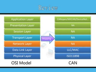
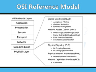
OSI Model CAN
ApplicationLayer
Presentation Layer
Session Layer
Transport Layer
Network Layer
Data Link Layer
Physical Layer
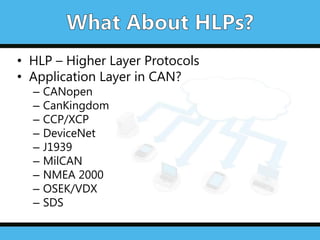
CANopen/MilCAN/DeviceNet…
NA
NA
NA
NA
LLC/MAC
ISO11898
Mapping
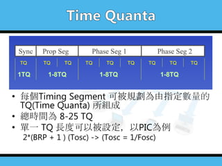
4.
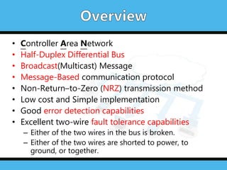
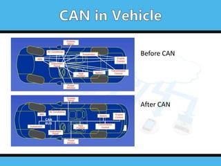
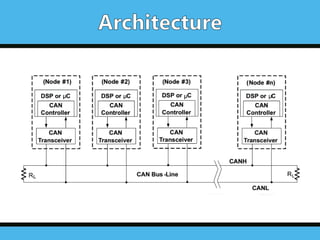
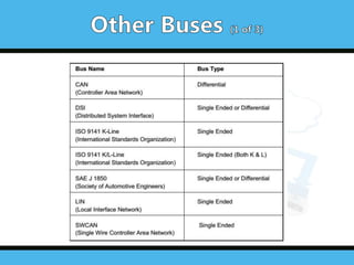
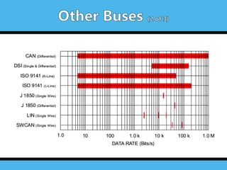
• Controller AreaNetwork
• Half-Duplex Differential Bus
• Broadcast(Multicast) Message
• Message-Based communication protocol
• Non-Return–to-Zero (NRZ) transmission method
• Low cost and Simple implementation
• Good error detection capabilities
• Excellent two-wire fault tolerance capabilities
– Either of the two wires in the bus is broken.
– Either of the two wires are shorted to power, to
ground, or together.
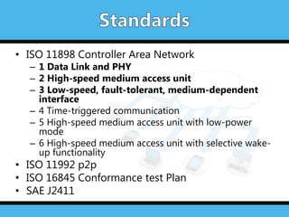
• ISO 11898Controller Area Network
– 1 Data Link and PHY
– 2 High-speed medium access unit
– 3 Low-speed, fault-tolerant, medium-dependent
interface
– 4 Time-triggered communication
– 5 High-speed medium access unit with low-power
mode
– 6 High-speed medium access unit with selective wake-
up functionality
• ISO 11992 p2p
• ISO 16845 Conformance test Plan
• SAE J2411
9.
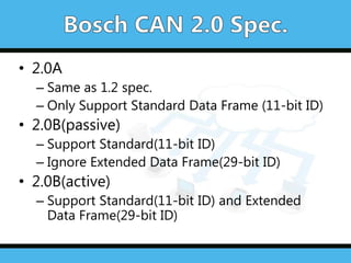
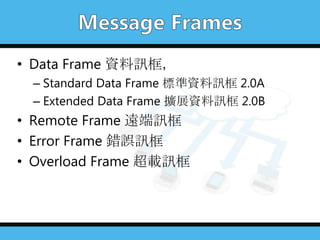
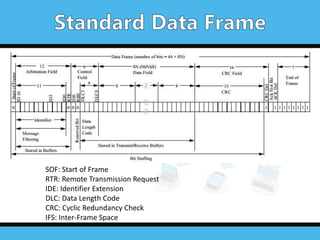
• 2.0A
– Sameas 1.2 spec.
– Only Support Standard Data Frame (11-bit ID)
• 2.0B(passive)
– Support Standard(11-bit ID)
– Ignore Extended Data Frame(29-bit ID)
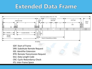
• 2.0B(active)
– Support Standard(11-bit ID) and Extended
Data Frame(29-bit ID)
10.
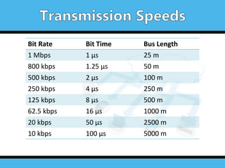
Bit Rate BitTime Bus Length
1 Mbps 1 µs 25 m
800 kbps 1.25 µs 50 m
500 kbps 2 µs 100 m
250 kbps 4 µs 250 m
125 kbps 8 µs 500 m
62.5 kbps 16 µs 1000 m
20 kbps 50 µs 2500 m
10 kbps 100 µs 5000 m
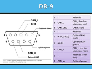
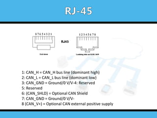
1: CAN_H =CAN_H bus line (dominant high)
2: CAN_L = CAN_L bus line (dominant low)
3: CAN_GND = Ground/0 V/V-4: Reserved
5: Reserved
6: (CAN_SHLD) = Optional CAN Shield
7: CAN_GND = Ground/0 V/V-
8 (CAN_V+) = Optional CAN external positive supply
27.
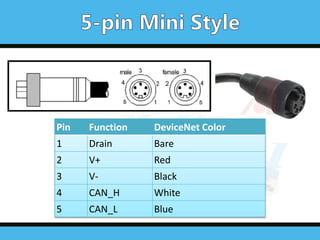
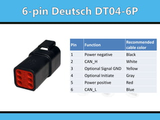
Pin Function
Recommended
cable color
1Power negative Black
2 CAN_H White
3 Optional Signal GND Yellow
4 Optional Initiate Gray
5 Power positive Red
6 CAN_L Blue
28.
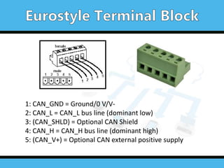
1: CAN_GND =Ground/0 V/V-
2: CAN_L = CAN_L bus line (dominant low)
3: (CAN_SHLD) = Optional CAN Shield
4: CAN_H = CAN_H bus line (dominant high)
5: (CAN_V+) = Optional CAN external positive supply
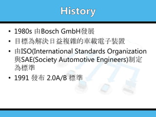
• BOSCH, “CANSpecification version 2.0”, 1991
• Marco Di Natale, “Understanding and using the Controller Area
Network”, October 30, 2008
• Microchip, “AN713 – Controller Area Network(CAN) Basics”, Sep. 2005
• Microchip, "CAN Workshop 202”
• Freescale, “Analog Bus Communication and Products”
• Wikipedia – CAN bus


![[智慧創新應用自造松]LPWAN]技術現況與應用實務](https://cdn.slidesharecdn.com/ss_thumbnails/20170701-lpwanv1-170701080729-thumbnail.jpg?width=640&height=640&fit=bounds)


