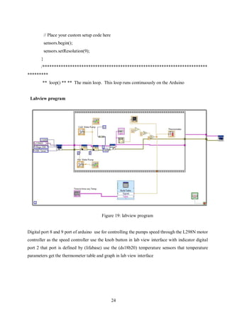
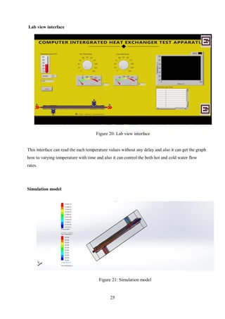
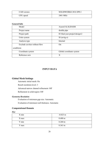
This document presents the final report for the development of a computer integrated heat exchanger test apparatus for a university's thermodynamics laboratory. The report describes the design and fabrication of the apparatus, which allows users to test different types of heat exchangers and vary parameters like temperature, flow rate, and exchanger type. It also outlines the controls and software used, including Arduino and LabVIEW, and presents preliminary testing results. The apparatus aims to provide a low-cost option for analyzing heat exchanger performance compared to commercial units.


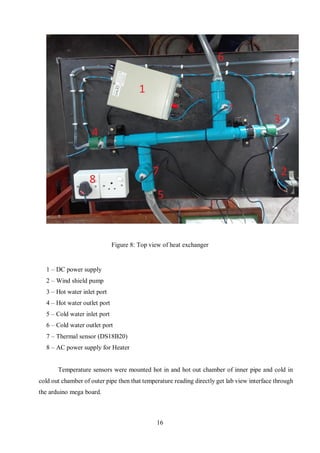
![4
LITERATURE REVIEW
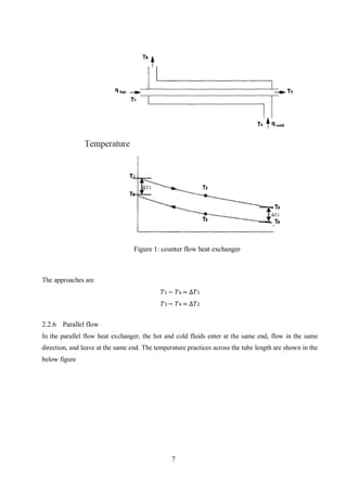
Heat exchanger is a device, such as an automobile radiator, used to transfer heat from a fluid on one
side of a barrier to a fluid on the other side without bringing the fluid into direct contact. Usually,
this barrier is made from metal which has good thermal conductivity in order to transfer heat
effectively from one fluid to another fluid. Besides that, heat exchanger can be defined as any of
several devices that transfer heat from a hot to a cold fluid. In engineering practical, generally, the
hot fluid is needed to cool by the cold fluid. For example, the hot vapor is needed to be cool by
water in condenser practical. Moreover, heat exchanger is defined as a device used to exchange heat
from one medium to another often through metal walls, usually to extract heat from a medium
flowing between two surfaces. In automotive practice, radiator is used as heat exchanger to cool
hot water from engine by air surrounding same like intercooler which used as heat exchanger to
cool hot air for engine intake manifold by Air surrounding. Usually, this device is made from
aluminum since it is lightweight and good thermal conductivity.
2.1 Function of heat exchanger
Heat exchanger is a special equipment type because when heat exchanger is directly fired by a
combustion process, it becomes furnace, boiler, heater, tube-still heater and engine. Vice versa,
when heat exchanger makes a change in phase in one of flowing fluid such as condensation of steam
to water, it becomes a chiller, evaporator, sublimate, distillation-column reboiler, still, condenser
or cooler-condenser. Heat exchanger may be designed for chemical reactions or energy-generation
processes which become an integral part of reaction system such as a nuclear reactor, catalytic
reactor or polymer. Normally, heat exchanger is used only for the transfer and useful elimination or
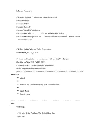
recovery of heat without changed in phase. The fluids on either side of the barrier usually liquids
but they can be gasses such as steam, air and hydrocarbon vapor or can be liquid metals such as
sodium or mercury. In some application, heat exchanger fluids may use fused salts [2].](https://image.slidesharecdn.com/0a9daa0f-0668-43a8-8d6b-c28c9dd5a723-170105180109/85/COMPUTER-INTERGRATED-HEAT-EXCHANGER-LABORATORY-APPARATUS-10-320.jpg)
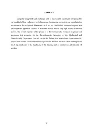
![31
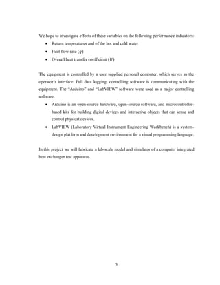
Partial cells 8504
Irregular cells 0
Trimmed cells 0
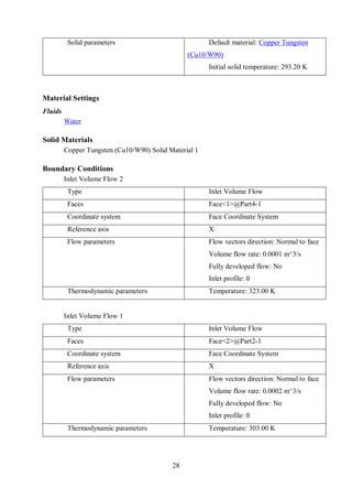
Min/Max Table
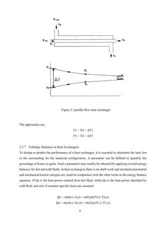
Name Minimum Maximum
Density (Fluid)
[kg/m^3]
987.52 987.52
Density (Solid)
[kg/m^3]
17170.00 17170.00
Pressure [Pa] 101318.14 101981.74
Temperature [K] 304.00 323.00
Temperature (Fluid)
[K]
304.00 323.00
Temperature (Solid)
[K]
323.00 323.00
Velocity [m/s] 0 2.311
Velocity (X) [m/s] -2.311 8.985e-024
Velocity (Y) [m/s] -0.005 0.005
Velocity (Z) [m/s] -0.008 0.009
Velocity RRF [m/s] 0 2.311
Velocity RRF (X)
[m/s]
-2.311 8.985e-024
Velocity RRF (Y)
[m/s]
-0.005 0.005
Velocity RRF (Z)
[m/s]
-0.008 0.009
Vorticity [1/s] 1.62e-023 1503.49
Relative Pressure [Pa] -6.86 656.74
Shear Stress [Pa] 2.90e-026 16.65
Bottleneck Number [ ] 2.0700438e-017 1.0000000
Heat Flux [W/m^2] 1.576e-004 0.911](https://image.slidesharecdn.com/0a9daa0f-0668-43a8-8d6b-c28c9dd5a723-170105180109/85/COMPUTER-INTERGRATED-HEAT-EXCHANGER-LABORATORY-APPARATUS-37-320.jpg)
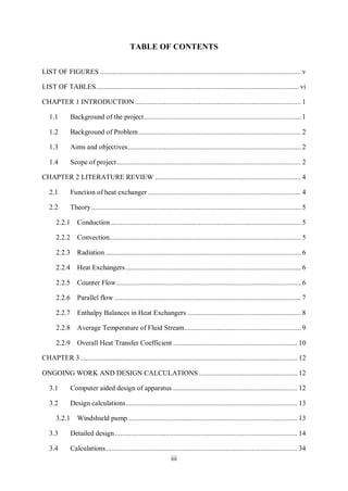
![32
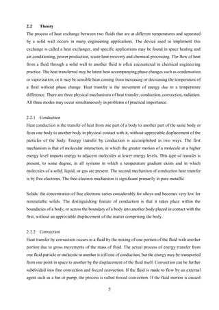
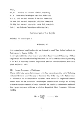
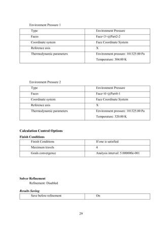
Heat Transfer
Coefficient [W/m^2/K]
1.866e-009 0.028
Overheat above
Melting Temperature [K]
-1030.150 -1030.150
ShortCut Number [ ] 7.9225902e-031 1.0000000
Surface Heat Flux
[W/m^2]
-0.828 0.358
Engineering Database
Solids
Copper Tungsten (Cu10/W90)
Path: Solids Pre-DefinedAlloys
Density: 17170.00 kg/m^3
Specific heat: 149.2 J/(kg*K)
Conductivity type: Isotropic
Thermal conductivity: 160.0000 W/(m*K)
Electrical conductivity: Conductor
Resistivity: 6.4000e-008 Ohm*m
Radiation properties: No
Melting temperature: Yes
Temperature: 1353.15 K
Liquids
Water
Path: Liquids Pre-Defined](https://image.slidesharecdn.com/0a9daa0f-0668-43a8-8d6b-c28c9dd5a723-170105180109/85/COMPUTER-INTERGRATED-HEAT-EXCHANGER-LABORATORY-APPARATUS-38-320.jpg)
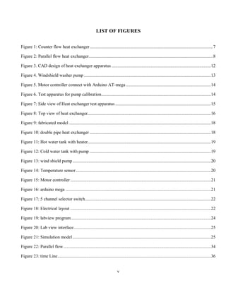
![33
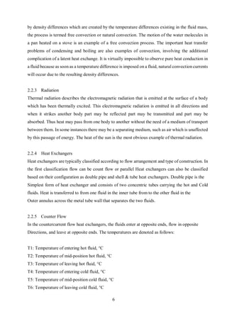
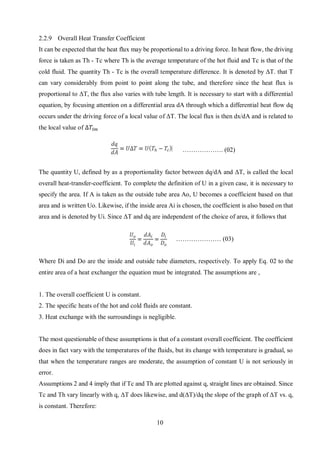
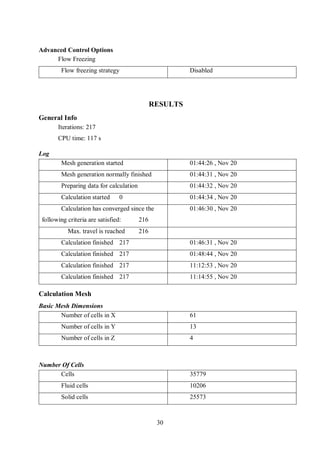
Density
Dynamic viscosity
Specific heat (Cp)
Thermal conductivity
0
200
400
600
800
1000
1200
0 100 200 300 400 500 600
Density[kg/m^3]
Temperature[K]
0
0.0005
0.001
0.0015
0.002
0 100 200 300 400 500 600
Dynamicviscosity[Pa*s]
Temperature[K]
0
0.1
0.2
0.3
0.4
0.5
0.6
0.7
0.8
0 100 200 300 400 500 600
Thermalconductivity[W/(m*K)]
Temperature[K]
4100
4200
4300
4400
4500
4600
4700
4800
4900
0 100 200 300 400 500 600
Specificheat(Cp)[J/(kg*K)]
Temperature[K]](https://image.slidesharecdn.com/0a9daa0f-0668-43a8-8d6b-c28c9dd5a723-170105180109/85/COMPUTER-INTERGRATED-HEAT-EXCHANGER-LABORATORY-APPARATUS-39-320.jpg)
![37
BIBLIOGRAPHY
[1] A. Ltd, “Computer Controlled Heat Exchanger Service Module,” Armfield Ltd, 2016.
[Online]. Available: http://discoverarmfield.com/en/products/view/ht30xc/computer-
controlled-heat-exchanger-service-module. (May 2016)
[2] M. S. BIN ALIAS, “DESIGN OF SMALL HEAT EXCHANGER,” 2010.
[3] D. P. F. P. I. A. S. L. DeWitt, willey, 7th ed. wiley, 2011.](https://image.slidesharecdn.com/0a9daa0f-0668-43a8-8d6b-c28c9dd5a723-170105180109/85/COMPUTER-INTERGRATED-HEAT-EXCHANGER-LABORATORY-APPARATUS-43-320.jpg)
![38
APPENDIX
DEPARTMENT OF MECHANICAL AND MANUFACTURING ENGINEERING
M3 – THERMODYNAMIC LABORATORY
MEXXXX: HEAT TRANSFER
Lab sheet
DATE :
TITLE : OVERALL HEAT TRANSFER COEFFICIENT
AIM :
NOTATIONS:
Symbol
To evaluate the performance of a Heat Exchanger in
counter flow under variations of flow rates
Description Units
U Overall heat transfer coefficient [kW/𝑚2
K]
A Hot water tube surface area [𝑚2
]
𝑚̇ ℎ Mass flow rate of hot water [kg/s]
𝐶ℎ Specific heat of hot water [J/kg K]
𝑇1 Cold water inlet Temperature [K]
𝑇2 Cold water outlet Temperature [K]
𝑇3 Hot water inlet Temperature [K]
𝑇4 Hot water outlet Temperature [K]
𝑇5 Hot water reservoir tank Temp. [K]
∆𝑇1 , ∆𝑇2 Temperature difference [K]
𝑄ℎ Heat emitted by cold water [K]
∆𝑇𝑙𝑚 LMTD value [K]
THEORY:
Applying the First Law of Thermodynamics, to the hot water side,
𝑄ℎ = 𝑚̇ ℎ (𝑇3 − 𝑇4)](https://image.slidesharecdn.com/0a9daa0f-0668-43a8-8d6b-c28c9dd5a723-170105180109/85/COMPUTER-INTERGRATED-HEAT-EXCHANGER-LABORATORY-APPARATUS-44-320.jpg)
![40
DATA:
Diameter of copper tube = 0.01m
Length of copper tube = 0.50m
CALCULATIONS:
Find the overall heat transfer coefficient for Copper and Water.
RESULTS:
Write the results you obtained.
DISCUSSION:
Write a discussion describing the following points.
1. Practical importance of the experiment.
2. State the assumptions you made during the practical.
3. Point out the problems associated with the practical.
4. Mention the reasons for the deviation of the values you obtained from the theoretical values.
REFERENCE:
[1] “Experiment Lab Manual.” [Online]. Available:
https://web.njit.edu/~me/ME_406_Exp6_Lab_Manual.pdf. [Accessed: 19-Nov-2016].](https://image.slidesharecdn.com/0a9daa0f-0668-43a8-8d6b-c28c9dd5a723-170105180109/85/COMPUTER-INTERGRATED-HEAT-EXCHANGER-LABORATORY-APPARATUS-46-320.jpg)