This document introduces concepts of stiffness and strength in fiber-reinforced composite materials. It discusses:
1) Composites consist of a matrix reinforced with fibers, such as glass or carbon fibers in a polymer matrix. The fibers have much higher strength and stiffness than traditional materials.
2) The stiffness of a unidirectional composite in the fiber direction can be estimated using a rule of mixtures, based on the fiber and matrix properties and volume fractions. Transverse stiffness is estimated using a series model.
3) Fiber volume fraction, fiber and matrix properties, and fiber orientation determine the composite's anisotropic mechanical properties. Empirical models are used for more complex fiber arrangements.
4) Strength
IRJET- Computation of Failure Index Strength of FML and FRB CompositesIRJET Journal
This document discusses the computation of failure indices of fiber metal laminate (FML) and fiber reinforced polymer (FRP) composites with different fiber orientations. It first provides background on FRP, FML, and different types of laminate configurations. It then outlines the methodology used, which involves using classical lamination theory (CLT) and the ANSYS software to predict stresses in FML and FRP laminates under in-plane tensile loading. Specific laminate stacking sequences of [Al/45/-45/Al] and [00/45/-45/00] are analyzed. Stresses are calculated in the layers and failure indices are determined using Tsai-Wu criterion for the FRP layers and
This document analyzes flutter in a flat composite plate. It begins by defining flutter as a dangerous phenomenon that can occur in flexible structures subjected to aerodynamic forces, including aircraft. Flutter results from interactions between aerodynamic, stiffness, and inertial forces. The document then summarizes the methodology used to model and analyze flutter in a composite plate wing structure with different ply orientations. It describes the basic flutter motion of aircraft wings and introduces the concept of aeroelastic tailoring to control deformation. The mechanics of composites and property averaging methods used to determine composite properties are also overviewed.
Application of CAD and SLA Method in Dental ProsthesisIDES Editor
Placement of dental implants requires precise
planning that accounts for anatomic limitations and
restorative goals. Diagnosis can be made with the assistance
of computerized tomographic scanning, but transfer of
planning to the surgical field is limited. Precise implant
placement no longer relies upon so called mental-navigation
but rather can be computer guided, based on a three
dimensional prosthetically directed plan. Recently, novel CAD/
CAM techniques such as stereolithographic rapid prototyping
have been developed to build surgical guides in an attempt to
improve precision of implant placement. The purpose of this
paper is to discuss the use of scanning equipments to transfer
clinically relevant prosthetic information which can be used
for fabrication of stereolithographic medical models and
surgical guides. The proposed method provides solid evidence
that computer-aided design and manufacturing technologies
may become a new avenue for custom-made dental implants
design, analysis, and production in the 21st century.
This document summarizes research on developing a multi-scale modeling approach to predict the structural behavior of carbon fiber reinforced composite pipes used for offshore oil and gas risers. The approach models the pipe behavior at the micro, meso, and macro scales and links the scales together. Experiments were conducted to validate the modeling approach and determine material properties at each scale. Results showed good agreement between predicted and experimental properties and structural response at different loading conditions. The multi-scale modeling approach shows promise for designing composite risers while addressing current limitations in experience, standards, and design methodologies.
1) The document outlines the key concepts and formulas related to tensile testing of materials including stress, strain, Young's modulus, yield point, and tensile strength.
2) A tensile test involves applying a controlled tensile force to a material sample to determine properties like elasticity, plasticity, and ultimate tensile strength.
3) Important points on the stress-strain graph are identified including the yield point, elastic limit, and fracture point.
The document discusses modelling polymers under tension. It introduces various polymer models including freely jointed chain, freely rotating chain, Gaussian chain and worm like chain models. It then describes the Lagowski Noolandi model in more detail. The document also discusses force-extension curves and how they can provide insight into polymer unfolding under tension. Finally, it presents results comparing force-extension curves for homopolymers and random block copolymers under varying parameters such as stiffness and composition.
1. The document presents an overview of fracture mechanics, including an atomic view of fracture, stress concentration effects of flaws, the Griffith energy balance approach, and the energy release rate.
2. It discusses how cracks propagate when sufficient stress is applied at the atomic level to break atomic bonds, and how flaws concentrate stress which can cause fracture at lower overall stresses than theoretical strength estimates.
3. The Griffith energy balance approach is summarized, showing how the energy required to create new crack surfaces must be balanced by the strain energy released from the material as the crack extends.
FRACTURE MECHANICS OF NANO-SILICA PARTICLES IN REINFORCED EPOXIES Jordan Suls
This document summarizes a study that used finite element modeling to examine how different levels of particle dispersion (evenly dispersed, moderately clumped, and severely clumped) affect the fracture mechanics of nanosilica particle reinforced epoxies. Three models were created in Abaqus with the different dispersion levels and subjected to tensile loading. The results found that the evenly dispersed model had the highest fracture toughness, as indicated by its ability to withstand a greater force at similar displacements. This was because the clumped models developed large stress regions around the clumps that caused earlier debonding of the particle-matrix interfaces and faster crack propagation.
ESA Module 4 Part-A ME832. by Dr. Mohammed ImranMohammed Imran
1. The stress-freezing method is used to analyze stresses in 3D photoelastic models. In this method, a model made of a polymeric material is loaded, which causes deformation of its primary and secondary molecular bonds.
2. The model is then heated so that the secondary bonds break but the primary bonds remain intact while still under load. Upon cooling, the secondary bonds reform and lock the deformations caused by the load into the primary bonds.
3. After removing the load, the deformations remain locked in the model. Thin slices can then be cut from the model to photoelastically analyze stresses in its interior using the birefringent properties of the locked deformations.
The document compares different methods for analyzing the structural behavior of segmental tunnel linings, including beam and spring models (BSM) and 3D finite element method (FEM) calculations. BSM analyses with coupled, hinged rings provide sufficient results for regular structural design cases but 3D-FEM is needed when special cases require considering the spatial bearing behavior of joints. Calculations using the different methods for a sample configuration show similar bending moments and deformations, indicating BSM is adequate for usual tunnel lining designs where loads do not vary longitudinally.
The Topic Is about Textile Fiber Strength (Stress) & StrainApu Arafat
This presentation discusses fiber strength and strain. It defines stress as the resistance per unit area to deformation when an external force acts on a body. Strain is defined as the deformation per unit length. A stress-strain curve is presented for textile fibers, showing the relationship between stress and strain. Hooke's law is described, which states that within the elastic limit, the ratio of stress to strain is constant. This constant is known as the modulus of elasticity or Young's modulus. The presentation concludes with a discussion of the strength versus toughness dilemma by examining the stress-strain curve.
Torsional evaluation of Tapered Composite Cone using Finite Element AnalysisIOSR Journals
Composite material is one of the most important and economical material for the various application
due to its favorable properties .Recently many researches are going on the various properties of the these
materials .In this paper an anisotropic behavior of the composite tube is to be modeled and analysis is to be
performed under torsional loading conditions. Torsion is a tricky phenomenon in composite cylinders as the
twist effects and their interactions with composite shells induce complex stress patterns. The objective behind
the study is to understand interaction of conical angle, length of tube and torsional moment .it also includes
comparative analysis of deformation and stresses developed in tapered composite cone due to use of various
materials like steel, orthotropic composite and laminated composite etc. The effect of taper angle, thickness of
the tube and fiber orientations in case of laminated composite is studied by using finite element analysis (ANSYS
software). The finite element analysis is especially versatile and efficient for the analysis of complex structural
behavior of the composite laminated structures. It is found that deformation in case of laminated composite and
deformation in between steel and laminated composite cone. At membrane stresses are observed at the middle of
cone in length direction for three materials.
A new method is developed for determining material hardness from depth sensing indentation tests. Both loading and unloading data are used to calculate Meyer hardness values, which agree well with conventional optical measurements. While the new method characterizes hardness even for elastic materials, the conventional mean contact pressure definition differs significantly from hardness for elastic materials. A relationship is found between work during loading and unloading that allows hardness to be calculated using only load-depth data.
This document discusses strength parameters for clays, including:
- The peak friction angle for clays decreases with increasing plasticity index and activity. Critical state friction angles range from 20-25° for kaolin clays and 20° for montmorillonite clays.
- The Hvorslev failure envelope models the strength of overconsolidated clays using equivalent friction angle and cohesion parameters.
- Undrained shear strength of clays decreases with increasing liquidity index and increases with overconsolidation ratio. Empirical equations relate strength to plasticity index and preconsolidation stress.
- Shear bands form after peak strength due to strain localization. Their thickness is 7-10 particle diameters
This document discusses the key characteristics of soil strength and deformation behavior. It introduces the Mohr-Coulomb failure criterion and explains that soil strength depends on factors like effective stress, void ratio, composition, and stress history. It describes the different failure envelopes for peak, critical, and residual strength. It also discusses concepts like dilatancy, anisotropy, and how strength is influenced by factors like density, drainage conditions, overconsolidation ratio, and temperature. The document emphasizes the fundamental factors controlling soil strength and stress-deformation behavior.
This document summarizes a study on developing a fracture mechanics model to predict the insertion force of needles cutting through tissue. Experimental tests were conducted to determine the fracture toughness, shear modulus, frictional force, and crack length for different size needles inserted at various speeds into porcine skin. A force model was developed incorporating these parameters and validated against experimental force measurements, with errors less than 0.2 N. The model accurately predicts insertion forces and shows that 61% of the force comes from creating a crack in the tissue, while 21% is from friction and 18% from spreading the tissue. Increasing insertion speed was found to not reduce force for porcine skin.
RESULTS OF FINITE ELEMENT ANALYSIS FOR INTERLAMINAR FRACTURE REINFORCED THERM...MSEJjournal1
The double cantilever beam (DCB) is widely used for fracture toughness testing and it has become popular
for opening-mode (mode I) delamination testing of laminated composites. Delamination is a crack that
forms between the adjacent plies of a composite laminate at the brittle polymer resin. This study was
conducted to emphasize the need for a better understanding of the DCB specimen of different fabric
reinforced systems (carbon fibers) with a thermoplastic matrix (EP, PEI), by using the extended finite
element method (X-FEM). It is well known that in fabric reinforced composites fracture mechanisms
include microcracking in front of the crack tip, fiber bridging and multiple cracking, and both contribute
considerably to the high interlaminar fracture toughness measured. That means, the interlaminar fracture
toughness of a composite is not controlled by a single material parameter, but is a result of a complex
interaction of resin, fiber and interface properties.
Abstract. Ensuring of permanent and continuous working process of oil-gas and field equipment alongside with the other factors, depends also on reliability of sealing units. A problem of deterioration modeling of a sealing element of a packer including into an oil field equipment complex is considered in this paper.
The document proposes an additive margin softmax loss function to improve on the standard softmax loss for deep face recognition. It aims to minimize intra-class variation by adding a regularization term to penalize feature-to-center distances and using a scale parameter, which produces higher gradients to further shrink variance within classes. This approach incorporates a fixed hard angular margin, unlike angular softmax which only imposes an unfixed margin, helping to push classification boundaries closer to each class's weight vector.
Flexural Properties of Fiber | Flexural Properties of Textile FiberMd Rakibul Hassan
Flexural properties refer to how textile materials like fibers, yarns, and fabrics behave under bending. Flexural rigidity is the resistance of a textile fiber to bending and is measured as the couple required to bend the fiber to a unit curvature. Specific flexural rigidity expresses this value per unit linear density. Bending recovery is the ability of a fiber to recover from bending, while bending modulus is the ratio of bending stress to bending strain. Flexural properties influence behaviors like yarn structure, fabric drape and handle, recovery, wear performance, and fiber arrangement in yarns.
This document summarizes an article that studied orientation gradients and geometrically necessary dislocations (GNDs) in two ultrafine grained dual-phase steels with different martensite particle size and volume fraction. High-resolution electron backscatter diffraction (EBSD) was used to quantify orientation gradients, pattern quality, and GND density variations at ferrite-ferrite and ferrite-martensite interfaces. Two methods were demonstrated to calculate GND density from the EBSD data based on kernel average misorientation and dislocation density tensor. The overall GND density was shown to increase with increasing total martensite fraction, decreasing grain volume, and increasing martensite fraction in the vicinity of ferrite.
Electronic Structure and optical properties of Co2TiZ Heusler alloysDr. Vishal Jain
The document summarizes research on the electronic structure, magnetic, and optical properties of Co2TiZ (Z = B, Al, Ga, In) Heusler alloys using density functional theory. Key findings include:
- Co2TiAl exhibits true half metallic ferromagnetism with 100% spin polarization and a spin-flip gap of 0.25 eV, making it suitable for spintronics.
- Co2TiZ (Z = B, Al, Ga) show stable half metallicity over a wide range of pressures, again making them suitable for thin film applications.
- Lattice constants decrease with increasing pressure for all alloys, with spin polarization also decreasing for Co2
The document contains questions from multiple individuals about metallurgy concepts such as Burger vectors, Schottky defects, slip systems, and point defects. Members provide concise answers explaining these concepts, including mathematical equations where applicable. One group question is also included covering topics like strengthening mechanisms, recovery/recrystallization/grain growth, defects, dislocations, and twinning.
This document discusses simulating fatigue damage in solder joints using cohesive zone modeling. It introduces cohesive zone modeling as a numerical method to describe interface mechanics and model crack initiation and propagation. The document proposes using a cohesive zone model with a damage variable to simulate fatigue damage accumulation over successive loading cycles at solder interfaces. The model represents interfaces with cohesive elements having traction-separation laws that degrade nonlinearly based on a damage evolution law to capture fatigue failure below static strength limits.
The document summarizes research on the magnetic properties of Tbx(FeCoV)1002x films deposited under different sputtering conditions. Key findings include:
1) A minimum out-of-plane saturation magnetization and maximum out-of-plane coercivity were obtained for films near x=23, while the second highest saturation magnetization and relatively low coercivity were at x=40.
2) For Tb40(FeCoV)60 films, out-of-plane saturation magnetization first increased to a maximum then decreased with increasing sputtering pressure/power, while coercivity monotonically decreased with increasing power.
3) Optimum sputtering pressure and power were found to produce the strongest perpendicular
This document introduces concepts of stiffness and strength in fiber-reinforced composite materials. It discusses how the microscopic properties of the constituents - fibers and matrix - relate to the macroscopic engineering properties of the composite. Specifically:
- Composites are made of a fiber reinforcement within a matrix. The fibers carry most of the load while the matrix holds them together and protects them.
- The stiffness and strength of a unidirectional composite can be estimated using simple "rule of mixtures" formulas that are functions of the fiber and matrix properties and their volume fractions.
- The fiber properties have a dominant effect on the longitudinal stiffness and strength, while the transverse properties are more dependent on the matrix properties.
-
1) The document discusses the behavior and properties of unidirectional composites, which consist of parallel fibers embedded in a matrix. It describes methods for predicting the longitudinal and transverse stiffness and strength of these composites.
2) The rule of mixtures is presented as a way to calculate the longitudinal stiffness and strength of a composite based on the properties of its constituents and their volume fractions. Factors that influence the longitudinal properties are also discussed.
3) Transverse properties are generally much lower than longitudinal properties due to the orientation of the fibers. Methods for predicting transverse stiffness using elasticity principles are described. Failure modes in composites include fiber breaking and matrix microcracking.
Effective properties of composite materialsKartik_95
1. The document discusses effective material properties of fiber reinforced composites using micromechanics. It relates volume averaged stresses and strains in a representative volume element (RVE) to determine effective composite properties.
2. It presents equations for volume fractions and density of constituents using a "rule of mixtures" approach. Maximum theoretical fiber volume fractions are calculated for ideal square and triangular fiber arrays.
3. Elementary mechanics of materials models are used to predict longitudinal modulus, transverse modulus, Poisson's ratio and shear modulus of a fiber reinforced lamina. The models assume perfect bonding and uniform stresses/strains between fibers and matrix.
This document discusses modeling the elastic properties of laminated composites. It first defines composites as materials made of two or more distinct constituent materials. It then discusses various properties of composites like strength and corrosion resistance. It classifies composites based on their matrix material and reinforcement type. It also discusses volume and weight fractions. Rules of mixture are presented for calculating longitudinal and transverse modulus. Stress-strain relationships and analysis methods for orthotropic laminates are described. Forces, moments, and the inverse of the stiffness matrix for laminated composites are defined. Computer simulation of composite modeling allows for virtual testing of multiple design scenarios.
Three composite models in stress , strain and elastic modulusMohammed Layth
The document discusses three models for composite materials:
1) The parallel phase model where the dispersed phase is embedded in a continuous matrix phase. It determines the elastic modulus (E1) of the composite in the fiber direction based on the modulus and volume fraction of the fibers and matrix.
2) The series phase model where the rule of mixtures relates the composite modulus to the modulus and volume fraction of the matrix and dispersed materials.
3) The dispersed phase model, also called the Maxwell model, which is not described in detail.
My name is Paulin O. I am associated with solidworksassignmenthelp.com for the past 10 years and have been helping the engineering students with their assignments I have a Masters in mechanical Engineering from Cornell University, USA.
Experiment NO:6 describes a compression test performed on an anisotropic wooden material to determine its compressive strength when force is applied both parallel and perpendicular to its fibers. When force was applied perpendicular to the fibers, the wooden block failed at a compressive strength of 4.7712x10⁷ N/m2. When applied parallel to the fibers, the failure strength was lower at 1.204x10⁷ N/m2. Detailed load-deformation data is provided in tables showing that the material can withstand over 10 times more load when compressed parallel rather than perpendicular to its fibers, as the fibers act like columns parallel to the load.
The document discusses reaction rate theory applied to atomic-scale wear. It summarizes previous studies that revealed atom-by-atom wear can occur and describes how the Eyring equation, originally developed to describe chemical reaction rates, has been applied as a mean field model for atomistic wear. The Eyring equation assumes reactants have a Boltzmann distribution of energies, but its direct application to atomic wear is limited since the stress landscape and activation barriers for wear are complex and not fully understood. Preliminary data on the velocity dependence of wear is presented, but more work is needed to validate existing wear models and understand dependencies on factors like temperature and stress.
This document contains solutions to three problems involving stress and strain transformations for composite materials with different fiber orientations. Problem 5.2 involves computing the safety factor for a composite layer under loading using material data from a table. Problem 5.3 calculates the rotation matrix and transformed stiffness matrix for a layer oriented at a certain angle. Problem 5.5 parts (a) and (b) find the strains in both material and global coordinate systems for a tensile test specimen with fibers at an angle, and part (c) determines if the cross section experiences uniaxial strain and explains the origin of any non-zero strains.
The document discusses different possible shapes of Möbius bands based on a discrete lattice model that accounts for both in-plane stretching and out-of-plane bending. The model predicts four characteristic shapes depending on the dimensionless parameter k ̃, which represents the ratio of in-plane stretchability to out-of-plane bendability. Very low stretchability leads to developable bands, while higher stretchability results in more complex twisted shapes with expanded circular centerlines or self-intersecting forms. The shapes transition continuously from developable to highly stretchable as k ̃ increases.
This document discusses a finite element analysis of plastic behavior in metal matrix composite laminates. It aims to study stress fields around fibers at free edges of laminates under thermal and mechanical loads, and how damage from plastic deformation affects stresses. The analysis uses micromechanical models of cross-ply laminates with fibers in different orientations. Results on stress distributions with and without considering plasticity and damage are presented and compared to previous research. The goal is to better understand delamination in composites and how fiber/matrix debonding at free edges relates to the overlapping hypothesis of thermal stress generation at fiber ends.
This document discusses mathematical models used to calculate transmembrane potential in cell walls exposed to electric fields. It begins by introducing the topic and its importance in bioelectrical physics simulations. The document then presents three generations of models with increasing complexity:
1) The first generation model assumes a spherical cell geometry and derives Schwann's equation to calculate transmembrane potential as a function of the applied electric field and position on the cell surface.
2) The second generation model improves on this by using an ellipsoidal cell geometry, leading to a more complex solution involving elliptic integrals.
3) The third generation aims to model pulsed electric fields by considering the cell's potential to decay exponentially after a pulse, like a capacitor
Stress-Strain Curves for Metals, Ceramics and PolymersLuís Rita
Homework II - Biomaterials Science
We are interested about studying and comparing stress-strain curves of metals, ceramics and polymers. Primarily, differences are due to their different chemical bonding properties.
IST - 4th Year - 2nd Semester - Biomedical Engineering.
The document discusses finite element methods (FEM) for modeling static and dynamic responses to applied forces. It describes how FEM involves discretizing a global continuum model into a nodal mesh and representing the governing equations as a stiffness matrix. Both linear elastic and nonlinear inelastic deformations can be modeled using FEM by approximating the elastic potential energy.
Modeling and Analysis of Laminated Composite Beams using Higher Order TheoryIDES Editor
The present study deals with the assessment of
higher order theory of laminated beams under static
mechanical loads. The theory has been presented for general
lay-up of the laminate. The displacement field is expressed in
terms of only three primary displacement variables by
satisfying exactly the conditions of zero transverse shear stress
at the top and bottom and its continuity at layer interfaces.
The governing equations of motion and boundary conditions
are derived using virtual work. The number of primary
displacement unknowns is three, which is independent of the
number of layers and equal in number to the ones used in the
first order shear deformation theory. Higher order theory thus
preserves the computational advantage of an equivalent single
layer theory. The Third order theory and First order shear
deformation theory are assessed by comparison with the exact
two-dimensional elasticity solution of the simply-supported
beam. A theory is good only if it yields accurate results for all
kinds of loads and for any lay-up of the beam. For this purpose,
parametric studies for composite laminates and sandwich
beams are conducted.
1. The strength of materials is dictated not by bond strength alone, but also by defects. According to Griffith's equation, as defects get smaller or are eliminated, strength increases.
2. Defects have no effect on a material's modulus, only on its strength. Materials with zero defects would be infinitely strong, which is impossible.
3. The strength of fibers is statistical and depends on the probability of critical defects occurring based on the fiber's size and applied stress, following a Weibull distribution. Larger fibers have a higher probability of failure.
A fully integrated discrete fracture model (DFM) is presented for coupled geomechanics and single-phase fluid flow in fractured porous media. The model discretizes the poroelasticity equations using finite elements on an unstructured grid, with special treatment for fractures. The flow equations are discretized using finite volumes. A sequential implicit solution strategy is employed to solve the coupled nonlinear equations. Changes in porosity and fracture permeability due to mechanical deformation are accounted for. The model aims to explicitly represent fracture geometry and its impact on stress/strain fields, unlike dual-continuum approaches. It is implemented within a general-purpose research simulator.
HR search is critical to a company's success because it ensures the correct people are in place. HR search integrates workforce capabilities with company goals by painstakingly identifying, screening, and employing qualified candidates, supporting innovation, productivity, and growth. Efficient talent acquisition improves teamwork while encouraging collaboration. Also, it reduces turnover, saves money, and ensures consistency. Furthermore, HR search discovers and develops leadership potential, resulting in a strong pipeline of future leaders. Finally, this strategic approach to recruitment enables businesses to respond to market changes, beat competitors, and achieve long-term success.
Presentation by Herman Kienhuis (Curiosity VC) on Investing in AI for ABS Alu...Herman Kienhuis
Presentation by Herman Kienhuis (Curiosity VC) on developments in AI, the venture capital investment landscape and Curiosity VC's approach to investing, at the alumni event of Amsterdam Business School (University of Amsterdam) on June 13, 2024 in Amsterdam.
The APCO Geopolitical Radar - Q3 2024 The Global Operating Environment for Bu...APCO
The Radar reflects input from APCO’s teams located around the world. It distils a host of interconnected events and trends into insights to inform operational and strategic decisions. Issues covered in this edition include:
Ellen Burstyn: From Detroit Dreamer to Hollywood Legend | CIO Women MagazineCIOWomenMagazine
In this article, we will dive into the extraordinary life of Ellen Burstyn, where the curtains rise on a story that's far more attractive than any script.
Digital Marketing with a Focus on Sustainabilitysssourabhsharma
Digital Marketing best practices including influencer marketing, content creators, and omnichannel marketing for Sustainable Brands at the Sustainable Cosmetics Summit 2024 in New York
Profiles of Iconic Fashion Personalities.pdfTTop Threads
The fashion industry is dynamic and ever-changing, continuously sculpted by trailblazing visionaries who challenge norms and redefine beauty. This document delves into the profiles of some of the most iconic fashion personalities whose impact has left a lasting impression on the industry. From timeless designers to modern-day influencers, each individual has uniquely woven their thread into the rich fabric of fashion history, contributing to its ongoing evolution.
Storytelling is an incredibly valuable tool to share data and information. To get the most impact from stories there are a number of key ingredients. These are based on science and human nature. Using these elements in a story you can deliver information impactfully, ensure action and drive change.
𝐔𝐧𝐯𝐞𝐢𝐥 𝐭𝐡𝐞 𝐅𝐮𝐭𝐮𝐫𝐞 𝐨𝐟 𝐄𝐧𝐞𝐫𝐠𝐲 𝐄𝐟𝐟𝐢𝐜𝐢𝐞𝐧𝐜𝐲 𝐰𝐢𝐭𝐡 𝐍𝐄𝐖𝐍𝐓𝐈𝐃𝐄’𝐬 𝐋𝐚𝐭𝐞𝐬𝐭 𝐎𝐟𝐟𝐞𝐫𝐢𝐧𝐠𝐬
Explore the details in our newly released product manual, which showcases NEWNTIDE's advanced heat pump technologies. Delve into our energy-efficient and eco-friendly solutions tailored for diverse global markets.
Cover Story - China's Investment Leader - Dr. Alyce SUmsthrill
In World Expo 2010 Shanghai – the most visited Expo in the World History
https://www.britannica.com/event/Expo-Shanghai-2010
China’s official organizer of the Expo, CCPIT (China Council for the Promotion of International Trade https://en.ccpit.org/) has chosen Dr. Alyce Su as the Cover Person with Cover Story, in the Expo’s official magazine distributed throughout the Expo, showcasing China’s New Generation of Leaders to the World.
The Genesis of BriansClub.cm Famous Dark WEb PlatformSabaaSudozai
BriansClub.cm, a famous platform on the dark web, has become one of the most infamous carding marketplaces, specializing in the sale of stolen credit card data.
How are Lilac French Bulldogs Beauty Charming the World and Capturing Hearts....Lacey Max
“After being the most listed dog breed in the United States for 31
years in a row, the Labrador Retriever has dropped to second place
in the American Kennel Club's annual survey of the country's most
popular canines. The French Bulldog is the new top dog in the
United States as of 2022. The stylish puppy has ascended the
rankings in rapid time despite having health concerns and limited
color choices.”
Part 2 Deep Dive: Navigating the 2024 Slowdownjeffkluth1
Introduction
The global retail industry has weathered numerous storms, with the financial crisis of 2008 serving as a poignant reminder of the sector's resilience and adaptability. However, as we navigate the complex landscape of 2024, retailers face a unique set of challenges that demand innovative strategies and a fundamental shift in mindset. This white paper contrasts the impact of the 2008 recession on the retail sector with the current headwinds retailers are grappling with, while offering a comprehensive roadmap for success in this new paradigm.
Anny Serafina Love - Letter of Recommendation by Kellen Harkins, MS.AnnySerafinaLove
This letter, written by Kellen Harkins, Course Director at Full Sail University, commends Anny Love's exemplary performance in the Video Sharing Platforms class. It highlights her dedication, willingness to challenge herself, and exceptional skills in production, editing, and marketing across various video platforms like YouTube, TikTok, and Instagram.
Anny Serafina Love - Letter of Recommendation by Kellen Harkins, MS.
Composites
1. INTRODUCTION TO COMPOSITE MATERIALS
David Roylance
Department of Materials Science and Engineering
Massachusetts Institute of Technology
Cambridge, MA 02139
March 24, 2000
Introduction
This module introduces basic concepts of stiffness and strength underlying the mechanics of
fiber-reinforced advanced composite materials. This aspect of composite materials technology
is sometimes terms “micromechanics,” because it deals with the relations between macroscopic
engineering properties and the microscopic distribution of the material’s constituents, namely
the volume fraction of fiber. This module will deal primarily with unidirectionally-reinforced
continuous-fiber composites, and with properties measured along and transverse to the fiber
direction.
Materials
The term composite could mean almost anything if taken at face value, since all materials are
composed of dissimilar subunits if examined at close enough detail. But in modern materials
engineering, the term usually refers to a “matrix” material that is reinforced with fibers. For in-
stance, the term “FRP” (for Fiber Reinforced Plastic) usually indicates a thermosetting polyester
matrix containing glass fibers, and this particular composite has the lion’s share of today’s
commercial market. Figure 1 shows a laminate fabricated by “crossplying” unidirectionally-
reinforced layers in a 0◦ -90◦ stacking sequence.
Many composites used today are at the leading edge of materials technology, with perfor-
mance and costs appropriate to ultrademanding applications such as spacecraft. But heteroge-
neous materials combining the best aspects of dissimilar constituents have been used by nature
for millions of years. Ancient society, imitating nature, used this approach as well: the Book of
Exodus speaks of using straw to reinforce mud in brickmaking, without which the bricks would
have almost no strength.
As seen in Table 11 , the fibers used in modern composites have strengths and stiffnesses
far above those of traditional bulk materials. The high strengths of the glass fibers are due to
processing that avoids the internal or surface flaws which normally weaken glass, and the strength
and stiffness of the polymeric aramid fiber is a consequence of the nearly perfect alignment of
the molecular chains with the fiber axis.
1
F.P. Gerstle, “Composites,” Encyclopedia of Polymer Science and Engineering, Wiley, New York, 1991. Here
E is Young’s modulus, σb is breaking stress, b is breaking strain, and ρ is density.
1
2. Figure 1: A crossplied FRP laminate, showing nonuniform fiber packing and microcracking
(from Harris, 1986).
Table 1: Properties of Composite Reinforcing Fibers.
Material E σb b ρ E/ρ σb /ρ cost
(GPa) (GPa) (%) (Mg/m3 ) (MJ/kg) (MJ/kg) ($/kg)
E-glass 72.4 2.4 2.6 2.54 28.5 0.95 1.1
S-glass 85.5 4.5 2.0 2.49 34.3 1.8 22–33
aramid 124 3.6 2.3 1.45 86 2.5 22–33
boron 400 3.5 1.0 2.45 163 1.43 330–440
HS graphite 253 4.5 1.1 1.80 140 2.5 66–110
HM graphite 520 2.4 0.6 1.85 281 1.3 220–660
Of course, these materials are not generally usable as fibers alone, and typically they are
impregnated by a matrix material that acts to transfer loads to the fibers, and also to pro-
tect the fibers from abrasion and environmental attack. The matrix dilutes the properties to
some degree, but even so very high specific (weight-adjusted) properties are available from these
materials. Metal and glass are available as matrix materials, but these are currently very ex-
pensive and largely restricted to R&D laboratories. Polymers are much more commonly used,
with unsaturated styrene-hardened polyesters having the majority of low-to-medium perfor-
mance applications and epoxy or more sophisticated thermosets having the higher end of the
market. Thermoplastic matrix composites are increasingly attractive materials, with processing
difficulties being perhaps their principal limitation.
Stiffness
The fibers may be oriented randomly within the material, but it is also possible to arrange for
them to be oriented preferentially in the direction expected to have the highest stresses. Such
a material is said to be anisotropic (different properties in different directions), and control of
the anisotropy is an important means of optimizing the material for specific applications. At
a microscopic level, the properties of these composites are determined by the orientation and
2
3. distribution of the fibers, as well as by the properties of the fiber and matrix materials. The
topic known as composite micromechanics is concerned with developing estimates of the overall
material properties from these parameters.
Figure 2: Loading parallel to the fibers.
Consider a typical region of material of unit dimensions, containing a volume fraction Vf of
fibers all oriented in a single direction. The matrix volume fraction is then Vm = 1 − Vf . This
region can be idealized as shown in Fig. 2 by gathering all the fibers together, leaving the matrix
to occupy the remaining volume — this is sometimes called the “slab model.” If a stress σ1 is
applied along the fiber direction, the fiber and matrix phases act in parallel to support the load.
In these parallel connections the strains in each phase must be the same, so the strain 1 in the
fiber direction can be written as:
f = m = 1
The forces in each phase must add to balance the total load on the material. Since the forces in
each phase are the phase stresses times the area (here numerically equal to the volume fraction),
we have
σ1 = σf Vf + σm Vm = Ef 1 Vf + Em 1 Vm
The stiffness in the fiber direction is found by dividing by the strain:
σ1
E1 = = Vf Ef + Vm Em (1)
1
This relation is known as a rule of mixtures prediction of the overall modulus in terms of the
moduli of the constituent phases and their volume fractions.
If the stress is applied in the direction transverse to the fibers as depicted in Fig. 3, the slab
model can be applied with the fiber and matrix materials acting in series. In this case the stress
in the fiber and matrix are equal (an idealization), but the deflections add to give the overall
transverse deflection. In this case it can be shown (see Prob. 5)
1 Vf Vm
= + (2)
E2 Ef Em
Figure 4 shows the functional form of the parallel (Eqn. 1) and series (Eqn. 2) predictions for
the fiber- and transverse-direction moduli.
The prediction of transverse modulus given by the series slab model (Eqn. 2) is considered
unreliable, in spite of its occasional agreement with experiment. Among other deficiencies the
3
4. Figure 3: Loading perpendicular to the fibers.
assumption of uniform matrix strain being untenable; both analytical and experimental studies
have shown substantial nonuniformity in the matirx strain. Figure 5 shows the photoelastic
fringes in the matrix caused by the perturbing effect of the stiffer fibers. (A more complete
description of these phtoelasticity can be found in the Module on Experimental Strain Analysis,
but this figure can be interpreted simply by noting that closely-spaced photoelastic fringes are
indicative of large strain gradients.
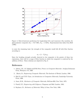
In more complicated composites, for instance those with fibers in more than one direction
or those having particulate or other nonfibrous reinforcements, Eqn. 1 provides an upper bound
to the composite modulus, while Eqn. 2 is a lower bound (see Fig. 4). Most practical cases
will be somewhere between these two values, and the search for reasonable models for these
intermediate cases has occupied considerable attention in the composites research community.
Perhaps the most popular model is an empirical one known as the Halpin-Tsai equation2 , which
can be written in the form:
Em [Ef + ξ(Vf Ef + Vm Em )]
E= (3)
Vf Em + Vm Ef + ξEm
Here ξ is an adjustable parameter that results in series coupling for ξ = 0 and parallel averaging
for very large ξ.
Strength
Rule of mixtures estimates for strength proceed along lines similar to those for stiffness. For
instance, consider a unidirectionally reinforced composite that is strained up to the value at
which the fibers begin to break. Denoting this value f b , the stress transmitted by the composite
is given by multiplying the stiffness (Eqn. 1):
σb = f b E1 = Vf σf b + (1 − Vf )σ ∗
The stress σ ∗ is the stress in the matrix, which is given by f b Em . This relation is linear in Vf ,
rising from σ ∗ to the fiber breaking strength σf b = Ef f b . However, this relation is not realistic
at low fiber concentration, since the breaking strain of the matrix mb is usually substantially
greater than f b . If the matrix had no fibers in it, it would fail at a stress σmb = Em mb . If the
fibers were considered to carry no load at all, having broken at = f b and leaving the matrix
2
c.f. J.C.. Halpin and J.L. Kardos, Polymer Engineering and Science, Vol. 16, May 1976, pp. 344–352.
4
5. Figure 4: Rule-of-mixtures predictions for longitudinal (E1 ) and transverse (E2 ) modulus, for
glass-polyester composite (Ef = 73.7 MPa, Em = 4 GPa). Experimental data taken from Hull
(1996).
to carry the remaining load, the strength of the composite would fall off with fiber fraction
according to
σb = (1 − Vf )σmb
Since the breaking strength actually observed in the composite is the greater of these two
expressions, there will be a range of fiber fraction in which the composite is weakened by the
addition of fibers. These relations are depicted in Fig. 6.
References
1. Ashton, J.E., J.C. Halpin and P.H. Petit, Primer on Composite Materials: Analysis,Technomic
Press, Westport, CT, 1969.
2. , Harris, B., Engineering Composite Materials, The Institute of Metals, London, 1986.
3. Hull, D. and T.W. Clyne, An Introduction to Composites Materials, Cambridge University
Press, 1996.
4. Jones, R.M., Mechanics of Composite Materials, McGraw-Hill, New York, 1975.
5. Powell, P.C, Engineering with Polymers, Chapman and Hall, London, 1983.
6. Roylance, D., Mechanics of Materials, Wiley & Sons, New York, 1996.
5
6. Figure 5: Photoelastic (isochromatic) fringes in a composite model subjected to transverse
tension (from Hull, 1996).
Figure 6: Strength of unidirectional composite in fiber direction.
Problems
1. Compute the longitudinal and transverse stiffness (E1 , E2 ) of an S-glass epoxy lamina for
a fiber volume fraction Vf = 0.7, using the fiber properties from Table 1, and matrix
properties from the Module on Materials Properties.
2. Plot the longitudinal stiffness E1 of an E-glass/nylon unidirectionally-reinforced composite,
as a function of the volume fraction Vf .
3. Plot the longitudinal tensile strength of a E-glass/epoxy unidirectionally-reinforced com-
posite, as a function of the volume fraction Vf .
4. What is the maximum fiber volume fraction Vf that could be obtained in a unidirectionally
reinforced with optimal fiber packing?
5. Using the slab model and assuming uniform strain in the matrix, show the transverse
modulus of a unidirectionally-reinforced composite to be
6
7. 1 Vf Vm
= +
E2 Ef Em
or in terms of compliances
C 2 = C f Vf + C m Vm
7