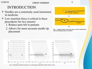
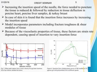
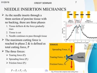
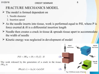
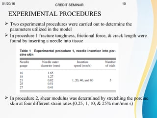
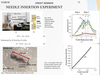
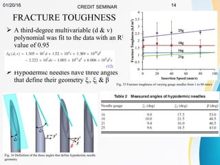
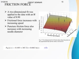
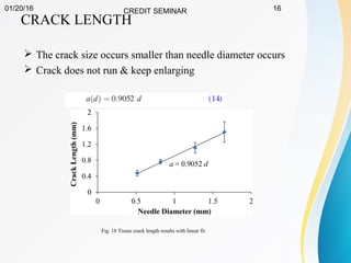
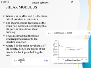
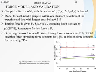
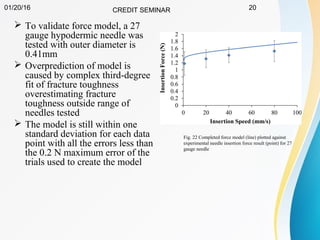
01/20/1601/20/16 CREDITCREDIT SEMINARSEMINAR 11
FRACTURE MECHANICS MODEL OF
NEEDLE CUTTING TISSUE
SUBMITTED BY
NAME: NEHEM TUDU
ROLL NO.: M150360ME
MANUFACTURING TECHNOLOGY
01/20/16 CREDIT SEMINAR 2
CONTENTS
Introduction
Needle Manufacturing Process
Needle Insertion Mechanics
Experimental Procedures
Results and Discussion
Force Model and Validation
Conclusions
Reference
01/20/16 CREDIT SEMINAR 3
INTRODUCTION
 Needles are a commonly used instrument
in medicine
 Low insertion force is critical in these
procedures for two reasons:
1. Reduce pain felt in patients
2. Allows for more accurate needle tip
placement
Fig. 2 Simulated needle intercept of a small target embedded within elastic tissue.
01/20/16 CREDIT SEMINAR 4
 Insertion force of needle can be reduce by altering tip & reducing the
gauge size
 But microneedle cannot be used in all procedure
 Force can be reduced by applying vibratory actuator & can be
controlled precisely
How to reduce insertion force ?
Fig.4 Graph of skin penetration force from excized animal tissue showing a
greater than 70% reduction in insertion force using the vibratory actuator
Fig. 3 Different needle tips
01/20/16 CREDIT SEMINAR 5
 Increasing the insertion speed of the needle, the force needed to puncture
the tissue is reduced & followed by reduction in tissue deflection in
porcine heart, porcine liver samples, & turkey breast
 In case of skin it is found that the insertion force increases by increasing
the insertion speed
 Model incorporates parameters including fracture toughness & shear
modulus of tissue
 Because of the viscoelastic properties of tissue, these factors are strain rate
dependent, causing speed of insertion to vary insertion force
Fig. 5. Mean peak rupture force versus velocity for pig heart insertion.
Error bars denote standard deviation.
Figure 6. Insertion force–displacement curves of 30G needles in 3%
agarose gel with polyurethane foil at different speeds.
01/20/16 CREDIT SEMINAR 6
NEEDLE MANUFACTURING PROCESS
Rolling of metal sheet Drawing process of needle
Cutting of needle
Grinding of needle
Fixed to needle hub
01/20/16 CREDIT SEMINAR 7
NEEDLE INSERTION MECHANICS
 As the needle inserts through a
4mm section of porcine tissue with
no backing, there are three phases
1. Tissue deflects & the force gradually
rises
2. Tissue is cut
3. Needle continues to pass through tissue
 The maximum cutting force is
reached in phase 2 & is defined as
total cutting force, P
 The three forces:
 Tearing force (Pt)
 Spreading force (PS)
 Friction force (PF)
Fig. 7 Force profile
of needle passing
through porcine skin
Fig. 8 Forces that compose total cutting force
01/20/16 CREDIT SEMINAR 8
FRACTURE MECHANICS MODEL
 The model is formed dependent on
1. Needle diameter
2. Insertion speed
 As the needle inserts into tissue, work is performed equal to Pδl, where P is
force exerted & δl is a differential insertion length
 Needle then creates a crack in tissue & spreads tissue apart to accommodate
the width of needle
 Kinetic energy was neglected in development of model
Fig. 9 Different mode of fracture
01/20/16 CREDIT SEMINAR 9
 Crack around the needle is not completely circular because of this, a non-
dimensional contact factor f(d) needs to be added into the δ termɅ
 Goal of this work is to be able to describe maximum insertion force of
needle into tissue
 Friction occurring at maximum insertion force is puncture friction force PFP
 Where μ is the shear modulus
01/20/16 CREDIT SEMINAR 10
EXPERIMENTAL PROCEDURES
 Two experimental procedures were carried out to determine the
parameters utilized in the model
 In procedure 1 fracture toughness, frictional force, & crack length were
found by inserting a needle into tissue
 In procedure 2, shear modulus was determined by stretching the porcine
skin at four different strain rates (0.25, 1, 10, & 25% mm/mm s)
01/20/16 CREDIT SEMINAR 11
NEEDLE INSERTION EXPERIMENT
Fig. 10 (a)
Experimental
setup for needle
insertion and
(b) porcine
skin mounting
Fig. 11 (a) Graph of first and
second needle insertion and
(b) graph of fracture work
performed to determine JIC
Fig. 12 Measured needle crack length in porcine skin
01/20/16 CREDIT SEMINAR 12
TISSUE TENSION EXPERIMENT
 Results of this experiment were analyzed with
an Ogden model
 Porcine skin is viscoelastic and anisotropic
 Young’s modulus of the tissue is low to begin
because the collagen fibers are moving about
each other
 At higher strains, the fibers become aligned and
the tissue stiffens
 where is the strain energy density, μ is theϕ
shear modulus, α is the strain hardening, λiare
the principle stretch ratios, σz is the stress & λz is
stretch ratio in the pull direction
Fig. 13 Experimental setup for stretching porcine skin to determine
shear modulus
Fig. 14 Stress–strain curve of the porcine skin parallel, at a 45 deg angle,
and perpendicular (including Ogden Fit) to the Langer lines
01/20/16 CREDIT SEMINAR 13
RESULT
Needle
insertion
experiment
Tissue
tension
experiment
Contact
factor
Shear
Modulus
Fracture
toughness
Frictional
force
Crack
length
01/20/16 CREDIT SEMINAR 14
FRACTURE TOUGHNESS
 A third-degree multivariable (d & v)
polynomial was fit to the data with an R2
value of 0.95
 Hypodermic needles have three angles
that define their geometry ξ1, ξ2 & β
Fig. 16 Definition of the three angles that define hypodermic needle
geometry
Fig. 15 Fracture toughness of varying gauge needles from 1 to 80 mm/s
01/20/16 CREDIT SEMINAR 15
FRICTION FORCE
 A two-dimensional fit was
applied to the data with an R2
value of 0.90
 Frictional force increases with
increasing speed
 Puncture friction force also
increases with increasing
needle diameter
Fig. 17 Two-dimensional fit of friction data where the points are
the experimental data and the surface is the best fit
01/20/16 CREDIT SEMINAR 16
CRACK LENGTH
 The crack size occurs smaller than needle diameter occurs
 Crack does not run & keep enlarging
Fig. 18 Tissue crack length results with linear fit
01/20/16 CREDIT SEMINAR 17
SHEAR MODULUS
 Where μ is in MPa, and έ is the strain
rate of insertion in mm/mm s
 The shear modulus decreased as the
strain rate increased, confirming that
the porcine skin shows shear
thinning
 It was assumed that the tissue
strained perpendicular to the
insertion direction
 Where β is the major bevel angle of
the needle, & RS is the radius of the
hole in the back plate holding the
skin
Fig. 19 Measured shear modulus compared to strain rate
01/20/16 CREDIT SEMINAR 18
CONTACT FACTOR
 Contact factor f was found by fitting insertion force model, to
experimental force results
 Contact factor was found for each needle gauge size separately using a
best fit least-squares regression
Fig. 20 Contact factor f compared to needle outer diameter
01/20/16 CREDIT SEMINAR 19
FORCE MODEL AND VALIDATION
 Completed force model, with the values of JIC(d,v), & PFP(d,v) is formed
 Model for each needle gauge is within one standard deviation of the
experimental data with largest error being 0.2 N
 Tearing force is given by JIC(d,v)a(d), spreading force is given by
μ(v)R2
f(d), & puncture friction force is PFP
 On average across four needle sizes, tearing force accounts for 61% of total
insertion force, spreading force accounts for 18%, & friction force accounts
for remaining 21%
Fig. 21 Completed force model (lines) plotted against
experimental needle insertion force results (points)
01/20/16 CREDIT SEMINAR 20
 To validate force model, a 27
gauge hypodermic needle was
tested with outer diameter is
0.41mm
 Overprediction of model is
caused by complex third-degree
fit of fracture toughness
overestimating fracture
toughness outside range of
needles tested
 The model is still within one
standard deviation for each data
point with all the errors less than
the 0.2 N maximum error of the
trials used to create the model
Fig. 22 Completed force model (line) plotted against
experimental needle insertion force result (point) for 27
gauge needle
01/20/16 CREDIT SEMINAR 21
CONCLUSION
 A dynamic physics-based model was constructed & shown to accurately
predict insertion forces upon needle insertion into porcine skin for four
different gauge hypodermic needles
 Model shows that on average 61% of the total insertion force comes from
creating the crack, friction contributes 21% of the total force & the
spreading of the tissue contributes 18% of the force
 For porcine skin, increasing the insertion speed did not lower the insertion
force
 Fracture toughness is relatively constant across different insertion speeds
 Increasing insertion speed increases the frictional force on the needle
 Increasing speeds were shown to benefit in reducing the spreading force
of the tissue to accommodate the needle
01/20/16 CREDIT SEMINAR 22
REFERENCE
 Dimaio, S. P., and Salcudean, S. E., 2003, “Needle Insertion Modeling and
Simulation,” IEEE Trans. Rob. Autom., 19(5), pp. 864–875.
 Ehmann, K., and Malukhin, K., 2012, “A Generalized Analytical Model of the
Cutting Angles of a Biopsy Needle Tip,” ASME J. Manuf. Sci. Eng., 134(6), p.
061001.
 Yang, M., and Zahn, J. D., 2004, “Microneedle Insertion Force Reduction Using
Vibratory Actuation,” Biomed. Microdevices, 6(3), pp. 177–182.
 Mahvash, M., and Dupont, P. E., 2010, “Mechanics of Dynamic Needle Insertion
into a Biological Material,” IEEE Trans. Biomed. Eng., 57(4), pp. 934–943.
 Ogden, R. W., Saccomandi, G., and Sgura, I., 2004, “Fitting Hyperelastic Models
to Experimental Data,” Comput. Mech., 34(6), pp. 484–502.
 Koelmans, W., Krishnamoorthy, G., Heskamp, A., Wissink, J., Misra, S., and
Tas, N., 2013, “Microneedle Characterization Using a Double-Layer Skin
Simulant,” Mech. Eng. Res., 3(2), pp. 51–63.
 Cuppoletti, J., 2011, Nanocomposites with Unique Properties and
Applications in Medicine and Industry, InTech, CC BY-NC-SA 3.0 license
01/20/16 CREDIT SEMINAR 23
THANK YOU

Fracture mechanics

  • 1.
    01/20/1601/20/16 CREDITCREDIT SEMINARSEMINAR11 FRACTURE MECHANICS MODEL OF NEEDLE CUTTING TISSUE SUBMITTED BY NAME: NEHEM TUDU ROLL NO.: M150360ME MANUFACTURING TECHNOLOGY
  • 2.
    01/20/16 CREDIT SEMINAR2 CONTENTS Introduction Needle Manufacturing Process Needle Insertion Mechanics Experimental Procedures Results and Discussion Force Model and Validation Conclusions Reference
  • 3.
    01/20/16 CREDIT SEMINAR3 INTRODUCTION  Needles are a commonly used instrument in medicine  Low insertion force is critical in these procedures for two reasons: 1. Reduce pain felt in patients 2. Allows for more accurate needle tip placement Fig. 2 Simulated needle intercept of a small target embedded within elastic tissue.
  • 4.
    01/20/16 CREDIT SEMINAR4  Insertion force of needle can be reduce by altering tip & reducing the gauge size  But microneedle cannot be used in all procedure  Force can be reduced by applying vibratory actuator & can be controlled precisely How to reduce insertion force ? Fig.4 Graph of skin penetration force from excized animal tissue showing a greater than 70% reduction in insertion force using the vibratory actuator Fig. 3 Different needle tips
  • 5.
    01/20/16 CREDIT SEMINAR5  Increasing the insertion speed of the needle, the force needed to puncture the tissue is reduced & followed by reduction in tissue deflection in porcine heart, porcine liver samples, & turkey breast  In case of skin it is found that the insertion force increases by increasing the insertion speed  Model incorporates parameters including fracture toughness & shear modulus of tissue  Because of the viscoelastic properties of tissue, these factors are strain rate dependent, causing speed of insertion to vary insertion force Fig. 5. Mean peak rupture force versus velocity for pig heart insertion. Error bars denote standard deviation. Figure 6. Insertion force–displacement curves of 30G needles in 3% agarose gel with polyurethane foil at different speeds.
  • 6.
    01/20/16 CREDIT SEMINAR6 NEEDLE MANUFACTURING PROCESS Rolling of metal sheet Drawing process of needle Cutting of needle Grinding of needle Fixed to needle hub
  • 7.
    01/20/16 CREDIT SEMINAR7 NEEDLE INSERTION MECHANICS  As the needle inserts through a 4mm section of porcine tissue with no backing, there are three phases 1. Tissue deflects & the force gradually rises 2. Tissue is cut 3. Needle continues to pass through tissue  The maximum cutting force is reached in phase 2 & is defined as total cutting force, P  The three forces:  Tearing force (Pt)  Spreading force (PS)  Friction force (PF) Fig. 7 Force profile of needle passing through porcine skin Fig. 8 Forces that compose total cutting force
  • 8.
    01/20/16 CREDIT SEMINAR8 FRACTURE MECHANICS MODEL  The model is formed dependent on 1. Needle diameter 2. Insertion speed  As the needle inserts into tissue, work is performed equal to Pδl, where P is force exerted & δl is a differential insertion length  Needle then creates a crack in tissue & spreads tissue apart to accommodate the width of needle  Kinetic energy was neglected in development of model Fig. 9 Different mode of fracture
  • 9.
    01/20/16 CREDIT SEMINAR9  Crack around the needle is not completely circular because of this, a non- dimensional contact factor f(d) needs to be added into the δ termɅ  Goal of this work is to be able to describe maximum insertion force of needle into tissue  Friction occurring at maximum insertion force is puncture friction force PFP  Where μ is the shear modulus
  • 10.
    01/20/16 CREDIT SEMINAR10 EXPERIMENTAL PROCEDURES  Two experimental procedures were carried out to determine the parameters utilized in the model  In procedure 1 fracture toughness, frictional force, & crack length were found by inserting a needle into tissue  In procedure 2, shear modulus was determined by stretching the porcine skin at four different strain rates (0.25, 1, 10, & 25% mm/mm s)
  • 11.
    01/20/16 CREDIT SEMINAR11 NEEDLE INSERTION EXPERIMENT Fig. 10 (a) Experimental setup for needle insertion and (b) porcine skin mounting Fig. 11 (a) Graph of first and second needle insertion and (b) graph of fracture work performed to determine JIC Fig. 12 Measured needle crack length in porcine skin
  • 12.
    01/20/16 CREDIT SEMINAR12 TISSUE TENSION EXPERIMENT  Results of this experiment were analyzed with an Ogden model  Porcine skin is viscoelastic and anisotropic  Young’s modulus of the tissue is low to begin because the collagen fibers are moving about each other  At higher strains, the fibers become aligned and the tissue stiffens  where is the strain energy density, μ is theϕ shear modulus, α is the strain hardening, λiare the principle stretch ratios, σz is the stress & λz is stretch ratio in the pull direction Fig. 13 Experimental setup for stretching porcine skin to determine shear modulus Fig. 14 Stress–strain curve of the porcine skin parallel, at a 45 deg angle, and perpendicular (including Ogden Fit) to the Langer lines
  • 13.
    01/20/16 CREDIT SEMINAR13 RESULT Needle insertion experiment Tissue tension experiment Contact factor Shear Modulus Fracture toughness Frictional force Crack length
  • 14.
    01/20/16 CREDIT SEMINAR14 FRACTURE TOUGHNESS  A third-degree multivariable (d & v) polynomial was fit to the data with an R2 value of 0.95  Hypodermic needles have three angles that define their geometry ξ1, ξ2 & β Fig. 16 Definition of the three angles that define hypodermic needle geometry Fig. 15 Fracture toughness of varying gauge needles from 1 to 80 mm/s
  • 15.
    01/20/16 CREDIT SEMINAR15 FRICTION FORCE  A two-dimensional fit was applied to the data with an R2 value of 0.90  Frictional force increases with increasing speed  Puncture friction force also increases with increasing needle diameter Fig. 17 Two-dimensional fit of friction data where the points are the experimental data and the surface is the best fit
  • 16.
    01/20/16 CREDIT SEMINAR16 CRACK LENGTH  The crack size occurs smaller than needle diameter occurs  Crack does not run & keep enlarging Fig. 18 Tissue crack length results with linear fit
  • 17.
    01/20/16 CREDIT SEMINAR17 SHEAR MODULUS  Where μ is in MPa, and έ is the strain rate of insertion in mm/mm s  The shear modulus decreased as the strain rate increased, confirming that the porcine skin shows shear thinning  It was assumed that the tissue strained perpendicular to the insertion direction  Where β is the major bevel angle of the needle, & RS is the radius of the hole in the back plate holding the skin Fig. 19 Measured shear modulus compared to strain rate
  • 18.
    01/20/16 CREDIT SEMINAR18 CONTACT FACTOR  Contact factor f was found by fitting insertion force model, to experimental force results  Contact factor was found for each needle gauge size separately using a best fit least-squares regression Fig. 20 Contact factor f compared to needle outer diameter
  • 19.
    01/20/16 CREDIT SEMINAR19 FORCE MODEL AND VALIDATION  Completed force model, with the values of JIC(d,v), & PFP(d,v) is formed  Model for each needle gauge is within one standard deviation of the experimental data with largest error being 0.2 N  Tearing force is given by JIC(d,v)a(d), spreading force is given by μ(v)R2 f(d), & puncture friction force is PFP  On average across four needle sizes, tearing force accounts for 61% of total insertion force, spreading force accounts for 18%, & friction force accounts for remaining 21% Fig. 21 Completed force model (lines) plotted against experimental needle insertion force results (points)
  • 20.
    01/20/16 CREDIT SEMINAR20  To validate force model, a 27 gauge hypodermic needle was tested with outer diameter is 0.41mm  Overprediction of model is caused by complex third-degree fit of fracture toughness overestimating fracture toughness outside range of needles tested  The model is still within one standard deviation for each data point with all the errors less than the 0.2 N maximum error of the trials used to create the model Fig. 22 Completed force model (line) plotted against experimental needle insertion force result (point) for 27 gauge needle
  • 21.
    01/20/16 CREDIT SEMINAR21 CONCLUSION  A dynamic physics-based model was constructed & shown to accurately predict insertion forces upon needle insertion into porcine skin for four different gauge hypodermic needles  Model shows that on average 61% of the total insertion force comes from creating the crack, friction contributes 21% of the total force & the spreading of the tissue contributes 18% of the force  For porcine skin, increasing the insertion speed did not lower the insertion force  Fracture toughness is relatively constant across different insertion speeds  Increasing insertion speed increases the frictional force on the needle  Increasing speeds were shown to benefit in reducing the spreading force of the tissue to accommodate the needle
  • 22.
    01/20/16 CREDIT SEMINAR22 REFERENCE  Dimaio, S. P., and Salcudean, S. E., 2003, “Needle Insertion Modeling and Simulation,” IEEE Trans. Rob. Autom., 19(5), pp. 864–875.  Ehmann, K., and Malukhin, K., 2012, “A Generalized Analytical Model of the Cutting Angles of a Biopsy Needle Tip,” ASME J. Manuf. Sci. Eng., 134(6), p. 061001.  Yang, M., and Zahn, J. D., 2004, “Microneedle Insertion Force Reduction Using Vibratory Actuation,” Biomed. Microdevices, 6(3), pp. 177–182.  Mahvash, M., and Dupont, P. E., 2010, “Mechanics of Dynamic Needle Insertion into a Biological Material,” IEEE Trans. Biomed. Eng., 57(4), pp. 934–943.  Ogden, R. W., Saccomandi, G., and Sgura, I., 2004, “Fitting Hyperelastic Models to Experimental Data,” Comput. Mech., 34(6), pp. 484–502.  Koelmans, W., Krishnamoorthy, G., Heskamp, A., Wissink, J., Misra, S., and Tas, N., 2013, “Microneedle Characterization Using a Double-Layer Skin Simulant,” Mech. Eng. Res., 3(2), pp. 51–63.  Cuppoletti, J., 2011, Nanocomposites with Unique Properties and Applications in Medicine and Industry, InTech, CC BY-NC-SA 3.0 license
  • 23.