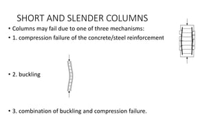
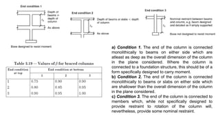
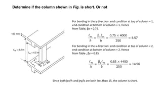
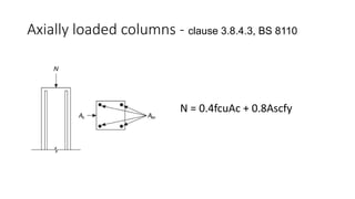
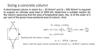
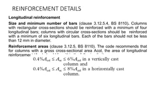
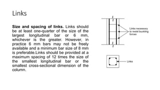
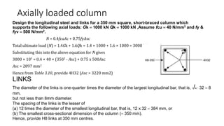
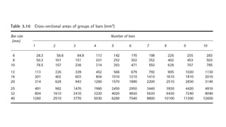
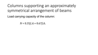
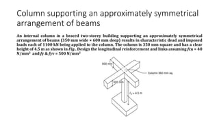
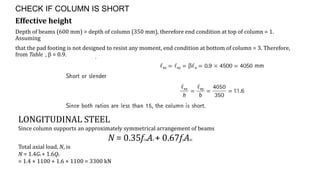
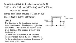
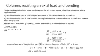
Column
SHORT AND SLENDER COLUMNS
• Columns may fail due to one of three mechanisms:
• 1. compression failure of the concrete/steel reinforcement
• 2. buckling
• 3. combination of buckling and compression failure.
SHORT BRACED COLUMN DESIGN
1. columns resisting axial loads only;
2. columns supporting an approximately symmetrical arrangement of
beams;
3. columns resisting axial loads and uniaxial or biaxial bending.
BS 8110 classifies a column as being short if
a) Condition 1. The end of the column is connected
monolithically to beams on either side which are
atleast as deep as the overall dimension of the column
in the plane considered. Where the column is
connected to a foundation structure, this should be of a
form specifically designed to carry moment.
b) Condition 2. The end of the column is connected
monolithically to beams or slabs on either side which
are shallower than the overall dimension of the column
in the plane considered.
c) Condition 3. The end of the column is connected to
members which, while not specifically designed to
provide restraint to rotation of the column will,
nevertheless, provide some nominal restraint.
Determine if the column shown in Fig. is short. Or not
For bending in the y direction: end condition at top of column = 1,
end condition at bottom of column = 1. Hence
from Table, βx = 0.75.
For bending in the x direction: end condition at top of column = 2,
end condition at bottom of column = 2. Hence
from Table , βy = 0.85
Since both ɭex/h and ɭey/b are both less than 15, the column is short.
Axially loaded columns - clause 3.8.4.3, BS 8110
N = 0.4fcuAc + 0.8Ascfy
Sizing a concrete column
A short-braced column in which fcu = 30 N/mm2 and fy = 500 N/mm2 is required
to support an ultimate axial load of 2000 kN. Determine a suitable section for
the column assuming that the area of longitudinal steel, Asc, is of the order of 3
per cent of the gross cross-sectional area of column, Acol.
REINFORCEMENT DETAILS
Longitudinal reinforcement
Size and minimum number of bars (clause 3.12.5.4, BS 8110). Columns
with rectangular cross-sections should be reinforced with a minimum of four
longitudinal bars; columns with circular cross-sections should be reinforced
with a minimum of six longitudinal bars. Each of the bars should not be less
than 12 mm in diameter.
Reinforcement areas (clause 3.12.5, BS 8110). The code recommends that
for columns with a gross cross-sectional area Acol, the area of longitudinal
reinforcement (Asc) should lie within the following limits:
Links
Size and spacing of links. Links should
be at least one-quarter of the size of the
largest longitudinal bar or 6 mm,
whichever is the greater. However, in
practice 6 mm bars may not be freely
available and a minimum bar size of 8 mm
is preferable.Links should be provided at a
maximum spacing of 12 times the size of
the smallest longitudinal bar or the
smallest cross-sectional dimension of the
column.
Axially loaded column
Design the longitudinal steel and links for a 350 mm square, short-braced column which
supports the following axial loads: Gk = 1000 kN Qk = 1000 kN ,Assume fcu = 40 N/mm2 and fy &
fyv = 500 N/mm2.
N = 0.4fcuAc + 0.75fyAsc
Total ultimate load (N) = 1.4Gk + 1.6Qk = 1.4 × 1000 + 1.6 × 1000 = 3000 kN
Substituting this into the above equation for N gives
3000 × 103 = 0.4 × 40 × (3502 - Asc) + 0.75 x 500Asc
Asc = 2897 mm2
Hence from Table 3.10, provide 4H32 (Asc = 3220 mm2)
LINKS
The diameter of the links is one-quarter times the diameter of the largest longitudinal bar, that is, 1/4  32 = 8
mm,
but not less than 8mm diameter.
The spacing of the links is the lesser of
(a) 12 times the diameter of the smallest longitudinal bar, that is, 12 x 32 = 384 mm, or
(b) The smallest cross-sectional dimension of the column (= 350 mm).
Hence, provide H8 links at 350 mm centres.
Columns supporting an approximately
symmetrical arrangement of beams
Load carrying capacity of the column:
N = 0.35fcuAc + 0.67fyAsc
Column supporting an approximately symmetrical
arrangement of beams
An internal column in a braced two-storey building supporting an approximately symmetrical
arrangement of beams (350 mm wide × 600 mm deep) results in characteristic dead and imposed
loads each of 1100 kN being applied to the column. The column is 350 mm square and has a clear
height of 4.5 m as shown in Fig.. Design the longitudinal reinforcement and links assuming fcu = 40
N/mm2 and fy & fyv = 500 N/mm2
CHECK IF COLUMN IS SHORT
Effective height
Depth of beams (600 mm) > depth of column (350 mm), therefore end condition at top of column = 1.
Assuming
that the pad footing is not designed to resist any moment, end condition at bottom of column = 3. Therefore,
from Table ,  = 0.9.
LONGITUDINAL STEEL
Since column supports an approximately symmetrical arrangement of beams
N = 0.35fcuAc + 0.67fyAsc
Total axial load, N, is
N = 1.4Gk + 1.6Qk
= 1.4 × 1100 + 1.6 × 1100 = 3300 kN
Substituting this into the above equation for N
3300 × 103 = 0.35 × 40(3502 − Asc) + 0.67 × 500Asc
⇒ Asc = 4938 mm2
Hence from Table, provide 4H32 and 4H25
(Asc = 3220 + 1960 = 5180 mm2)
LINKS
The diameter of the links is one-quarter
times the diameter of the largest longitudinal
bar, that is 1/4  32 = 8 mm, but not less than
8mm diameter. The spacing of the links is
the lesser of
(a) 12 times the diameter of the smallest
longitudinal bar, that is, 12  25 = 300 mm, or
(b) the smallest cross-sectional dimension of
the column (= 350 mm).
Columns resisting an axial load and bending
Design the longitudinal and shear reinforcement for a 275 mm square, short-braced column which
supports either
(a) an ultimate axial load of 1280 kN and a moment of 62.5 kNm about the x–x axis or
(b) an ultimate axial load of 1280 kN and bending moments of 35 kNm about the x–x axis and 25 kNm
about the y–y axis.
Assume fcu = 30 N/mm2, fy = 500 30 N/mm2 and cover to all reinforcement is 35 mm.
LOAD CASE (A)
Longitudinal steel
100Asc/bh = 3,
Asc = 3 x 275 × 275/100 = 2269 mm2
Provide 8H20 (Asc = 2510mm2, Table)
Links
The diameter of the links is one-quarter
times the diameter of the largest
longitudinal bar, that is, 1/4  20 = 5 mm,
but not less than 8 mm diameter. The
spacing of the links is the lesser of
(a) 12 times the diameter of the smallest
longitudinal bar, that is, 12  20 = 240 mm,
or (b) the smallest cross-sectional
dimension of the column (= 275 mm).
Provide H8 links at 240 mm centres
• LOAD CASE (B)
• Longitudinal steel

Column uniaxial axial loaded column design

  • 1.
  • 2.
    SHORT AND SLENDERCOLUMNS • Columns may fail due to one of three mechanisms: • 1. compression failure of the concrete/steel reinforcement • 2. buckling • 3. combination of buckling and compression failure.
  • 3.
    SHORT BRACED COLUMNDESIGN 1. columns resisting axial loads only; 2. columns supporting an approximately symmetrical arrangement of beams; 3. columns resisting axial loads and uniaxial or biaxial bending.
  • 4.
    BS 8110 classifiesa column as being short if
  • 5.
    a) Condition 1.The end of the column is connected monolithically to beams on either side which are atleast as deep as the overall dimension of the column in the plane considered. Where the column is connected to a foundation structure, this should be of a form specifically designed to carry moment. b) Condition 2. The end of the column is connected monolithically to beams or slabs on either side which are shallower than the overall dimension of the column in the plane considered. c) Condition 3. The end of the column is connected to members which, while not specifically designed to provide restraint to rotation of the column will, nevertheless, provide some nominal restraint.
  • 6.
    Determine if thecolumn shown in Fig. is short. Or not For bending in the y direction: end condition at top of column = 1, end condition at bottom of column = 1. Hence from Table, βx = 0.75. For bending in the x direction: end condition at top of column = 2, end condition at bottom of column = 2. Hence from Table , βy = 0.85 Since both ɭex/h and ɭey/b are both less than 15, the column is short.
  • 7.
    Axially loaded columns- clause 3.8.4.3, BS 8110 N = 0.4fcuAc + 0.8Ascfy
  • 8.
    Sizing a concretecolumn A short-braced column in which fcu = 30 N/mm2 and fy = 500 N/mm2 is required to support an ultimate axial load of 2000 kN. Determine a suitable section for the column assuming that the area of longitudinal steel, Asc, is of the order of 3 per cent of the gross cross-sectional area of column, Acol.
  • 9.
    REINFORCEMENT DETAILS Longitudinal reinforcement Sizeand minimum number of bars (clause 3.12.5.4, BS 8110). Columns with rectangular cross-sections should be reinforced with a minimum of four longitudinal bars; columns with circular cross-sections should be reinforced with a minimum of six longitudinal bars. Each of the bars should not be less than 12 mm in diameter. Reinforcement areas (clause 3.12.5, BS 8110). The code recommends that for columns with a gross cross-sectional area Acol, the area of longitudinal reinforcement (Asc) should lie within the following limits:
  • 10.
    Links Size and spacingof links. Links should be at least one-quarter of the size of the largest longitudinal bar or 6 mm, whichever is the greater. However, in practice 6 mm bars may not be freely available and a minimum bar size of 8 mm is preferable.Links should be provided at a maximum spacing of 12 times the size of the smallest longitudinal bar or the smallest cross-sectional dimension of the column.
  • 11.
    Axially loaded column Designthe longitudinal steel and links for a 350 mm square, short-braced column which supports the following axial loads: Gk = 1000 kN Qk = 1000 kN ,Assume fcu = 40 N/mm2 and fy & fyv = 500 N/mm2. N = 0.4fcuAc + 0.75fyAsc Total ultimate load (N) = 1.4Gk + 1.6Qk = 1.4 × 1000 + 1.6 × 1000 = 3000 kN Substituting this into the above equation for N gives 3000 × 103 = 0.4 × 40 × (3502 - Asc) + 0.75 x 500Asc Asc = 2897 mm2 Hence from Table 3.10, provide 4H32 (Asc = 3220 mm2) LINKS The diameter of the links is one-quarter times the diameter of the largest longitudinal bar, that is, 1/4  32 = 8 mm, but not less than 8mm diameter. The spacing of the links is the lesser of (a) 12 times the diameter of the smallest longitudinal bar, that is, 12 x 32 = 384 mm, or (b) The smallest cross-sectional dimension of the column (= 350 mm). Hence, provide H8 links at 350 mm centres.
  • 13.
    Columns supporting anapproximately symmetrical arrangement of beams Load carrying capacity of the column: N = 0.35fcuAc + 0.67fyAsc
  • 14.
    Column supporting anapproximately symmetrical arrangement of beams An internal column in a braced two-storey building supporting an approximately symmetrical arrangement of beams (350 mm wide × 600 mm deep) results in characteristic dead and imposed loads each of 1100 kN being applied to the column. The column is 350 mm square and has a clear height of 4.5 m as shown in Fig.. Design the longitudinal reinforcement and links assuming fcu = 40 N/mm2 and fy & fyv = 500 N/mm2
  • 15.
    CHECK IF COLUMNIS SHORT Effective height Depth of beams (600 mm) > depth of column (350 mm), therefore end condition at top of column = 1. Assuming that the pad footing is not designed to resist any moment, end condition at bottom of column = 3. Therefore, from Table ,  = 0.9. LONGITUDINAL STEEL Since column supports an approximately symmetrical arrangement of beams N = 0.35fcuAc + 0.67fyAsc Total axial load, N, is N = 1.4Gk + 1.6Qk = 1.4 × 1100 + 1.6 × 1100 = 3300 kN
  • 16.
    Substituting this intothe above equation for N 3300 × 103 = 0.35 × 40(3502 − Asc) + 0.67 × 500Asc ⇒ Asc = 4938 mm2 Hence from Table, provide 4H32 and 4H25 (Asc = 3220 + 1960 = 5180 mm2) LINKS The diameter of the links is one-quarter times the diameter of the largest longitudinal bar, that is 1/4  32 = 8 mm, but not less than 8mm diameter. The spacing of the links is the lesser of (a) 12 times the diameter of the smallest longitudinal bar, that is, 12  25 = 300 mm, or (b) the smallest cross-sectional dimension of the column (= 350 mm).
  • 17.
    Columns resisting anaxial load and bending Design the longitudinal and shear reinforcement for a 275 mm square, short-braced column which supports either (a) an ultimate axial load of 1280 kN and a moment of 62.5 kNm about the x–x axis or (b) an ultimate axial load of 1280 kN and bending moments of 35 kNm about the x–x axis and 25 kNm about the y–y axis. Assume fcu = 30 N/mm2, fy = 500 30 N/mm2 and cover to all reinforcement is 35 mm. LOAD CASE (A) Longitudinal steel
  • 19.
    100Asc/bh = 3, Asc= 3 x 275 × 275/100 = 2269 mm2 Provide 8H20 (Asc = 2510mm2, Table) Links The diameter of the links is one-quarter times the diameter of the largest longitudinal bar, that is, 1/4  20 = 5 mm, but not less than 8 mm diameter. The spacing of the links is the lesser of (a) 12 times the diameter of the smallest longitudinal bar, that is, 12  20 = 240 mm, or (b) the smallest cross-sectional dimension of the column (= 275 mm). Provide H8 links at 240 mm centres
  • 20.
    • LOAD CASE(B) • Longitudinal steel