Downloaded 61 times


![Chapter 2. Before Configuring a Red Hat Cluster
may vary among computers. However, the objective of this procedure is to
configure the BIOS so that the computer is turned off via the power button
without delay.
4. Exit the BIOS CMOS Setup Utility program, saving the BIOS configuration.
5. When the cluster is configured and running, verify that the node turns off immediately when
fenced.
Tip
You can fence the node with the fence_node command or Conga.
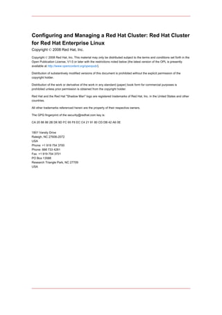
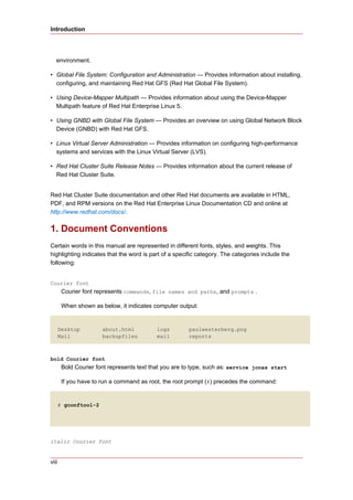
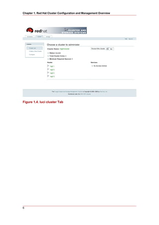
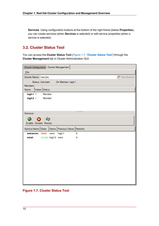
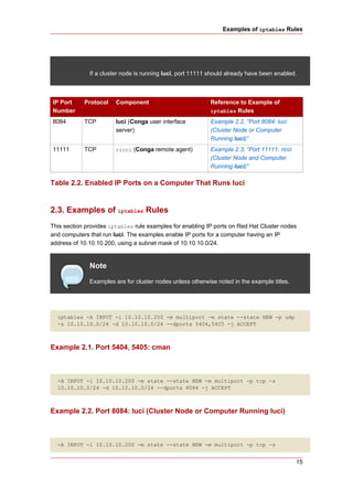
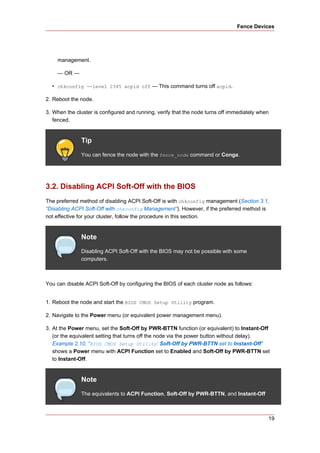
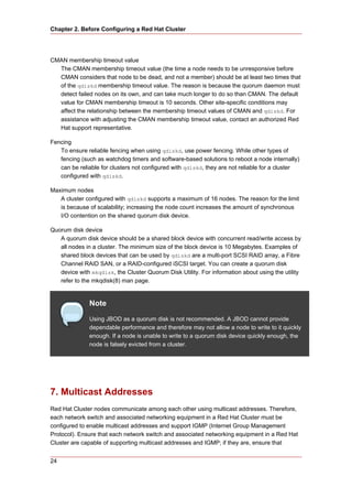
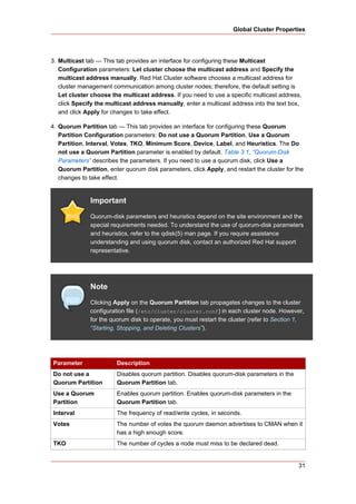
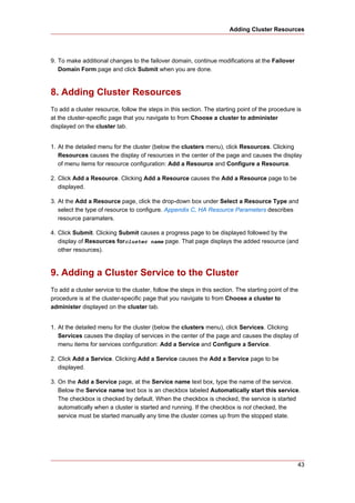
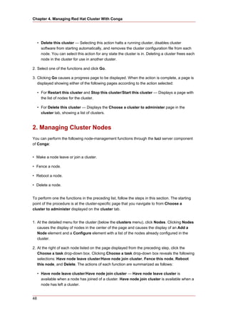
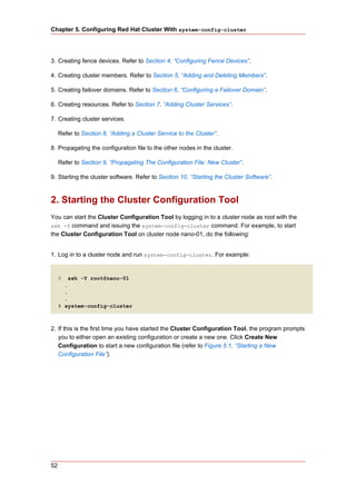
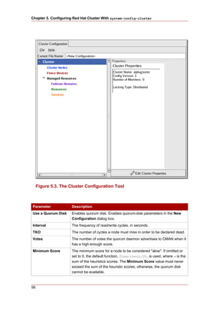
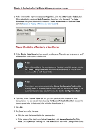
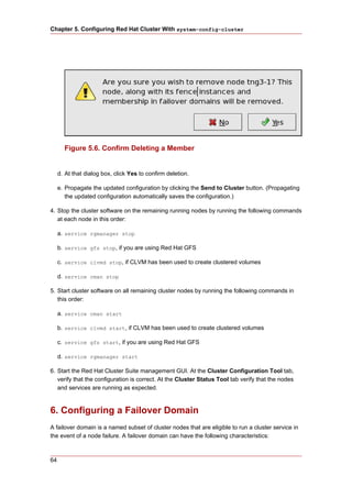
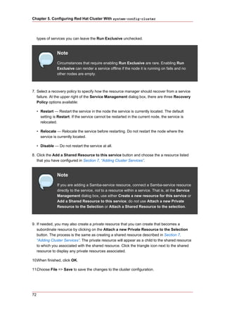
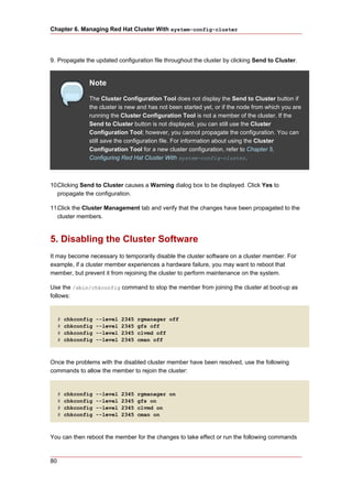
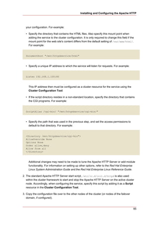
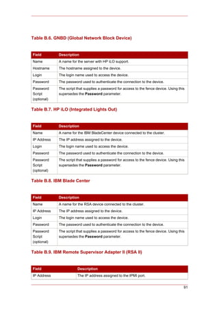
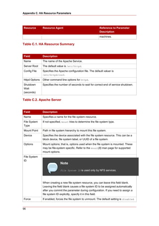
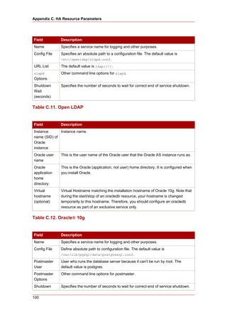
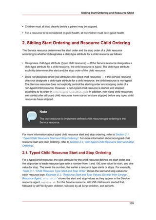
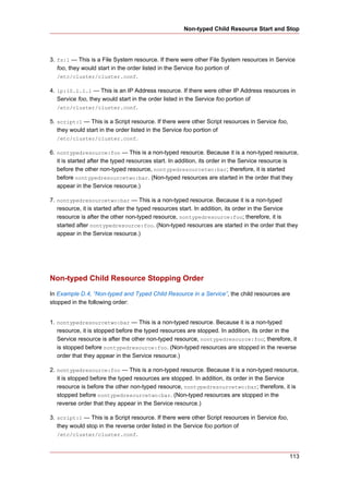
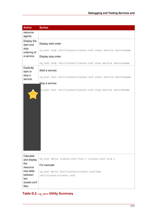
+-------------------------------------------------|------------------------+
| ACPI Function [Enabled] | Item Help |
| ACPI Suspend Type [S1(POS)] |------------------------|
| x Run VGABIOS if S3 Resume Auto | Menu Level * |
| Suspend Mode [Disabled] | |
| HDD Power Down [Disabled] | |
| Soft-Off by PWR-BTTN [Instant-Off] | |
| CPU THRM-Throttling [50.0%] | |
| Wake-Up by PCI card [Enabled] | |
| Power On by Ring [Enabled] | |
| Wake Up On LAN [Enabled] | |
| x USB KB Wake-Up From S3 Disabled | |
| Resume by Alarm [Disabled] | |
| x Date(of Month) Alarm 0 | |
| x Time(hh:mm:ss) Alarm 0 : 0 : 0 | |
| POWER ON Function [BUTTON ONLY] | |
| x KB Power ON Password Enter | |
| x Hot Key Power ON Ctrl-F1 | |
| | |
| | |
+-------------------------------------------------|------------------------+
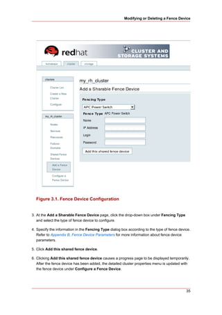
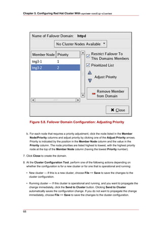
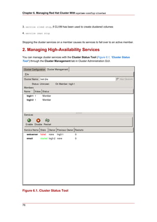
This example shows ACPI Function set to Enabled, and Soft-Off by PWR-BTTN set to
Instant-Off.
Example 2.10. BIOS CMOS Setup Utility: Soft-Off by PWR-BTTN set to
Instant-Off
20](https://image.slidesharecdn.com/clusterinlinux-121103082755-phpapp01/85/Cluster-in-linux-30-320.jpg)

![Chapter 3. Configuring Red Hat Cluster With Conga
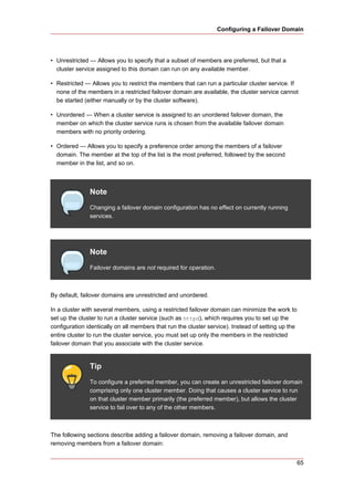
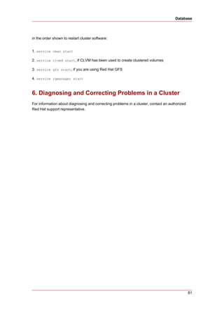
2. Starting luci and ricci
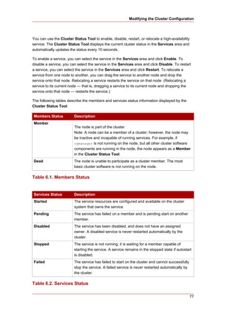
To administer Red Hat Clusters with Conga, install and run luci and ricci as follows:
1. At each node to be administered by Conga, install the ricci agent. For example:
# yum install ricci
2. At each node to be administered by Conga, start ricci. For example:
# service ricci start
Starting ricci: [ OK ]
3. Select a computer to host luci and install the luci software on that computer. For example:
# yum install luci
Note
Typically, a computer in a server cage or a data center hosts luci; however, a
cluster computer can host luci.
4. At the computer running luci, initialize the luci server using the luci_admin init command.
For example:
# luci_admin init
Initializing the Luci server
Creating the 'admin' user
Enter password: <Type password and press ENTER.>
Confirm password: <Re-type password and press ENTER.>
Please wait...
The admin password has been successfully set.
Generating SSL certificates...
Luci server has been successfully initialized
Restart the Luci server for changes to take effect
eg. service luci restart
28](https://image.slidesharecdn.com/clusterinlinux-121103082755-phpapp01/85/Cluster-in-linux-38-320.jpg)
![Creating A Cluster
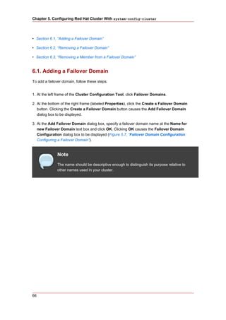
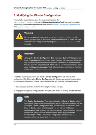
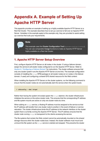
5. Start luci using service luci restart. For example:
# service luci restart
Shutting down luci: [ OK ]
Starting luci: generating https SSL certificates... done
[ OK ]
Please, point your web browser to https://nano-01:8084 to access luci
6. At a Web browser, place the URL of the luci server into the URL address box and click Go
(or the equivalent). The URL syntax for the luci server is
https://luci_server_hostname:8084. The first time you access luci, two SSL certificate
dialog boxes are displayed. Upon acknowledging the dialog boxes, your Web browser
displays the luci login page.
3. Creating A Cluster
Creating a cluster with luci consists of selecting cluster nodes, entering their passwords, and
submitting the request to create a cluster. If the node information and passwords are correct,
Conga automatically installs software into the cluster nodes and starts the cluster. Create a
cluster as follows:
1. As administrator of luci, select the cluster tab.
2. Click Create a New Cluster.
3. At the Cluster Name text box, enter a cluster name. The cluster name cannot exceed 15
characters. Add the node name and password for each cluster node. Enter the node name
for each node in the Node Hostname column; enter the root password for each node in the
in the Root Password column. Check the Enable Shared Storage Support checkbox if
clustered storage is required.
4. Click Submit. Clicking Submit causes the following actions:
a. Cluster software packages to be downloaded onto each cluster node.
b. Cluster software to be installed onto each cluster node.
c. Cluster configuration file to be created and propagated to each node in the cluster.
d. Starting the cluster.
A progress page shows the progress of those actions for each node in the cluster.
When the process of creating a new cluster is complete, a page is displayed providing a
configuration interface for the newly created cluster.
29](https://image.slidesharecdn.com/clusterinlinux-121103082755-phpapp01/85/Cluster-in-linux-39-320.jpg)


![Appendix E. Upgrading A Red Hat
Cluster from RHEL 4 to RHEL 5
This appendix provides a procedure for upgrading a Red Hat cluster from RHEL 4 to RHEL 5.
The procedure includes changes required for Red Hat GFS and CLVM, also. For more
information about Red Hat GFS, refer to Global File System: Configuration and Administration.
For more information about LVM for clusters, refer to LVM Administrator's Guide: Configuration
and Administration.
Upgrading a Red Hat Cluster from RHEL 4 to RHEL 5 consists of stopping the cluster,
converting the configuration from a GULM cluster to a CMAN cluster (only for clusters
configured with the GULM cluster manager/lock manager), adding node IDs, and updating
RHEL and cluster software. To upgrade a Red Hat Cluster from RHEL 4 to RHEL 5, follow
these steps:
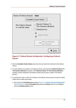
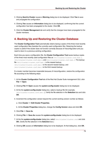
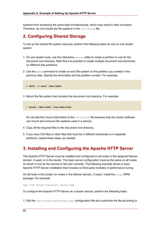
1. Stop client access to cluster high-availability services.
2. At each cluster node, stop the cluster software as follows:
a. Stop all high-availability services.
b. Run service rgmanager stop.
c. Run service gfs stop, if you are using Red Hat GFS.
d. Run service clvmd stop, if CLVM has been used to create clustered volumes.
Note
If clvmd is already stopped, an error message is displayed:
# service clvmd stop
Stopping clvm: [FAILED]
The error message is the expected result when running service clvmd stop
after clvmd has stopped.
e. Depending on the type of cluster manager (either CMAN or GULM), run the following
command or commands:
• CMAN — Run service fenced stop; service cman stop.
• GULM — Run service lock_gulmd stop.
119](https://image.slidesharecdn.com/clusterinlinux-121103082755-phpapp01/85/Cluster-in-linux-129-320.jpg)
![You shouldn't change any of these values if the filesystem is mounted.
Are you sure? [y/n] y
current lock protocol name = "lock_gulm"
new lock protocol name = "lock_dlm"
Done
6. Update the software in the cluster nodes to RHEL 5 and Red Hat Cluster Suite for RHEL 5.
You can acquire and update software through Red Hat Network channels for RHEL 5 and
Red Hat Cluster Suite for RHEL 5.
7. Run lvmconf --enable-cluster.
8. Enable cluster software to start upon reboot. At each node run /sbin/chkconfig as follows:
# chkconfig --level 2345 rgmanager on
# chkconfig --level 2345 gfs on
# chkconfig --level 2345 clvmd on
# chkconfig --level 2345 cman on
9. Reboot the nodes. The RHEL 5 cluster software should start while the nodes reboot. Upon
verification that the Red Hat cluster is running, the upgrade is complete.
<gulm>
<lockserver name="gulmserver1"/>
<lockserver name="gulmserver2"/>
<lockserver name="gulmserver3"/>
</gulm>
Example E.1. GULM XML Elements and Content
121](https://image.slidesharecdn.com/clusterinlinux-121103082755-phpapp01/85/Cluster-in-linux-131-320.jpg)


This document provides an overview of configuring and managing Red Hat Cluster, including installing the software, setting up hardware, and using tools like Conga and system-config-cluster to configure the relationship between cluster nodes, fencing devices, failover domains, and high availability services and resources. It describes the basic steps and components involved in setting up a Red Hat Cluster, as well as an overview of configuration tools available for installing, configuring, and managing Red Hat clusters.